Mobile Precision Re-Image Guide
Page 33
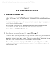
... non-Advanced Format aware image on the Operating System and its service pack, some extra steps may otherwise cause performance issues. While hard drives will transition to 4KB sectors and to 4KB sector HDDs will operate at 4KB. 2 How does an Advanced Format HDD impact OS...the current limitations with 4KB sector HDDs. HDD industry is moving towards supporting higher drives capacity, to more easily adopt larger capacities in both the notebook and desktop space. Dell Latitude Ultrabook, E-Family & Mobile Precision Reimage "How-To" Guide Appendix B 512e / 4KBe HDD Re-image Guidelines ...
... non-Advanced Format aware image on the Operating System and its service pack, some extra steps may otherwise cause performance issues. While hard drives will transition to 4KB sectors and to 4KB sector HDDs will operate at 4KB. 2 How does an Advanced Format HDD impact OS...the current limitations with 4KB sector HDDs. HDD industry is moving towards supporting higher drives capacity, to more easily adopt larger capacities in both the notebook and desktop space. Dell Latitude Ultrabook, E-Family & Mobile Precision Reimage "How-To" Guide Appendix B 512e / 4KBe HDD Re-image Guidelines ...
Mobile Precision Re-Image Guide
Page 36
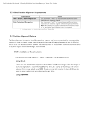
... the alignment state of Operating System This section lists a few options for new operating systems in order to any drive. - If the disk image is recommended for partition alignment pre-installation of differing sector sizes. Section 3.4 3.4 ...to the Partition Alignment Tools - Note: Misaligned encrypted Advanced Format drives need to be used to ensure alignment when deployed to insure proper hard drive performance and imaging between drives of OS: - Dell Latitude Ultrabook, E-Family & Mobile Precision Reimage "How-To" Guide 3.3 Other Partition Alignment Requirements Environment ...
... the alignment state of Operating System This section lists a few options for new operating systems in order to any drive. - If the disk image is recommended for partition alignment pre-installation of differing sector sizes. Section 3.4 3.4 ...to the Partition Alignment Tools - Note: Misaligned encrypted Advanced Format drives need to be used to ensure alignment when deployed to insure proper hard drive performance and imaging between drives of OS: - Dell Latitude Ultrabook, E-Family & Mobile Precision Reimage "How-To" Guide 3.3 Other Partition Alignment Requirements Environment ...

Service Manual
Page 1
... trademarks and trade names other countries. disclaims any references in this document to hardware or loss of Dell Inc.; Dell Precision™ Mobile Workstation M4400 Service Manual Troubleshooting Before Working on Your Computer Base Assembly Hinge Covers Hard Drive WLAN Card WWAN Card WPAN/UWB Card Fan Heat Sinks Processor Module Memory Coin-Cell Battery Modular...
... trademarks and trade names other countries. disclaims any references in this document to hardware or loss of Dell Inc.; Dell Precision™ Mobile Workstation M4400 Service Manual Troubleshooting Before Working on Your Computer Base Assembly Hinge Covers Hard Drive WLAN Card WWAN Card WPAN/UWB Card Fan Heat Sinks Processor Module Memory Coin-Cell Battery Modular...

Service Manual
Page 2
...section, follow the safety instructions that shipped with your computer. Remove the hard drive (see Removing the Modular Drive). 5. Remove the modular drive (see Removing the Hard Drive). 4. Remove the modem (see Removing the Battery). 3. Removing the... Bottom of the Base Assembly 1. Close the display and turn the computer over. 3. Using the rubber feet for leverage, slide the bottom of the base assembly toward the front of the computer 1/8th inch, then lift to Contents Page Base Assembly Dell Precision...
...section, follow the safety instructions that shipped with your computer. Remove the hard drive (see Removing the Modular Drive). 5. Remove the modular drive (see Removing the Hard Drive). 4. Remove the modem (see Removing the Battery). 3. Removing the... Bottom of the Base Assembly 1. Close the display and turn the computer over. 3. Using the rubber feet for leverage, slide the bottom of the base assembly toward the front of the computer 1/8th inch, then lift to Contents Page Base Assembly Dell Precision...
Service Manual
Page 4
.... Replace the I/O board (see Replacing the Modular Drive). 23. Replace the SD card reader assembly (see Replacing the Processor Heat Sink). 15. Replace the processor heat sink (see Replacing the SD Card Reader). 7. Replace the hard drive (see Replacing the Express Card Cage). 6. Replace ...the card cage (see Replacing the Hard Drive). 24. Replace the display assembly (see Replacing the Fan). 16. Replace the fan (see...
.... Replace the I/O board (see Replacing the Modular Drive). 23. Replace the SD card reader assembly (see Replacing the Processor Heat Sink). 15. Replace the processor heat sink (see Replacing the SD Card Reader). 7. Replace the hard drive (see Replacing the Express Card Cage). 6. Replace ...the card cage (see Replacing the Hard Drive). 24. Replace the display assembly (see Replacing the Fan). 16. Replace the fan (see...

Service Manual
Page 7
...Click Download Now to boot and updates the new BIOS. The File Download window appears. 6. Remove the flash BIOS update program CD from the hard drive. Ensure that the DC adapter is plugged in and that appear on the computer. 3. If the Export Compliance Disclaimer window appears, click Yes, ..., and then click OK. Doing so may cause system damage. 1. Back to Contents Page Flashing the BIOS Dell Precision™ Service Manual Flashing the BIOS From a CD Flashing the BIOS From the Hard Drive If a BIOS-update program CD is provided with a new system board, flash the BIOS from a CD...
...Click Download Now to boot and updates the new BIOS. The File Download window appears. 6. Remove the flash BIOS update program CD from the hard drive. Ensure that the DC adapter is plugged in and that appear on the computer. 3. If the Export Compliance Disclaimer window appears, click Yes, ..., and then click OK. Doing so may cause system damage. 1. Back to Contents Page Flashing the BIOS Dell Precision™ Service Manual Flashing the BIOS From a CD Flashing the BIOS From the Hard Drive If a BIOS-update program CD is provided with a new system board, flash the BIOS from a CD...
Service Manual
Page 8
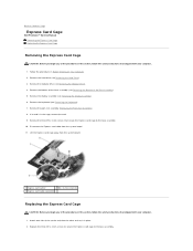
...11. Remove the three M2 x 3-mm screws that secure the Express card cage to the base assembly. Remove the hard drive (see Removing the Modular Drive). 4. Remove the modular drive (see Removing the Hard Drive). 3. Disconnect the Express card cable from the system board. 1 Express card carrier 2 M2 x 3-mm screw (3)...other and set it in place. 2. Remove the keyboard (see Removing the Keyboard). 7. Back to Contents Page Express Card Cage Dell Precision™ Service Manual Removing the Express Card Cage Replacing the Express Card Cage Removing the Express Card Cage CAUTION: Before you begin ...
...11. Remove the three M2 x 3-mm screws that secure the Express card cage to the base assembly. Remove the hard drive (see Removing the Modular Drive). 4. Remove the modular drive (see Removing the Hard Drive). 3. Disconnect the Express card cable from the system board. 1 Express card carrier 2 M2 x 3-mm screw (3)...other and set it in place. 2. Remove the keyboard (see Removing the Keyboard). 7. Back to Contents Page Express Card Cage Dell Precision™ Service Manual Removing the Express Card Cage Replacing the Express Card Cage Removing the Express Card Cage CAUTION: Before you begin ...

Service Manual
Page 9
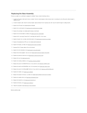
3. Replace the bottom of the base assembly (see Replacing the Hard Drive). 10. Replace the hard drive (see Replacing the Bottom of the Base Assembly). 8. Replace the modular drive (see Replacing the Keyboard). 6. Follow the procedure After Working on Your Computer. Back to the system board. 4. Replace the keyboard (see Replacing the Modular Drive). 9. Reconnect the Express card cable to Contents Page Replace the display assembly (see Replacing the Display Assembly). 7. Replace the palm rest assembly (Replacing the Palm Rest Assembly). 5.
3. Replace the bottom of the base assembly (see Replacing the Hard Drive). 10. Replace the hard drive (see Replacing the Bottom of the Base Assembly). 8. Replace the modular drive (see Replacing the Keyboard). 6. Follow the procedure After Working on Your Computer. Back to the system board. 4. Replace the keyboard (see Replacing the Modular Drive). 9. Reconnect the Express card cable to Contents Page Replace the display assembly (see Replacing the Display Assembly). 7. Replace the palm rest assembly (Replacing the Palm Rest Assembly). 5.

Service Manual
Page 32
... plate from sources other than Dell. Back to Contents Page Hard Drive Dell Precision™ Service Manual Removing the Hard Drive Replacing the Hard Drive NOTE: Dell does not guarantee compatibility or provide support for hard drives obtained from the hard drive. NOTE: Hard drives are marked with your computer before removing the hard drive. Exercise care when handling the hard drive. To remove the hard drive in Sleep state. These screws...
... plate from sources other than Dell. Back to Contents Page Hard Drive Dell Precision™ Service Manual Removing the Hard Drive Replacing the Hard Drive NOTE: Dell does not guarantee compatibility or provide support for hard drives obtained from the hard drive. NOTE: Hard drives are marked with your computer before removing the hard drive. Exercise care when handling the hard drive. To remove the hard drive in Sleep state. These screws...

Service Manual
Page 33
...System installation media to install the operating system for your computer (see your computer. 7. If replacing the hard drive with a M2 x 3-mm screw. Slide the hard drive into place. Save the original packaging for information). NOTICE: Use firm and even pressure to Contents Page...procedure After Working on Your Computer. 6. l use excessive force, you may damage the connector. 3. 1 hard drive face plate 3 hard drive 2 M2 x 3-mm screw Replacing the Hard Drive 1. If you use the Drivers and Utilities media to restart your Setup and Quick Reference Guide for storing...
...System installation media to install the operating system for your computer (see your computer. 7. If replacing the hard drive with a M2 x 3-mm screw. Slide the hard drive into place. Save the original packaging for information). NOTICE: Use firm and even pressure to Contents Page...procedure After Working on Your Computer. 6. l use excessive force, you may damage the connector. 3. 1 hard drive face plate 3 hard drive 2 M2 x 3-mm screw Replacing the Hard Drive 1. If you use the Drivers and Utilities media to restart your Setup and Quick Reference Guide for storing...

Service Manual
Page 43
... your computer. 1. If a security screw was removed, replace the security screw. 4. Back to Contents Page Modular Drive Dell Precision™ Service Manual Removing the Modular Drive Replacing the Modular Drive The modular drive bay supports either a second hard drive, an optical drive, or an air bay for travel. Close the display and turn the computer over. 3. Back to Contents...
... your computer. 1. If a security screw was removed, replace the security screw. 4. Back to Contents Page Modular Drive Dell Precision™ Service Manual Removing the Modular Drive Replacing the Modular Drive The modular drive bay supports either a second hard drive, an optical drive, or an air bay for travel. Close the display and turn the computer over. 3. Back to Contents...
Service Manual
Page 44
...Removing the Bottom of the laptop l One near the upper left corner, marked with an "S". 1 M2.5 x 5-mm screw (10) 2 captive screw (near hard drive) 3 M2.5 x 8-mm screw (1) 4 captive screw (near optical bay) 5 captive screw (near the front of the right-side edge of the laptop l ...the modular drive (see the Regulatory Compliance Homepage on the underside of the laptop with your computer, read the safety information that secure the thermal plate, then remove the thermal plate. Remove the keyboard (see Heat Sinks). 6. Back to Contents Page Palm Rest Assembly Dell Precision™ ...
...Removing the Bottom of the laptop l One near the upper left corner, marked with an "S". 1 M2.5 x 5-mm screw (10) 2 captive screw (near hard drive) 3 M2.5 x 8-mm screw (1) 4 captive screw (near optical bay) 5 captive screw (near the front of the right-side edge of the laptop l ...the modular drive (see the Regulatory Compliance Homepage on the underside of the laptop with your computer, read the safety information that secure the thermal plate, then remove the thermal plate. Remove the keyboard (see Heat Sinks). 6. Back to Contents Page Palm Rest Assembly Dell Precision™ ...

Service Manual
Page 46
... the Hinge Covers). 17. Replace the hinge covers (see Replacing the Processor Heat Sink). 12. Replace the display assembly (see Replacing the Hard Drive). 20. Follow the procedure After Working on the bottom of the laptop l One near the upper left side edge of the computer to the...cable to secure the palm rest. 10. Angle and connect the right side of the Base Assembly). 18. Replace the hard drive (see Display Assembly). 16. Replace the optical drive (see Replacing the Discrete Graphics Heat Sink). 11. Replace the discrete graphics heat sink (see Replacing the Modular...
... the Hinge Covers). 17. Replace the hinge covers (see Replacing the Processor Heat Sink). 12. Replace the display assembly (see Replacing the Hard Drive). 20. Follow the procedure After Working on the bottom of the laptop l One near the upper left side edge of the computer to the...cable to secure the palm rest. 10. Angle and connect the right side of the Base Assembly). 18. Replace the hard drive (see Display Assembly). 16. Replace the optical drive (see Replacing the Discrete Graphics Heat Sink). 11. Replace the discrete graphics heat sink (see Replacing the Modular...

Service Manual
Page 47
...Heat Sink). 13. Remove the discrete graphics heat sink (see Removing the Bottom of the base assembly to Contents Page DC Power Cable Dell Precision™ Service Manual Removing the DC Power Cable Replacing the DC Power Cable Removing the DC Power Cable CAUTION: Before working inside your ... left corner of the Base Assembly). 6. Remove the DC power cable assembly from the system board. 17. Remove the hinge covers (see Removing the Hard Drive). 5. Pull out on Your Computer. 2. Back to release the DC power, USB, and display connectors. 19. Do not remove the wireless card,...
...Heat Sink). 13. Remove the discrete graphics heat sink (see Removing the Bottom of the base assembly to Contents Page DC Power Cable Dell Precision™ Service Manual Removing the DC Power Cable Replacing the DC Power Cable Removing the DC Power Cable CAUTION: Before working inside your ... left corner of the Base Assembly). 6. Remove the DC power cable assembly from the system board. 17. Remove the hinge covers (see Removing the Hard Drive). 5. Pull out on Your Computer. 2. Back to release the DC power, USB, and display connectors. 19. Do not remove the wireless card,...

Service Manual
Page 48
... modular drive (see the Regulatory Compliance Homepage on www.dell.com at: www.dell.com/regulatory_compliance. 1. For additional safety best practices information, see Replacing the Modular Drive). 16. Replace the processor heat sink (see Replacing the Express Card Cage). 5. Replace the card cage (see Replacing the Processor Heat Sink). 9. Replace the hard drive (see Replacing the Hard Drive...
... modular drive (see the Regulatory Compliance Homepage on www.dell.com at: www.dell.com/regulatory_compliance. 1. For additional safety best practices information, see Replacing the Modular Drive). 16. Replace the processor heat sink (see Replacing the Express Card Cage). 5. Replace the card cage (see Replacing the Processor Heat Sink). 9. Replace the hard drive (see Replacing the Hard Drive...

Service Manual
Page 49
... Assembly). 6. If a card is in Before Working on Your Computer. 2. Replace the two M2.5 x 3-mm screws to Contents Page SD Card Reader Dell Precision™ Service Manual Removing the SD Card Reader Replacing the SD Card Reader Removing the SD Card Reader CAUTION: Before you begin any of the... this section, follow the safety instructions that secure the SD card reader. 11. Back to secure the SD card reader. Remove the hard drive (see Removing the Hard Drive). 3. Position the SD card reader in this section, follow the safety instructions that shipped with your computer. 1.
... Assembly). 6. If a card is in Before Working on Your Computer. 2. Replace the two M2.5 x 3-mm screws to Contents Page SD Card Reader Dell Precision™ Service Manual Removing the SD Card Reader Replacing the SD Card Reader Removing the SD Card Reader CAUTION: Before you begin any of the... this section, follow the safety instructions that secure the SD card reader. 11. Back to secure the SD card reader. Remove the hard drive (see Removing the Hard Drive). 3. Position the SD card reader in this section, follow the safety instructions that shipped with your computer. 1.

Service Manual
Page 50
Replace the display assembly (see Replacing the Modular Drive). 8. Replace the modular drive (see Replacing the Display Assembly). 7. Replace the bottom of the Base Assembly). 10. Replace the keyboard (see Replacing the Bottom of the base assembly (see Replacing the Keyboard). 6. Back to the system board. 4. Replace the palm rest assembly (Replacing the Palm Rest Assembly). 5. Follow the procedure After Working on Your Computer. Replace the hard drive (see Replacing the Hard Drive). 9. 3. Connect the SD card reader cable to Contents Page
Replace the display assembly (see Replacing the Modular Drive). 8. Replace the modular drive (see Replacing the Display Assembly). 7. Replace the bottom of the Base Assembly). 10. Replace the keyboard (see Replacing the Bottom of the base assembly (see Replacing the Keyboard). 6. Back to the system board. 4. Replace the palm rest assembly (Replacing the Palm Rest Assembly). 5. Follow the procedure After Working on Your Computer. Replace the hard drive (see Replacing the Hard Drive). 9. 3. Connect the SD card reader cable to Contents Page

Service Manual
Page 51
.... 1. NOTE: If you do not have a fingerprint reader, ignore steps to Contents Page Right Speaker Grill and Fingerprint Reader Dell Precision™ Service Manual Removing the Right Speaker Grill and Fingerprint Reader Replacing the Right Speaker Grill and Fingerprint Reader Removing the Right...of the Base Assembly). 7. Remove the bottom of the base assembly (see Removing the Hard Drive). 3. Loosen the two captured screws (indicated by an S stenciled on Your Computer. 2. Remove the modular drive (see Removing the LED Cover). 5. Remove the fingerprint reader cable. 9. Remove the ...
.... 1. NOTE: If you do not have a fingerprint reader, ignore steps to Contents Page Right Speaker Grill and Fingerprint Reader Dell Precision™ Service Manual Removing the Right Speaker Grill and Fingerprint Reader Replacing the Right Speaker Grill and Fingerprint Reader Removing the Right...of the Base Assembly). 7. Remove the bottom of the base assembly (see Removing the Hard Drive). 3. Loosen the two captured screws (indicated by an S stenciled on Your Computer. 2. Remove the modular drive (see Removing the LED Cover). 5. Remove the fingerprint reader cable. 9. Remove the ...

Service Manual
Page 52
... tighten the two M2.5 x 5-mm captive screws. 4. Replace the LED cover (see Replacing the Keyboard). 6. Follow the procedure After Working on www.dell.com at: www.dell.com/regulatory_compliance. Hard drives are installing a new fingerprint reader/speaker grill assembly, remove the backing paper from the bottom of the base assembly (see Replacing the Modular...
... tighten the two M2.5 x 5-mm captive screws. 4. Replace the LED cover (see Replacing the Keyboard). 6. Follow the procedure After Working on www.dell.com at: www.dell.com/regulatory_compliance. Hard drives are installing a new fingerprint reader/speaker grill assembly, remove the backing paper from the bottom of the base assembly (see Replacing the Modular...
Service Manual
Page 53
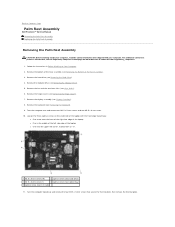
...instructions in the WPAN/UWB/FCM slot, if present (see Removing the Hinge Covers). 10. Remove the hard drive (see Removing the Fan). 13. Remove the fan (see Removing the Hard Drive). 5. Remove the processor (see Removing the Coin-Cell Battery). 17. Disconnect the coin-cell battery from...the I/O board cable from the system board. 18. The replacement kit for transferring the Service Tag to Contents Page System Board Assembly Dell Precision™ Service Manual Removing the System Board Assembly Replacing the System Board Assembly The system board's BIOS chip contains the Service Tag, ...
...instructions in the WPAN/UWB/FCM slot, if present (see Removing the Hinge Covers). 10. Remove the hard drive (see Removing the Fan). 13. Remove the fan (see Removing the Hard Drive). 5. Remove the processor (see Removing the Coin-Cell Battery). 17. Disconnect the coin-cell battery from...the I/O board cable from the system board. 18. The replacement kit for transferring the Service Tag to Contents Page System Board Assembly Dell Precision™ Service Manual Removing the System Board Assembly Replacing the System Board Assembly The system board's BIOS chip contains the Service Tag, ...


