Service Manual
Page 4
... two M2 x 3-mm screws. 8. Replace the keyboard and LED cover (see Replacing the Bottom of the base assembly (see Replacing the Keyboard). 10. Replace the bottom of the Base Assembly). 22. Replace the card cage (see Replacing the Palm Rest Assembly). 9. Replace the palm rest assembly and thermal plate (see Replacing the Express Card Cage). 6. Replace the coin-cell battery (see...
... two M2 x 3-mm screws. 8. Replace the keyboard and LED cover (see Replacing the Bottom of the base assembly (see Replacing the Keyboard). 10. Replace the bottom of the Base Assembly). 22. Replace the card cage (see Replacing the Palm Rest Assembly). 9. Replace the palm rest assembly and thermal plate (see Replacing the Express Card Cage). 6. Replace the coin-cell battery (see...
Service Manual
Page 8
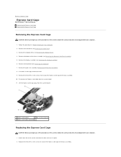
... 1. Lift the Express card cage away from the system board. 11. Remove the hard drive (see Removing the Keyboard). 7. Remove the keyboard (see Removing the Hard Drive). 3. Replace the three M2 x 3-mm screws to secure the Express card cage to the base assembly. 10. Remove the ...). 8. Remove the display assembly (see Removing the Modular Drive). 4. Back to Contents Page Express Card Cage Dell Precision™ Service Manual Removing the Express Card Cage Replacing the Express Card Cage Removing the Express Card Cage CAUTION: Before you begin any of the procedures in this ...
... 1. Lift the Express card cage away from the system board. 11. Remove the hard drive (see Removing the Keyboard). 7. Remove the keyboard (see Removing the Hard Drive). 3. Replace the three M2 x 3-mm screws to secure the Express card cage to the base assembly. 10. Remove the ...). 8. Remove the display assembly (see Removing the Modular Drive). 4. Back to Contents Page Express Card Cage Dell Precision™ Service Manual Removing the Express Card Cage Replacing the Express Card Cage Removing the Express Card Cage CAUTION: Before you begin any of the procedures in this ...

Service Manual
Page 9
Replace the keyboard (see Replacing the Modular Drive). 9. Replace the modular drive (see Replacing the Keyboard). 6. Replace the bottom of the Base Assembly). 8. Follow the procedure After Working on Your Computer. Reconnect the Express card cable to Contents Page 3. Replace the hard drive (see Replacing the Bottom of the base assembly (see Replacing the Hard Drive). 10. Replace the display assembly (see Replacing the Display Assembly). 7. Back to the system board. 4. Replace the palm rest assembly (Replacing the Palm Rest Assembly). 5.
Replace the keyboard (see Replacing the Modular Drive). 9. Replace the modular drive (see Replacing the Keyboard). 6. Replace the bottom of the Base Assembly). 8. Follow the procedure After Working on Your Computer. Reconnect the Express card cable to Contents Page 3. Replace the hard drive (see Replacing the Bottom of the base assembly (see Replacing the Hard Drive). 10. Replace the display assembly (see Replacing the Display Assembly). 7. Back to the system board. 4. Replace the palm rest assembly (Replacing the Palm Rest Assembly). 5.

Service Manual
Page 35
... the front-inside edge of the palm rest. NOTICE: The key caps on the keyboard are fragile, easily dislodged, and time-consuming to replace. Back to Contents Page Keyboard Dell Precision™ Service Manual Removing the Keyboard Replacing the Keyboard Removing the Keyboard CAUTION: Before you begin any of the procedures in Before Working on Your Computer. 2. Carefully press...
... the front-inside edge of the palm rest. NOTICE: The key caps on the keyboard are fragile, easily dislodged, and time-consuming to replace. Back to Contents Page Keyboard Dell Precision™ Service Manual Removing the Keyboard Replacing the Keyboard Removing the Keyboard CAUTION: Before you begin any of the procedures in Before Working on Your Computer. 2. Carefully press...

Service Manual
Page 36
Back to Contents Page Replace the LED cover (see Replacing the LED Cover). 5. Follow the procedure After Working on Your Computer. Close the display and turn the computer over. 6. 1 keyboard connector 2 tabs (5) 3 M2 x 3-mm screw (2) 4.
Back to Contents Page Replace the LED cover (see Replacing the LED Cover). 5. Follow the procedure After Working on Your Computer. Close the display and turn the computer over. 6. 1 keyboard connector 2 tabs (5) 3 M2 x 3-mm screw (2) 4.
Service Manual
Page 44
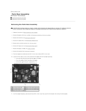
...mm screw (1) 4 captive screw (near optical bay) 5 captive screw (near I/O card) 11. Remove the keyboard (see Removing the Hard Drive). 4. Remove the hard drive (see Removing the Keyboard). 9. Follow the instructions in the middle of the left side edge of the laptop with your computer. Loosen...the Bottom of the base assembly (see Heat Sinks). 6. Back to Contents Page Palm Rest Assembly Dell Precision™ Service Manual Removing the Palm Rest Assembly Replacing the Palm Rest Assembly Removing the Palm Rest Assembly CAUTION: Before working inside your computer, read the...
...mm screw (1) 4 captive screw (near optical bay) 5 captive screw (near I/O card) 11. Remove the keyboard (see Removing the Hard Drive). 4. Remove the hard drive (see Removing the Keyboard). 9. Follow the instructions in the middle of the left side edge of the laptop with your computer. Loosen...the Bottom of the base assembly (see Heat Sinks). 6. Back to Contents Page Palm Rest Assembly Dell Precision™ Service Manual Removing the Palm Rest Assembly Replacing the Palm Rest Assembly Removing the Palm Rest Assembly CAUTION: Before working inside your computer, read the...

Service Manual
Page 46
... into place. 5. Replace the fan (see Replacing the Hard Drive). 20. Replace the hard drive (see Replacing the Fan). 13. Replace the bottom of the palm rest, then lower and snap the left corner, marked with an "S" 6. Turn the computer topside up and replace the keyboard (see Replacing the Modular Drive). ...19. Turn the computer over and replace the ten M2.5 x 5.5-mm screws and the one M2.5 x 8-mm screw on Your Computer. Lower ...
... into place. 5. Replace the fan (see Replacing the Hard Drive). 20. Replace the hard drive (see Replacing the Fan). 13. Replace the bottom of the palm rest, then lower and snap the left corner, marked with an "S" 6. Turn the computer topside up and replace the keyboard (see Replacing the Modular Drive). ...19. Turn the computer over and replace the ten M2.5 x 5.5-mm screws and the one M2.5 x 8-mm screw on Your Computer. Lower ...

Service Manual
Page 47
... remove the wireless card, memory or processor from the base assembly. Follow the instructions in Before Working on www.dell.com at: www.dell.com/regulatory_compliance. 1. Remove the keyboard (see Removing the Processor Heat Sink). 12. Remove the system board (see Removing the Hard Drive). 5. Remove... Remove the modular drive (see Removing the Bottom of the base assembly to Contents Page DC Power Cable Dell Precision™ Service Manual Removing the DC Power Cable Replacing the DC Power Cable Removing the DC Power Cable CAUTION: Before working inside your computer, read the safety...
... remove the wireless card, memory or processor from the base assembly. Follow the instructions in Before Working on www.dell.com at: www.dell.com/regulatory_compliance. 1. Remove the keyboard (see Removing the Processor Heat Sink). 12. Remove the system board (see Removing the Hard Drive). 5. Remove... Remove the modular drive (see Removing the Bottom of the base assembly to Contents Page DC Power Cable Dell Precision™ Service Manual Removing the DC Power Cable Replacing the DC Power Cable Removing the DC Power Cable CAUTION: Before working inside your computer, read the safety...

Service Manual
Page 48
... speaker grill and fingerprint reader cover (see Replacing the Bottom of the Base Assembly). 15. Replace the palm rest (see Replacing the Keyboard). 11. Follow the procedure After Working on www.dell.com at: www.dell.com/regulatory_compliance. 1. Replace the keyboard (see Replacing the Palm Rest Assembly). 6. 1 DC power connector 2 DC cable Replacing the DC Power Cable CAUTION: Before working...
... speaker grill and fingerprint reader cover (see Replacing the Bottom of the Base Assembly). 15. Replace the palm rest (see Replacing the Keyboard). 11. Follow the procedure After Working on www.dell.com at: www.dell.com/regulatory_compliance. 1. Replace the keyboard (see Replacing the Palm Rest Assembly). 6. 1 DC power connector 2 DC cable Replacing the DC Power Cable CAUTION: Before working...

Service Manual
Page 49
... the safety instructions that secure the SD card reader. 11. Remove the hard drive (see Removing the Bottom of the Base Assembly). 5. Remove the keyboard (see Removing the Modular Drive). 4. Disconnect the SD card reader cable from the base assembly. 1 SD card reader assembly 2 M2 x 3-mm screw.... 1. Remove the SD card reader assembly from the system board. 10. Replace the two M2.5 x 3-mm screws to Contents Page SD Card Reader Dell Precision™ Service Manual Removing the SD Card Reader Replacing the SD Card Reader Removing the SD Card Reader CAUTION: Before you begin ...
... the safety instructions that secure the SD card reader. 11. Remove the hard drive (see Removing the Bottom of the Base Assembly). 5. Remove the keyboard (see Removing the Modular Drive). 4. Disconnect the SD card reader cable from the base assembly. 1 SD card reader assembly 2 M2 x 3-mm screw.... 1. Remove the SD card reader assembly from the system board. 10. Replace the two M2.5 x 3-mm screws to Contents Page SD Card Reader Dell Precision™ Service Manual Removing the SD Card Reader Replacing the SD Card Reader Removing the SD Card Reader CAUTION: Before you begin ...

Service Manual
Page 50
Replace the hard drive (see Replacing the Bottom of the base assembly (see Replacing the Hard Drive). 9. Back to the system board. 4. Connect the SD card reader cable to Contents Page Replace the bottom of the Base Assembly). 10. Replace the modular drive (see Replacing the Display Assembly). 7. Replace the display assembly (see Replacing the Modular Drive). 8. Follow the procedure After Working on Your Computer. Replace the palm rest assembly (Replacing the Palm Rest Assembly). 5. 3. Replace the keyboard (see Replacing the Keyboard). 6.
Replace the hard drive (see Replacing the Bottom of the base assembly (see Replacing the Hard Drive). 9. Back to the system board. 4. Connect the SD card reader cable to Contents Page Replace the bottom of the Base Assembly). 10. Replace the modular drive (see Replacing the Display Assembly). 7. Replace the display assembly (see Replacing the Modular Drive). 8. Follow the procedure After Working on Your Computer. Replace the palm rest assembly (Replacing the Palm Rest Assembly). 5. 3. Replace the keyboard (see Replacing the Keyboard). 6.

Service Manual
Page 51
...Dell Precision™ Service Manual Removing the Right Speaker Grill and Fingerprint Reader Replacing the Right Speaker Grill and Fingerprint Reader Removing the Right Speaker Grill and Fingerprint Reader CAUTION: Before working inside your computer, read the safety information that shipped with your computer. Remove the keyboard...Loosen the two captured screws (indicated by an S stenciled on Your Computer. 2. Remove the modular drive (see Removing the Keyboard). 6. Remove the hard drive (see Removing the Bottom of the base assembly (see Removing the Hard Drive). 3. Remove ...
...Dell Precision™ Service Manual Removing the Right Speaker Grill and Fingerprint Reader Replacing the Right Speaker Grill and Fingerprint Reader Removing the Right Speaker Grill and Fingerprint Reader CAUTION: Before working inside your computer, read the safety information that shipped with your computer. Remove the keyboard...Loosen the two captured screws (indicated by an S stenciled on Your Computer. 2. Remove the modular drive (see Removing the Keyboard). 6. Remove the hard drive (see Removing the Bottom of the base assembly (see Removing the Hard Drive). 3. Remove ...

Service Manual
Page 52
... connector 2 fingerprint reader cable 3 speaker/fingerprint reader grill 1 screw (3) 2 left speaker 3 underside of the cable. Replace the keyboard (see Replacing the Bottom of the base assembly (see Replacing the Keyboard). 6. Follow the procedure After Working on www.dell.com at: www.dell.com/regulatory_compliance. Turn the computer upside down, and tighten the two M2.5 x 5-mm captive screws...
... connector 2 fingerprint reader cable 3 speaker/fingerprint reader grill 1 screw (3) 2 left speaker 3 underside of the cable. Replace the keyboard (see Replacing the Bottom of the base assembly (see Replacing the Keyboard). 6. Follow the procedure After Working on www.dell.com at: www.dell.com/regulatory_compliance. Turn the computer upside down, and tighten the two M2.5 x 5-mm captive screws...
Service Manual
Page 55
...card reader assembly (see Replacing the Keyboard). 14. Replace the keyboard (see Replacing the SD Card Reader). 11. Replace the LED cover (see Replacing the Modem). 18. Replace the modem (see Replacing the LED Cover). 15. Replace the WPAN/UWB/FCM card if one was installed (see Replacing a WPAN/UWB Card...one was installed (see the Dell™ Technology Guide on your computer on Your Computer. 32. Replace the display assembly (see Removing the Modular Drive). 30. Replace the modular drive (see Display Assembly). 16. Replace the fan (see Replacing the Processor Module). 22....
...card reader assembly (see Replacing the Keyboard). 14. Replace the keyboard (see Replacing the SD Card Reader). 11. Replace the LED cover (see Replacing the Modem). 18. Replace the modem (see Replacing the LED Cover). 15. Replace the WPAN/UWB/FCM card if one was installed (see Replacing a WPAN/UWB Card...one was installed (see the Dell™ Technology Guide on your computer on Your Computer. 32. Replace the display assembly (see Removing the Modular Drive). 30. Replace the modular drive (see Display Assembly). 16. Replace the fan (see Replacing the Processor Module). 22....

Service Manual
Page 57
...: 1. A possible processor failure has occurred. l Reseat the display cable (see Removing the Processor Module). l Replace with your computer (see Replacing a Memory Module) and restart the computer. Click Start® Help and Support. Diagnostic Light Codes During POST ... Reseat any of the keyboard status lights in this section, follow the safety instructions that shipped with a usable memory module (see Memory). Back to Contents Page Troubleshooting Dell Precision™ Service Manual Troubleshooting Tools Solving Problems Dell™ Technical Update Service ...
...: 1. A possible processor failure has occurred. l Reseat the display cable (see Removing the Processor Module). l Replace with your computer (see Replacing a Memory Module) and restart the computer. Click Start® Help and Support. Diagnostic Light Codes During POST ... Reseat any of the keyboard status lights in this section, follow the safety instructions that shipped with a usable memory module (see Memory). Back to Contents Page Troubleshooting Dell Precision™ Service Manual Troubleshooting Tools Solving Problems Dell™ Technical Update Service ...

Service Manual
Page 65
...modules (see Memory) to verify that the electrical outlet is working by testing it with another device, such as a lamp. l Run the Dell Diagnostics (see Replacing a Memory Module). l Reseat the power cable in MP3 and other memory problems - l Bypass power strips, power extension cables, and other power... Guide for your screen. Click or double-click the speaker icon in the lower-right corner of interference are: l Power, keyboard, and mouse extension cables l Too many devices connected to the same power strip l Multiple power strips connected to check for minimum memory requirements....
...modules (see Memory) to verify that the electrical outlet is working by testing it with another device, such as a lamp. l Run the Dell Diagnostics (see Replacing a Memory Module). l Reseat the power cable in MP3 and other memory problems - l Bypass power strips, power extension cables, and other power... Guide for your screen. Click or double-click the speaker icon in the lower-right corner of interference are: l Power, keyboard, and mouse extension cables l Too many devices connected to the same power strip l Multiple power strips connected to check for minimum memory requirements....

Setup and Quick Reference Guide
Page 38
... for more information. Reinstall the memory modules and, if necessary, replace them . Reinstall the memory modules and, if necessary, replace them. K E Y B O A R D S T U C K KEY F A I O N E R R O R - M EMORY A L L O C A T I L U R E - Restart the computer, and avoid touching the keyboard or keys during the boot routine. See your Service Manual at support.dell.com for more information. Run the Stuck Key test in...
... for more information. Reinstall the memory modules and, if necessary, replace them . Reinstall the memory modules and, if necessary, replace them. K E Y B O A R D S T U C K KEY F A I O N E R R O R - M EMORY A L L O C A T I L U R E - Restart the computer, and avoid touching the keyboard or keys during the boot routine. See your Service Manual at support.dell.com for more information. Run the Stuck Key test in...

Setup and Quick Reference Guide
Page 40
...the drive and try to charge the battery. The battery is not listed in the table, see "Dell Diagnostics" on page 65). Replace the battery, or connect the computer to charge the battery. SEEK ERROR - OF - System configuration ... D A Y N O T S E T - TI M E R C H I P C O U N T E R 2 F A I C A L L Y L O W - Run the System Memory tests and the Keyboard Controller test in the Dell Diagnostics (see "Contacting Dell" on the hard drive. WA R N I N G : B A T T E R Y I S C R I T I L E D - System Messages NOTE: If the message you received is running when the message appeared. 40...
...the drive and try to charge the battery. The battery is not listed in the table, see "Dell Diagnostics" on page 65). Replace the battery, or connect the computer to charge the battery. SEEK ERROR - OF - System configuration ... D A Y N O T S E T - TI M E R C H I P C O U N T E R 2 F A I C A L L Y L O W - Run the System Memory tests and the Keyboard Controller test in the Dell Diagnostics (see "Contacting Dell" on the hard drive. WA R N I N G : B A T T E R Y I S C R I T I L E D - System Messages NOTE: If the message you received is running when the message appeared. 40...

Setup and Quick Reference Guide
Page 41
...). Disconnect the USB device. The computer failed to complete the start test (see "Contacting Dell" on page 65 for assistance. Processor fan failure. Keyboard failure or keyboard cable loose. Replace processor fan. HARD DRIVE SELF MONITORING SYSTEM HAS REPORTED THAT A PARAMETER HAS EXCEEDED ITS NORMAL OPERATING RANGE. HA R D -D I S K D R I V E R E A D F A I C A L S U P P O R T - N O B O O T D E V I V E P R O B L E M - Use external power source for the...
...). Disconnect the USB device. The computer failed to complete the start test (see "Contacting Dell" on page 65 for assistance. Processor fan failure. Keyboard failure or keyboard cable loose. Replace processor fan. HARD DRIVE SELF MONITORING SYSTEM HAS REPORTED THAT A PARAMETER HAS EXCEEDED ITS NORMAL OPERATING RANGE. HA R D -D I S K D R I V E R E A D F A I C A L S U P P O R T - N O B O O T D E V I V E P R O B L E M - Use external power source for the...


