Mobile Precision Re-Image Guide
Page 9
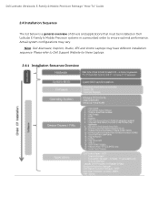
Actual system configurations may have different installation sequence. Please refer to ensure optimal performance. Dell Latitude Ultrabook, E-Family & Mobile Precision Reimage "How-To" Guide 2.4 Installation Sequence The list below is a general overview of drivers and applications that must be installed on Dell Latitude E-Family & Mobile Precision systems in a prescribed order to Dell Support Website for these Laptops. 2.4.1 Installation Sequence Overview Note: Dell Alienware, Inspiron, Studio, XPS and Vostro Laptops may vary.
Actual system configurations may have different installation sequence. Please refer to ensure optimal performance. Dell Latitude Ultrabook, E-Family & Mobile Precision Reimage "How-To" Guide 2.4 Installation Sequence The list below is a general overview of drivers and applications that must be installed on Dell Latitude E-Family & Mobile Precision systems in a prescribed order to Dell Support Website for these Laptops. 2.4.1 Installation Sequence Overview Note: Dell Alienware, Inspiron, Studio, XPS and Vostro Laptops may vary.
Mobile Precision Re-Image Guide
Page 23
... into your laptop to Table B3 under Appendix-B for WiMAX controllers featured in Dell E-Family systems. To obtain WiMAX functionality, install the WiMAX software applicable to uninstall Dell Control Point Connection manager or uncheck the Wi-Fi control within Dell Control Point Connection Manager Because it's based on 4th generations Latitude E-Family & Precision Mobile. ...
... into your laptop to Table B3 under Appendix-B for WiMAX controllers featured in Dell E-Family systems. To obtain WiMAX functionality, install the WiMAX software applicable to uninstall Dell Control Point Connection manager or uncheck the Wi-Fi control within Dell Control Point Connection Manager Because it's based on 4th generations Latitude E-Family & Precision Mobile. ...

Service Manual
Page 18
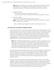
... Assembly). 4. Close the display and turn the computer over. 3. NOTICE: Position all cables to Contents Page Display Assembly Dell Precision™ Service Manual Removing the Display Assembly Replacing the Display Assembly Removing the Display Bezel Replacing the Display Bezel Removing the .... 6. Remove the two M2.5 x 5-mm screws from the laptop. 1 display cable 2 WPAN antenna cable 3 WLAN antenna cable 4 WWAN antenna cable 7. Follow the instructions in Before Working on www.dell.com at: www.dell.com/regulatory_compliance. Remove the bottom of the base assembly (see Removing...
... Assembly). 4. Close the display and turn the computer over. 3. NOTICE: Position all cables to Contents Page Display Assembly Dell Precision™ Service Manual Removing the Display Assembly Replacing the Display Assembly Removing the Display Bezel Replacing the Display Bezel Removing the .... 6. Remove the two M2.5 x 5-mm screws from the laptop. 1 display cable 2 WPAN antenna cable 3 WLAN antenna cable 4 WWAN antenna cable 7. Follow the instructions in Before Working on www.dell.com at: www.dell.com/regulatory_compliance. Remove the bottom of the base assembly (see Removing...
Service Manual
Page 20
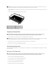
...is required for the corners, especially for the bezels used with the small rectangular opening on the display bezel. Removing the Display Panel The Dell Precision M4400 laptop includes either a CCFL display panel or an LED display panel. To release the snaps along the top and bottom of the bezel, push... read the safety information that shipped with your fingers to gently snap the bezel into place to secure it to the configuration of the laptop you are released, lift the bezel from the LCD, while pushing down . Remove the display assembly (see Replacing the Display Assembly). Starting ...
...is required for the corners, especially for the bezels used with the small rectangular opening on the display bezel. Removing the Display Panel The Dell Precision M4400 laptop includes either a CCFL display panel or an LED display panel. To release the snaps along the top and bottom of the bezel, push... read the safety information that shipped with your fingers to gently snap the bezel into place to secure it to the configuration of the laptop you are released, lift the bezel from the LCD, while pushing down . Remove the display assembly (see Replacing the Display Assembly). Starting ...

Service Manual
Page 22
... using the pull tab. 1 back of the display panel. Connect the backlight cable to the display. 6. Replacing the Display Panel The Dell Precision M4400 laptop includes either a CCFL display panel or an LED display panel. NOTE: The display panel brackets are assembling. Connect the display cable to ...workspace, in front of the display panel. 3. Use the alignment posts in the display cover. Lift the display panel out of the laptop you are labeled L (left display panel brackets, then remove the brackets. Position the display panel in the display cover to the configuration...
... using the pull tab. 1 back of the display panel. Connect the backlight cable to the display. 6. Replacing the Display Panel The Dell Precision M4400 laptop includes either a CCFL display panel or an LED display panel. NOTE: The display panel brackets are assembling. Connect the display cable to ...workspace, in front of the display panel. 3. Use the alignment posts in the display cover. Lift the display panel out of the laptop you are labeled L (left display panel brackets, then remove the brackets. Position the display panel in the display cover to the configuration...

Service Manual
Page 32
... of the base assembly is on or in Before Working on the bottom of the hard drive if you remove the hard drive from the laptop, the four screws securing the hard drive are extremely fragile. NOTICE: To prevent data loss, turn off your computer. NOTICE: When the...: 1. Remove the face plate screw and then the face plate from sources other than Dell. Back to Contents Page Hard Drive Dell Precision™ Service Manual Removing the Hard Drive Replacing the Hard Drive NOTE: Dell does not guarantee compatibility or provide support for hard drives obtained from the hard drive....
... of the base assembly is on or in Before Working on the bottom of the hard drive if you remove the hard drive from the laptop, the four screws securing the hard drive are extremely fragile. NOTICE: To prevent data loss, turn off your computer. NOTICE: When the...: 1. Remove the face plate screw and then the face plate from sources other than Dell. Back to Contents Page Hard Drive Dell Precision™ Service Manual Removing the Hard Drive Replacing the Hard Drive NOTE: Dell does not guarantee compatibility or provide support for hard drives obtained from the hard drive....

Service Manual
Page 37
... to remove it from the laptop. 1 LED cover 2 scribe Replacing the LED Cover CAUTION: Before you begin any of the LED cover. Follow the procedures in Before Working on Your Computer. Follow the procedure After Working on Your Computer. 2. Back to Contents Page LED Cover Dell Precision™ Service Manual Removing the LED...
... to remove it from the laptop. 1 LED cover 2 scribe Replacing the LED Cover CAUTION: Before you begin any of the LED cover. Follow the procedures in Before Working on Your Computer. Follow the procedure After Working on Your Computer. 2. Back to Contents Page LED Cover Dell Precision™ Service Manual Removing the LED...
Service Manual
Page 44
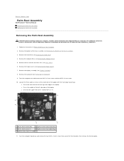
... Assembly Dell Precision™ Service Manual Removing the Palm Rest Assembly Replacing the Palm Rest Assembly Removing the Palm Rest Assembly CAUTION: Before working inside your computer. Remove the fan and the two heat sinks (see the Regulatory Compliance Homepage on www.dell.com at: www.dell.com/... the computer over and remove ten M2.5 x 5-mm screws and one M2.5 x 8-mm screw. 10. Remove the modular drive (see Removing the Bottom of the laptop l One near the upper left corner, marked with an "S". 1 M2.5 x 5-mm screw (10) 2 captive screw (near hard drive) 3 M2.5 x 8-mm ...
... Assembly Dell Precision™ Service Manual Removing the Palm Rest Assembly Replacing the Palm Rest Assembly Removing the Palm Rest Assembly CAUTION: Before working inside your computer. Remove the fan and the two heat sinks (see the Regulatory Compliance Homepage on www.dell.com at: www.dell.com/... the computer over and remove ten M2.5 x 5-mm screws and one M2.5 x 8-mm screw. 10. Remove the modular drive (see Removing the Bottom of the laptop l One near the upper left corner, marked with an "S". 1 M2.5 x 5-mm screw (10) 2 captive screw (near hard drive) 3 M2.5 x 8-mm ...

Service Manual
Page 46
... Replacing the Hinge Covers). 17. Replace the hard drive (see Replacing the Modular Drive). 19. Follow the procedure After Working on the bottom of the laptop l One near the upper left side edge of the computer to secure it. 8. Replace the optical drive (see Replacing the Hard Drive). 20. Back ... upside down with the front edge toward you, and tighten the three captive screws: l One near the front of the right-side edge of the laptop l One in the middle of the left corner, marked with an "S" 6. Replace the fan (see Replacing the Modular Drive). 14. Replace the optical drive (...
... Replacing the Hinge Covers). 17. Replace the hard drive (see Replacing the Modular Drive). 19. Follow the procedure After Working on the bottom of the laptop l One near the upper left side edge of the computer to secure it. 8. Replace the optical drive (see Replacing the Hard Drive). 20. Back ... upside down with the front edge toward you, and tighten the three captive screws: l One near the front of the right-side edge of the laptop l One in the middle of the left corner, marked with an "S" 6. Replace the fan (see Replacing the Modular Drive). 14. Replace the optical drive (...

Setup and Quick Reference Guide
Page 15
NOTE: It is recommended that you install any cards or connect the computer to a docking device or other external device, such as a printer. 6 Connect to the Internet" on the computer. See "Connecting to the Internet. 5 Open the computer display and press the power button to turn on and shut down your computer at least once before you turn on page 16 for more information. 4 3 2 1 1 Internet service 3 wireless router 5 laptop with wireless connection 5 3 2 1 2 cable or DSL modem 4 laptop with wired connection Setting Up Your Computer 15
NOTE: It is recommended that you install any cards or connect the computer to a docking device or other external device, such as a printer. 6 Connect to the Internet" on the computer. See "Connecting to the Internet. 5 Open the computer display and press the power button to turn on and shut down your computer at least once before you turn on page 16 for more information. 4 3 2 1 1 Internet service 3 wireless router 5 laptop with wireless connection 5 3 2 1 2 cable or DSL modem 4 laptop with wired connection Setting Up Your Computer 15


