
Dell Owners Manual
Page 3
......11 Installing the System Badge...12 Removing the Battery...13 Installing the Battery...13 Removing the Touchpad...13 Installing the Touchpad...14 Removing the Hard Drive...15 Installing the Hard Drive...16 Removing the Speakers ...16 Installing the Speakers...17 Removing the Wireless Local Area Network (WLAN) Card 17 Installing the WLAN Card...18...
......11 Installing the System Badge...12 Removing the Battery...13 Installing the Battery...13 Removing the Touchpad...13 Installing the Touchpad...14 Removing the Hard Drive...15 Installing the Hard Drive...16 Removing the Speakers ...16 Installing the Speakers...17 Removing the Wireless Local Area Network (WLAN) Card 17 Installing the WLAN Card...18...

Dell Owners Manual
Page 9
... screwdriver • T5 Torx screwdriver • Small plastic scribe • Flash BIOS update program CD System Overview Figure 1. system board 4. I /O board 9 battery 7. I /O board connector 8. Back 1. hard drive 5. 2 Removing and Installing Components This section provides detailed information on how to remove or install the components from your computer. Recommended Tools The procedures in...
... screwdriver • T5 Torx screwdriver • Small plastic scribe • Flash BIOS update program CD System Overview Figure 1. system board 4. I /O board 9 battery 7. I /O board connector 8. Back 1. hard drive 5. 2 Removing and Installing Components This section provides detailed information on how to remove or install the components from your computer. Recommended Tools The procedures in...

Dell Owners Manual
Page 15
... from the system board. Perform the following steps to remove the hard drive from the palmrest assembly: a) Disconnect the hard-drive cable from the hard drive b) Remove the screws that secure the hard drive to the hard drive. c) Lift the hard drive off the palmrest assembly. 4. Remove the: a) base cover b) battery 3. Removing the Hard Drive 1. Follow the procedures in Before Working Inside Your Computer. 2.
... from the system board. Perform the following steps to remove the hard drive from the palmrest assembly: a) Disconnect the hard-drive cable from the hard drive b) Remove the screws that secure the hard drive to the hard drive. c) Lift the hard drive off the palmrest assembly. 4. Remove the: a) base cover b) battery 3. Removing the Hard Drive 1. Follow the procedures in Before Working Inside Your Computer. 2.

Dell Owners Manual
Page 16
...cover 7. Removing the Speakers 1. Remove the: a) base cover b) battery 3. d) Lift the speakers, along with the screw holes on the hard drive-bracket with the speaker cable, off the palmrest assembly. 16 Follow the procedures in Before Working Inside Your Computer. 2. Connect the interposer to... the speaker cable from the routing tabs. Align the screw holes on the hard drive. 2. b) Unroute the speaker cable and remove the cable from the system board. c) Remove the screw that secure the hard-drive bracket to the system board. 6. Follow the procedures in After Working Inside ...
...cover 7. Removing the Speakers 1. Remove the: a) base cover b) battery 3. d) Lift the speakers, along with the screw holes on the hard drive-bracket with the speaker cable, off the palmrest assembly. 16 Follow the procedures in Before Working Inside Your Computer. 2. Connect the interposer to... the speaker cable from the routing tabs. Align the screw holes on the hard drive. 2. b) Unroute the speaker cable and remove the cable from the system board. c) Remove the screw that secure the hard-drive bracket to the system board. 6. Follow the procedures in After Working Inside ...
Dell Owners Manual
Page 26
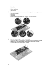
c) Lift the system board off the tape and lifting the connector latch) 5. Lift the connector latches and disconnect the following steps to remove system board: a) Loosen the captive screws that secure the system board to the palmrest assembly. Perform the following cables from the system board: a) keyboard-backlight b) touchpad c) hard drive d) keyboard (after peeling off the palmrest assembly. 26 b) Remove the screws that secure the system board to the palmrest assembly. c) hard drive d) power-adapter e) touch-panel cable f) display cable 4.
c) Lift the system board off the tape and lifting the connector latch) 5. Lift the connector latches and disconnect the following steps to remove system board: a) Loosen the captive screws that secure the system board to the palmrest assembly. Perform the following cables from the system board: a) keyboard-backlight b) touchpad c) hard drive d) keyboard (after peeling off the palmrest assembly. 26 b) Remove the screws that secure the system board to the palmrest assembly. c) hard drive d) power-adapter e) touch-panel cable f) display cable 4.
Dell Owners Manual
Page 27
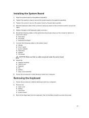
... Removing the Keyboard 1. Connect the following cables on the system board and press down on the connector latches to secure the cables: a) hard-drive b) touchpad c) keyboard-backlight 7. Peel off the Mylar sheath to secure the cable. 5. Tighten the screws to secure the system board ...to the system board: a) display b) touch-panel c) power-adapter d) hard drive e) speaker f) I/O-board CAUTION: Make sure that no cables are placed under the system board. 8. Installing the System Board 1. Install the: a) ...
... Removing the Keyboard 1. Connect the following cables on the system board and press down on the connector latches to secure the cables: a) hard-drive b) touchpad c) keyboard-backlight 7. Peel off the Mylar sheath to secure the cable. 5. Tighten the screws to secure the system board ...to the system board: a) display b) touch-panel c) power-adapter d) hard drive e) speaker f) I/O-board CAUTION: Make sure that no cables are placed under the system board. 8. Installing the System Board 1. Install the: a) ...
Dell Owners Manual
Page 29
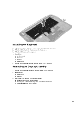
Affix the Mylar tape to the screws on the keyboard. 3. Install the: a) system board b) hard drive c) battery d) base cover 5. Follow the procedures in After Working Inside Your Computer. Remove the: a) base cover b) battery 3. Disconnect and remove the following cables: a) antenna cables ...
Affix the Mylar tape to the screws on the keyboard. 3. Install the: a) system board b) hard drive c) battery d) base cover 5. Follow the procedures in After Working Inside Your Computer. Remove the: a) base cover b) battery 3. Disconnect and remove the following cables: a) antenna cables ...
Dell Owners Manual
Page 32
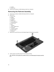
.... 32 CAUTION: Lift the palmrest assembly slowly to the palmrest assembly. 4. Follow the procedures in After Working Inside Your Computer. Remove the: a) base cover b) battery c) hard drive d) speakers e) WLAN card f) coin-cell battery g) mSATA card h) fans i) heatsink j) power-adapter port k) I/O board l) memory modules m) system board n) keyboard 3. Lift the palmrest assembly away from...
.... 32 CAUTION: Lift the palmrest assembly slowly to the palmrest assembly. 4. Follow the procedures in After Working Inside Your Computer. Remove the: a) base cover b) battery c) hard drive d) speakers e) WLAN card f) coin-cell battery g) mSATA card h) fans i) heatsink j) power-adapter port k) I/O board l) memory modules m) system board n) keyboard 3. Lift the palmrest assembly away from...

Dell Owners Manual
Page 34
Follow the procedures in After Working Inside Your Computer. 34 e) power-adapter port f) heatsink g) fans h) mSATA card i) coin-cell battery j) WLAN card k) speakers l) hard drive m) battery n) base cover 5.
Follow the procedures in After Working Inside Your Computer. 34 e) power-adapter port f) heatsink g) fans h) mSATA card i) coin-cell battery j) WLAN card k) speakers l) hard drive m) battery n) base cover 5.

Dell Owners Manual
Page 35
... key The one-time boot menu displays the devices that you make are : • Removable Drive (if available) • STXXXX Drive NOTE: XXX denotes the SATA drive number. • Optical Drive • Diagnostics NOTE: Choosing Diagnostics, will display the ePSA diagnostics screen. Navigation Keys The following...the System Setup‐defined boot device order and boot directly to a specific device (for example: optical drive or hard drive). During the Power-on Self Test (POST), when the Dell logo appears, you can : • Change the NVRAM settings after you add or remove hardware •...
... key The one-time boot menu displays the devices that you make are : • Removable Drive (if available) • STXXXX Drive NOTE: XXX denotes the SATA drive number. • Optical Drive • Diagnostics NOTE: Choosing Diagnostics, will display the ePSA diagnostics screen. Navigation Keys The following...the System Setup‐defined boot device order and boot directly to a specific device (for example: optical drive or hard drive). During the Power-on Self Test (POST), when the Dell logo appears, you can : • Change the NVRAM settings after you add or remove hardware •...

Dell Owners Manual
Page 38
... set, change , or delete the administrator (admin) password. NOTE: Deleting the admin password automatically deletes the system password and the hard drive password. NOTE: Successful password changes take effect immediately. Default Setting: Permitted Allows you to the operating system. This option is set ... Setting) Displays the status of the system password. Allows you to enable or disable permissions to set a System password and a Hard Drive password when the admin password is Enable by the operating system. Default Setting: Not set the asset tag. NOTE: Successful password ...
... set, change , or delete the administrator (admin) password. NOTE: Deleting the admin password automatically deletes the system password and the hard drive password. NOTE: Successful password changes take effect immediately. Default Setting: Permitted Allows you to the operating system. This option is set ... Setting) Displays the status of the system password. Allows you to enable or disable permissions to set a System password and a Hard Drive password when the admin password is Enable by the operating system. Default Setting: Not set the asset tag. NOTE: Successful password ...

Dell Owners Manual
Page 39
... NOTE: Disabling this option does not change any settings you may have made to find an operating system: • 1 st Boot Priority [ CD/DVD/CDRW Drive] • 2nd Boot Priority [Network] • 3rd Boot Priority [mini SSD] • 4th Boot Priority [USB Storage Device • 5th Boot Priority...
... NOTE: Disabling this option does not change any settings you may have made to find an operating system: • 1 st Boot Priority [ CD/DVD/CDRW Drive] • 2nd Boot Priority [Network] • 3rd Boot Priority [mini SSD] • 4th Boot Priority [USB Storage Device • 5th Boot Priority...

Dell Owners Manual
Page 48
... Specification 100 VAC to 240 VAC 1.80 A 50 Hz to 149 °F) 3 V CR2032 lithium-ion cell Table 20. Feature Hard Drives (optional) Solid State Drives (optional) Size: Specification one internal 2.5 inch SATA HDD One Solid State Drive (SSD), Full Mini Card (FMC) 128 GB, 256 GB, 500 GB, 512 GB, and 1 TB Table 19.
... Specification 100 VAC to 240 VAC 1.80 A 50 Hz to 149 °F) 3 V CR2032 lithium-ion cell Table 20. Feature Hard Drives (optional) Solid State Drives (optional) Size: Specification one internal 2.5 inch SATA HDD One Solid State Drive (SSD), Full Mini Card (FMC) 128 GB, 256 GB, 500 GB, 512 GB, and 1 TB Table 19.

Dell Statement of Volatility
Page 2
...Trademarks used in this text: Dell™, the DELL logo, Dell Precision™, OptiPlex™, Latitude™, PowerEdge™, PowerVault™, PowerConnect™, OpenManage™, EqualLogic™, KACE™, FlexAddress™ and Vostro™ are registered trademarks of Dell Inc. Novell® is ...solid state flash drive) and Hybrid Hard Disk Drive (HDD). AMD® is SSD (solid state flash drive). in the United States and/or other countries. in the United States and/or other countries. one . Description Hard drive(s) mSATA drive Reference Designator ...
...Trademarks used in this text: Dell™, the DELL logo, Dell Precision™, OptiPlex™, Latitude™, PowerEdge™, PowerVault™, PowerConnect™, OpenManage™, EqualLogic™, KACE™, FlexAddress™ and Vostro™ are registered trademarks of Dell Inc. Novell® is ...solid state flash drive) and Hybrid Hard Disk Drive (HDD). AMD® is SSD (solid state flash drive). in the United States and/or other countries. in the United States and/or other countries. one . Description Hard drive(s) mSATA drive Reference Designator ...


