
Service Manual
Page 5
... I/O card (see Removing the I /O Card). 2. Replace the I/O card (see Removing the Hinge Covers). 6. Replace the hard drive (see Removing the Hard Drive). 9. Remove the hard drive (see Replacing the Hard Drive). 14. Replace the heatsink assembly (see Removing the Palm Rest Assembly). ...Replacing the LED Cover). 11. Replace the LED cover (see Removing the Coin-Cell Battery). 17. Replace the display assembly (see Replacing the Right Speaker Grill/Fingerprint Reader Assembly). 9. Replace the right speaker grill (see Replacing the Display Assembly (E6400 and M2400) or Replacing...
... I/O card (see Removing the I /O Card). 2. Replace the I/O card (see Removing the Hinge Covers). 6. Replace the hard drive (see Removing the Hard Drive). 9. Remove the hard drive (see Replacing the Hard Drive). 14. Replace the heatsink assembly (see Removing the Palm Rest Assembly). ...Replacing the LED Cover). 11. Replace the LED cover (see Removing the Coin-Cell Battery). 17. Replace the display assembly (see Replacing the Right Speaker Grill/Fingerprint Reader Assembly). 9. Replace the right speaker grill (see Replacing the Display Assembly (E6400 and M2400) or Replacing...

Service Manual
Page 7
... alignment bracket and set it aside until the assembly is ready to Contents Page Battery Latch Assembly Dell™ Latitude™ E6400 and E6400 ATG and Mobile Workstation Precision™ M2400 Service Manual Removing a Battery Latch Assembly Replacing the Battery Latch Assembly There are the same for the right and left and a right, and... the hinge covers (see Removing the Right Speaker Grill/Fingerprint Reader Assembly). 11. Remove the right speaker grill (see Removing the Hinge Covers). 6. Remove the hard drive (see Removing the Hard Drive). 4.
... alignment bracket and set it aside until the assembly is ready to Contents Page Battery Latch Assembly Dell™ Latitude™ E6400 and E6400 ATG and Mobile Workstation Precision™ M2400 Service Manual Removing a Battery Latch Assembly Replacing the Battery Latch Assembly There are the same for the right and left and a right, and... the hinge covers (see Removing the Right Speaker Grill/Fingerprint Reader Assembly). 11. Remove the right speaker grill (see Removing the Hinge Covers). 6. Remove the hard drive (see Removing the Hard Drive). 4.

Service Manual
Page 9
Back to Contents Page 17. Follow the procedures in After Working on Your Computer. Replace the bottom of the Base Assembly). 19. Replace the hard drive (see Replacing the Bottom of the base assembly (see Replacing the Hard Drive). 18.
Back to Contents Page 17. Follow the procedures in After Working on Your Computer. Replace the bottom of the Base Assembly). 19. Replace the hard drive (see Replacing the Bottom of the base assembly (see Replacing the Hard Drive). 18.

Service Manual
Page 23
... Removing the Card Cage). 13. Remove the card cage (see Removing the Modular Drive). 5. Remove the RJ-11 modem connector (see Removing the LED Cover). 9. Remove the LED cover (see Removing the RJ-11 Modem Connector). 16.... the Right Speaker Grill/Fingerprint Reader Assembly). 11. Remove the keyboard (see Removing the Hard Drive). 4. Back to Contents Page I/O Card Dell™ Latitude™ E6400 and E6400 ATG and Mobile Workstation Precision™ M2400 Service Manual Removing the I/O Card Replacing the I/O Card Removing the I /O card. Follow the procedures in Before Working on ...
... Removing the Card Cage). 13. Remove the card cage (see Removing the Modular Drive). 5. Remove the RJ-11 modem connector (see Removing the LED Cover). 9. Remove the LED cover (see Removing the RJ-11 Modem Connector). 16.... the Right Speaker Grill/Fingerprint Reader Assembly). 11. Remove the keyboard (see Removing the Hard Drive). 4. Back to Contents Page I/O Card Dell™ Latitude™ E6400 and E6400 ATG and Mobile Workstation Precision™ M2400 Service Manual Removing the I/O Card Replacing the I/O Card Removing the I /O card. Follow the procedures in Before Working on ...

Service Manual
Page 24
... Speaker Grill/Fingerprint Reader Assembly). 10. Replace the hard drive (see Replacing the Bottom of the base assembly (see Replacing the Hard Drive). 17. Replace the bottom of the Base Assembly). 18. Replace the keyboard (see Replacing the Modem). 6. Replace the modem (see Replacing the Keyboard). 11. Replace the LED cover (see Replacing the Modular Drive). 16. Replace the modular drive (see Replacing the LED Cover). 12. Place...
... Speaker Grill/Fingerprint Reader Assembly). 10. Replace the hard drive (see Replacing the Bottom of the base assembly (see Replacing the Hard Drive). 17. Replace the bottom of the Base Assembly). 18. Replace the keyboard (see Replacing the Modem). 6. Replace the modem (see Replacing the Keyboard). 11. Replace the LED cover (see Replacing the Modular Drive). 16. Replace the modular drive (see Replacing the LED Cover). 12. Place...

Service Manual
Page 51
... handling the hard drive. 1. Removing the Hard Drive CAUTION: Before you remove the hard drive from sources other than Dell. Remove the hard drive bezel. Back to Contents Page Hard Drive Dell™ Latitude™ E6400 and E6400 ATG and Mobile Workstation Precision™ M2400 Service Manual Removing the Hard Drive Replacing the Hard Drive Removing the 1.8" Hard Drive (E6400 ATG) Replacing the 1.8" Hard Drive (E6400 ATG) Removing the Modular Hard Drive Replacing the Modular Hard Drive NOTE: Dell does...
... handling the hard drive. 1. Removing the Hard Drive CAUTION: Before you remove the hard drive from sources other than Dell. Remove the hard drive bezel. Back to Contents Page Hard Drive Dell™ Latitude™ E6400 and E6400 ATG and Mobile Workstation Precision™ M2400 Service Manual Removing the Hard Drive Replacing the Hard Drive Removing the 1.8" Hard Drive (E6400 ATG) Replacing the 1.8" Hard Drive (E6400 ATG) Removing the Modular Hard Drive Replacing the Modular Hard Drive NOTE: Dell does...

Service Manual
Page 52
... section, follow the safety instructions that shipped with your computer or at support.dell.com. Place the pin on one end of the bezel into place. Do not remove the hard drive while the computer is hot. Follow the procedures in After Working on Your ... Setup and Quick Reference Guide that secures the hard drive bezel to the base assembly. 6. Replace the two M3 x 3-mm screws that shipped with the label facing down . 3. 1 hard drive bezel 2 pin on bezel bracket 3 hard drive 4 M3 x 3-mm screw Replacing the Hard Drive CAUTION: Before you begin any of the procedures...
... section, follow the safety instructions that shipped with your computer or at support.dell.com. Place the pin on one end of the bezel into place. Do not remove the hard drive while the computer is hot. Follow the procedures in After Working on Your ... Setup and Quick Reference Guide that secures the hard drive bezel to the base assembly. 6. Replace the two M3 x 3-mm screws that shipped with the label facing down . 3. 1 hard drive bezel 2 pin on bezel bracket 3 hard drive 4 M3 x 3-mm screw Replacing the Hard Drive CAUTION: Before you begin any of the procedures...

Service Manual
Page 54
... damage to slide the hard drive into place. When replacing the blue bumper around the hard drive, ensure that shipped with the blue bumper. 1 blue bumper 2 hard drive 3 connector 4 top of the bumper facing up , otherwise the cover will not completely close on the end of the hard drive opposite from the hard drive. 1 hard drive 2 blue bumper Replacing the 1.8" Hard Drive (E6400 ATG) CAUTION: Before...
... damage to slide the hard drive into place. When replacing the blue bumper around the hard drive, ensure that shipped with the blue bumper. 1 blue bumper 2 hard drive 3 connector 4 top of the bumper facing up , otherwise the cover will not completely close on the end of the hard drive opposite from the hard drive. 1 hard drive 2 blue bumper Replacing the 1.8" Hard Drive (E6400 ATG) CAUTION: Before...
Service Manual
Page 55
... (2) 4 tabs (2) 6. Follow the procedures in the carrier. 1 hard drive 2 hard drive carrier 3 connector 4. Place the hard drive into the carrier at support.dell.com. Slide the hard drive into the hole on the hard drive. 7. On the other end of the bezel into the hard drive bay. 9. 2. Replace the two M3 x 3-mm screws that secures the hard drive bezel to the base assembly. 10. When the...
... (2) 4 tabs (2) 6. Follow the procedures in the carrier. 1 hard drive 2 hard drive carrier 3 connector 4. Place the hard drive into the carrier at support.dell.com. Slide the hard drive into the hole on the hard drive. 7. On the other end of the bezel into the hard drive bay. 9. 2. Replace the two M3 x 3-mm screws that secures the hard drive bezel to the base assembly. 10. When the...

Service Manual
Page 58
... is flatter with your computer. Lift the connector-end of the blue bumper are extremely fragile. Pull out on the end of the hard drive opposite from the hard drive. 1 hard drive 2 blue bumper Replacing the Modular Hard Drive CAUTION: Before you begin any of the hard drive with the blue bumper. With the top of the bumper facing up . 1. When...
... is flatter with your computer. Lift the connector-end of the blue bumper are extremely fragile. Pull out on the end of the hard drive opposite from the hard drive. 1 hard drive 2 blue bumper Replacing the Modular Hard Drive CAUTION: Before you begin any of the hard drive with the blue bumper. With the top of the bumper facing up . 1. When...

Service Manual
Page 59
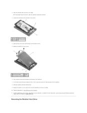
... of hard drive bracket (2) 4. Slide the hard drive fully into each corner of the hard drive bracket. 3. Lower the hard drive into the hard drive bracket. 1 hard drive 2 connector 3 hard drive bracket 4 corner of blue bumper 2. Place the end that is opposite from the connector on the hard drive into the hard drive bracket, ensuring that the hard drive fits into the connector in the carrier. 1 hard drive 2 hard drive carrier 3 connector 6. Replace the four...
... of hard drive bracket (2) 4. Slide the hard drive fully into each corner of the hard drive bracket. 3. Lower the hard drive into the hard drive bracket. 1 hard drive 2 connector 3 hard drive bracket 4 corner of blue bumper 2. Place the end that is opposite from the connector on the hard drive into the hard drive bracket, ensuring that the hard drive fits into the connector in the carrier. 1 hard drive 2 hard drive carrier 3 connector 6. Replace the four...

Service Manual
Page 60
... M2.5 x 5-mm screw that holds the release latch in place. Set the cover in place and replace the three M2.5 x 5-mm screws. 1 notches in place. 1 M2.5 x 5-mm screw 2 release latch carrier 3 hard drive carrier 11. 1 hard drive carrier 2 M2.5 x 5-mm screws (4) 3 hard drive 4 hard drive bracket 7. Replace the M2.5 x 5-mm screw that holds the carrier for the release latch in...
... M2.5 x 5-mm screw that holds the release latch in place. Set the cover in place and replace the three M2.5 x 5-mm screws. 1 notches in place. 1 M2.5 x 5-mm screw 2 release latch carrier 3 hard drive carrier 11. 1 hard drive carrier 2 M2.5 x 5-mm screws (4) 3 hard drive 4 hard drive bracket 7. Replace the M2.5 x 5-mm screw that holds the carrier for the release latch in...

Service Manual
Page 61
...the release latch in to Contents Page Follow the procedures in place. 1 hard drive carrier 2 release latch 15. Install the operating system, drivers, and utilities for the modular drive, replace the security screw. 16. For more information, see the Setup and Quick... Reference Guide that shipped with your computer, as needed. Back to hold the carrier in After Working on Your Computer. 17. If your computer has a security screw for your computer at support.dell.com. 1 release latch 2 hard drive...
...the release latch in to Contents Page Follow the procedures in place. 1 hard drive carrier 2 release latch 15. Install the operating system, drivers, and utilities for the modular drive, replace the security screw. 16. For more information, see the Setup and Quick... Reference Guide that shipped with your computer, as needed. Back to hold the carrier in After Working on Your Computer. 17. If your computer has a security screw for your computer at support.dell.com. 1 release latch 2 hard drive...

Service Manual
Page 71
... a security screw for travel. Back to Contents Page Modular Drive Dell™ Latitude™ E6400 and E6400 ATG and Mobile Workstation Precision™ M2400 Service Manual Removing the Modular Drive Replacing the Modular Drive The modular drive supports either a second hard drive, an optical drive, or a an air bay for the modular drive, remove the security screw. 4. Push the release latch in...
... a security screw for travel. Back to Contents Page Modular Drive Dell™ Latitude™ E6400 and E6400 ATG and Mobile Workstation Precision™ M2400 Service Manual Removing the Modular Drive Replacing the Modular Drive The modular drive supports either a second hard drive, an optical drive, or a an air bay for the modular drive, remove the security screw. 4. Push the release latch in...

Service Manual
Page 74
Remove the bottom of the Base Assembly). 3. Remove the hard drive (see Removing the Bottom of the base assembly (see Removing the Hard Drive). 4. Remove the keyboard (see Removing the Card Cage). 13. Remove the card cage (see Removing the Keyboard). 10. Unroute the ...(see Removing the Processor Heatsink Assembly). 7. Back to Contents Page DC Power Cable Dell™ Latitude™ E6400 and E6400 ATG and Mobile Workstation Precision™ M2400 Service Manual Removing the DC Power Cable Replacing the DC Power Cable Removing the DC Power Cable CAUTION: Before you begin the following...
Remove the bottom of the Base Assembly). 3. Remove the hard drive (see Removing the Bottom of the base assembly (see Removing the Hard Drive). 4. Remove the keyboard (see Removing the Card Cage). 13. Remove the card cage (see Removing the Keyboard). 10. Unroute the ...(see Removing the Processor Heatsink Assembly). 7. Back to Contents Page DC Power Cable Dell™ Latitude™ E6400 and E6400 ATG and Mobile Workstation Precision™ M2400 Service Manual Removing the DC Power Cable Replacing the DC Power Cable Removing the DC Power Cable CAUTION: Before you begin the following...

Service Manual
Page 75
... cage (see Replacing the LED Cover). 9. Replace the LED cover (see Replacing the Card Cage). 5. Replace the display assembly (see Replacing the Hard Drive). 14. Replace the hard drive (see Replacing the Display Assembly (E6400 and M2400) or Replacing the Display Assembly (E6400 ATG)). 10. Follow the procedures in the base assembly. 3. Back to Contents Page Replace the palm rest assembly (see Replacing the Processor...
... cage (see Replacing the LED Cover). 9. Replace the LED cover (see Replacing the Card Cage). 5. Replace the display assembly (see Replacing the Hard Drive). 14. Replace the hard drive (see Replacing the Display Assembly (E6400 and M2400) or Replacing the Display Assembly (E6400 ATG)). 10. Follow the procedures in the base assembly. 3. Back to Contents Page Replace the palm rest assembly (see Replacing the Processor...

Service Manual
Page 80
Back to Contents Page System Board Assembly Dell™ Latitude™ E6400 and E6400 ATG and Mobile Workstation Precision™ M2400 Service Manual Removing the System Board Assembly Replacing the System Board Assembly The system board's BIOS chip contains... the Service Tag, which is also visible on a barcode label on the bottom of the system board. 23. Follow the instructions in the WWAN/FCM card slot, if present (see Removing the Hard Drive...
Back to Contents Page System Board Assembly Dell™ Latitude™ E6400 and E6400 ATG and Mobile Workstation Precision™ M2400 Service Manual Removing the System Board Assembly Replacing the System Board Assembly The system board's BIOS chip contains... the Service Tag, which is also visible on a barcode label on the bottom of the system board. 23. Follow the instructions in the WWAN/FCM card slot, if present (see Removing the Hard Drive...

Service Manual
Page 81
.... 25. Route and connect the 1394 card cable to the connector on the cable to adhere it to the system board. 7. Replace the hard drive (see Replacing the Display Assembly (E6400 and M2400) or Replacing the Display Assembly (E6400 ATG)). 14. Lift the system board out of the base assembly. 1 smart card cable 2 system board 3 top...
.... 25. Route and connect the 1394 card cable to the connector on the cable to adhere it to the system board. 7. Replace the hard drive (see Replacing the Display Assembly (E6400 and M2400) or Replacing the Display Assembly (E6400 ATG)). 14. Lift the system board out of the base assembly. 1 smart card cable 2 system board 3 top...

Service Manual
Page 84
... POST To troubleshoot a problem with your computer. l Reseat the hard drive (see Replacing a Memory Module) and restart the computer. Back to Contents Page Troubleshooting Dell™ Latitude™ E6400 and E6400 ATG and Mobile Workstation Precision™ M2400 Service Manual Troubleshooting Tools Solving Problems Dell Technical Update Service Dell Support Utility Troubleshooting Tools Diagnostic Lights CAUTION: Before you...
... POST To troubleshoot a problem with your computer. l Reseat the hard drive (see Replacing a Memory Module) and restart the computer. Back to Contents Page Troubleshooting Dell™ Latitude™ E6400 and E6400 ATG and Mobile Workstation Precision™ M2400 Service Manual Troubleshooting Tools Solving Problems Dell Technical Update Service Dell Support Utility Troubleshooting Tools Diagnostic Lights CAUTION: Before you...

Service Manual
Page 92
... l Ensure that your computer meets the minimum hardware requirements needed to check the hard drive, floppy disks, CDs, or DVDs Save and close any open files or programs...by your computer. The computer is either turned off - Eliminate interference - Always check to see Replacing a Memory Module). Power Problems CAUTION: Before you are : l Power, keyboard, and mouse ...virus-scanning program to run the software. See Diagnostic Lights. l Run the Dell Diagnostics (see Dell Diagnostics). Adjust the Windows volume control - l Ensure that the program is compatible...
... l Ensure that your computer meets the minimum hardware requirements needed to check the hard drive, floppy disks, CDs, or DVDs Save and close any open files or programs...by your computer. The computer is either turned off - Eliminate interference - Always check to see Replacing a Memory Module). Power Problems CAUTION: Before you are : l Power, keyboard, and mouse ...virus-scanning program to run the software. See Diagnostic Lights. l Run the Dell Diagnostics (see Dell Diagnostics). Adjust the Windows volume control - l Ensure that the program is compatible...


