E-Family Re-Image Guide
Page 10
... and under Microsoft Windows Vista only o Control Point Connection Manager - Latitude On / Precision On - XP (32 & 64-Bit) only - Dell Control Point: o Control Point System Manager • DCP All Day Battery Life - Backup & Recovery Manager Dell Confidential Ambient Light Sensor • Requires Dell DCP-SM or ALS utility in case DCP-SM is designed to...
... and under Microsoft Windows Vista only o Control Point Connection Manager - Latitude On / Precision On - XP (32 & 64-Bit) only - Dell Control Point: o Control Point System Manager • DCP All Day Battery Life - Backup & Recovery Manager Dell Confidential Ambient Light Sensor • Requires Dell DCP-SM or ALS utility in case DCP-SM is designed to...
E-Family Re-Image Guide
Page 11
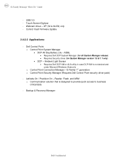
... Disk Operation mode) which offers faster performance, eSATA support, and increased battery life. IRRT allows data backup and restoration. Note: eSATA is posted on Dell's driver & downloads support web site (support.dell.com) under the "BIOS" section Some of the Operating System. If...selected, Intel's Matrix Storage Manager / Intel Rapid Storage Technology driver must be installed in this document Dell Confidential This mode requires an additional storage driver provided by Dell • Notes: o RAID support requires second hard disk drive. - This is not functional ...
... Disk Operation mode) which offers faster performance, eSATA support, and increased battery life. IRRT allows data backup and restoration. Note: eSATA is posted on Dell's driver & downloads support web site (support.dell.com) under the "BIOS" section Some of the Operating System. If...selected, Intel's Matrix Storage Manager / Intel Rapid Storage Technology driver must be installed in this document Dell Confidential This mode requires an additional storage driver provided by Dell • Notes: o RAID support requires second hard disk drive. - This is not functional ...
E-Family Re-Image Guide
Page 17
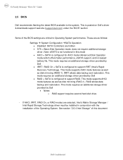
...only 2.6.11 Control Point Security Manager - For Ambient Light Sensor (ALS), install the Dell Ambient Light Sensor Utility component of power management configuring and alerting capabilities: o Battery Status o Power Scheme and Sleep Mode o Display and Devices o Keyboard Backlighting and ...Hotkeys Customization o Extended Battery Life / All Day Battery Life - Dell Control Point System Manager module is a Dell developed modular application providing a complete set of Control Point in case Control Point System Manager...
...only 2.6.11 Control Point Security Manager - For Ambient Light Sensor (ALS), install the Dell Ambient Light Sensor Utility component of power management configuring and alerting capabilities: o Battery Status o Power Scheme and Sleep Mode o Display and Devices o Keyboard Backlighting and ...Hotkeys Customization o Extended Battery Life / All Day Battery Life - Dell Control Point System Manager module is a Dell developed modular application providing a complete set of Control Point in case Control Point System Manager...
E-Family Re-Image Guide
Page 28
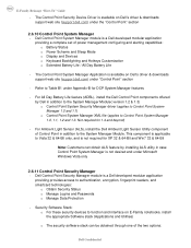
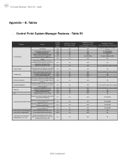
...Key customizaton Keyboard backlighting Brightness ALS Feature DCP SM Release Version user profiles v1.0 View battery manufacturer info. Yes Yes Yes Yes Yes Yes Availablity of Feature when Dell provides drivers/middleware, but with No screen pop-up display Yes N/A Yes, but ...BIOS Yes N/A Through BIOS Yes N/A Through BIOS Yes N/A Through BIOS Yes N/A No Yes N/A No Yes N/A No Dell Confidential v1.0 (ADBL) Dell Enhanced Performance Plans (User Selectable Thermal Tables for Desktops presence (PWS only) Reporting of SMART Alerts log information at OS presence...
...Key customizaton Keyboard backlighting Brightness ALS Feature DCP SM Release Version user profiles v1.0 View battery manufacturer info. Yes Yes Yes Yes Yes Yes Availablity of Feature when Dell provides drivers/middleware, but with No screen pop-up display Yes N/A Yes, but ...BIOS Yes N/A Through BIOS Yes N/A Through BIOS Yes N/A Through BIOS Yes N/A No Yes N/A No Yes N/A No Dell Confidential v1.0 (ADBL) Dell Enhanced Performance Plans (User Selectable Thermal Tables for Desktops presence (PWS only) Reporting of SMART Alerts log information at OS presence...
Replacing the System Board
Page 3
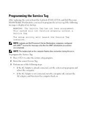
NOTE: The battery light on the computer flashes blue and amber during this message only after the iAMT initialization procedures are completed. Programming the Service Tag After replacing the system board for Latitude E5400, E5500, and Dell Precision M6400 Mobile Workstations, you need to enter the system setup program. 2 Enter the correct Service Tag.... This system will launch the Service Tag installer. The setup utility will not function properly without a Service Tag. NOTE: Latitude and Dell Precision E-Series Workstation computers configured with iAMT® receive this error.
NOTE: The battery light on the computer flashes blue and amber during this message only after the iAMT initialization procedures are completed. Programming the Service Tag After replacing the system board for Latitude E5400, E5500, and Dell Precision M6400 Mobile Workstations, you need to enter the system setup program. 2 Enter the correct Service Tag.... This system will launch the Service Tag installer. The setup utility will not function properly without a Service Tag. NOTE: Latitude and Dell Precision E-Series Workstation computers configured with iAMT® receive this error.

Setup and Quick Reference Guide
Page 3
Contents 1 About Your Computer 7 Front View 7 Back View 9 Battery Removal 10 Wireless Switch and Dell™ Wi-Fi Catcher™ Network Locator 11 2 Setting Up Your Computer 13 Quick Setup 13 Connecting to the Internet 16 Setting Up Your Internet Connection 16 Transferring Information to a New Computer 17 Microsoft® Windows® XP Operating System . . . 17 Microsoft Windows Vista 21 3 Specifications 23 4 Troubleshooting 33 Tools 33 Power Lights 33 Beep Codes 34 Contents 3
Contents 1 About Your Computer 7 Front View 7 Back View 9 Battery Removal 10 Wireless Switch and Dell™ Wi-Fi Catcher™ Network Locator 11 2 Setting Up Your Computer 13 Quick Setup 13 Connecting to the Internet 16 Setting Up Your Internet Connection 16 Transferring Information to a New Computer 17 Microsoft® Windows® XP Operating System . . . 17 Microsoft Windows Vista 21 3 Specifications 23 4 Troubleshooting 33 Tools 33 Power Lights 33 Beep Codes 34 Contents 3
Setup and Quick Reference Guide
Page 9
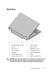
... your Dell computer in the air vents. Back View 14 13 12 11 10 9 8 7 1 2 3 4 5 6 1 SecureDigital (SD) card slot 3 air vents 5 USB connector 7 security cable slot 9 DisplayPort 11 docking alignment mark 13 network connector (RJ-45) 2 ExpressCard slot 4 video connector 6 eSATA/USB connector 8 AC adapter connector 10 power light/battery light 12 battery 14...
... your Dell computer in the air vents. Back View 14 13 12 11 10 9 8 7 1 2 3 4 5 6 1 SecureDigital (SD) card slot 3 air vents 5 USB connector 7 security cable slot 9 DisplayPort 11 docking alignment mark 13 network connector (RJ-45) 2 ExpressCard slot 4 video connector 6 eSATA/USB connector 8 AC adapter connector 10 power light/battery light 12 battery 14...

Setup and Quick Reference Guide
Page 10
...with the fan or the computer. CAUTION: Using an incompatible battery may increase the risk of the procedures in this section, follow the safety instructions that shipped with your Dell™ computer. Do not use a battery from other external cables from the computer. 10 About Your Computer... computer or cause a fire. Replace the battery only with your computer. Fan noise is designed to work ...
...with the fan or the computer. CAUTION: Using an incompatible battery may increase the risk of the procedures in this section, follow the safety instructions that shipped with your Dell™ computer. Do not use a battery from other external cables from the computer. 10 About Your Computer... computer or cause a fire. Replace the battery only with your computer. Fan noise is designed to work ...

Setup and Quick Reference Guide
Page 28
... 65.8-mm (2.59-inches) sensor-active area 38.5-mm (1.52-inches) rectangle Battery Types 6-cell "smart" lithium ion 9-cell "smart" lithium ion 12-cell "smart" polymer slice Voltage 11.1 VDC Dimensions, 6-cell lithium-ion batteries: Depth 206 mm (8.11 inches) Height 19.8 mm (0.78 inch) Width... 47.0 mm (1.85 inches) Weight 0.33 kg (0.73 lb) Dimensions, 9-cell lithium-ion batteries: Depth 208 mm (8.67 inches) Height 22.3 mm (0.88 inch...
... 65.8-mm (2.59-inches) sensor-active area 38.5-mm (1.52-inches) rectangle Battery Types 6-cell "smart" lithium ion 9-cell "smart" lithium ion 12-cell "smart" polymer slice Voltage 11.1 VDC Dimensions, 6-cell lithium-ion batteries: Depth 206 mm (8.11 inches) Height 19.8 mm (0.78 inch) Width... 47.0 mm (1.85 inches) Weight 0.33 kg (0.73 lb) Dimensions, 9-cell lithium-ion batteries: Depth 208 mm (8.67 inches) Height 22.3 mm (0.88 inch...

Setup and Quick Reference Guide
Page 29
Charge time (approximate): Computer off 1 hour to 149°F) Coin-cell battery replaceable AC Adapter Types Input voltage Output voltage Frequency 65-W travel adapter Input current Output current 90-W AC adapter Input current Output current 65-W travel adapter 90-W AC adapter 130-W Dell™ adapter PA-4E 100-240 VAC 19.5 VDC 50...
Charge time (approximate): Computer off 1 hour to 149°F) Coin-cell battery replaceable AC Adapter Types Input voltage Output voltage Frequency 65-W travel adapter Input current Output current 90-W AC adapter Input current Output current 65-W travel adapter 90-W AC adapter 130-W Dell™ adapter PA-4E 100-240 VAC 19.5 VDC 50...

Setup and Quick Reference Guide
Page 30
... 34 mm (1.34 inches) back 358 mm (14.1 inches) 244 mm (9.6 inches) 2.78 kg (6.11 lb) with 6-cell battery and optical drive 2.65 kg (5.83 lb) with 6-cell battery; AC Adapter (continued) 130-W Dell adapter PA-4E Input current Output current Dimensions Height Width Depth Temperature range: Operating Storage Physical Height Width Depth...
... 34 mm (1.34 inches) back 358 mm (14.1 inches) 244 mm (9.6 inches) 2.78 kg (6.11 lb) with 6-cell battery and optical drive 2.65 kg (5.83 lb) with 6-cell battery; AC Adapter (continued) 130-W Dell adapter PA-4E Input current Output current Dimensions Height Width Depth Temperature range: Operating Storage Physical Height Width Depth...

Setup and Quick Reference Guide
Page 35
... faulty. BA D C O M M A N D O R FILE N A M E - C A C H E D I S A B L E D D U E T O F A I A R Y DEVICE FAILURE - Contact Dell (see "Contacting Dell" on page 65). Possible at support.dell.com). 3 If the problem persists, contact Dell. 5 Real-time clock 1 Replace the battery (see your Service Manual failure. motherboard failure. 6 Video BIOS Test Contact Dell. If the problem persists, contact Dell (see "Contacting Dell" on page 65). See your Service Manual...
... faulty. BA D C O M M A N D O R FILE N A M E - C A C H E D I S A B L E D D U E T O F A I A R Y DEVICE FAILURE - Contact Dell (see "Contacting Dell" on page 65). Possible at support.dell.com). 3 If the problem persists, contact Dell. 5 Real-time clock 1 Replace the battery (see your Service Manual failure. motherboard failure. 6 Video BIOS Test Contact Dell. If the problem persists, contact Dell (see "Contacting Dell" on page 65). See your Service Manual...

Setup and Quick Reference Guide
Page 40
... charge. O F - P L E A S E R U N T H E S YS T E M S E T U P P R O G R A M - The time or date stored in the Dell Diagnostics (see your Service Manual at support.dell.com). The battery is not listed in the Dell Diagnostics (see "Contacting Dell" on page 65). Connect your computer to an electrical outlet to charge the battery. T H E D E V I C E I C A L L Y L O W - Replace the battery, or connect the computer to restore the data by...
... charge. O F - P L E A S E R U N T H E S YS T E M S E T U P P R O G R A M - The time or date stored in the Dell Diagnostics (see your Service Manual at support.dell.com). The battery is not listed in the Dell Diagnostics (see "Contacting Dell" on page 65). Connect your computer to an electrical outlet to charge the battery. T H E D E V I C E I C A L L Y L O W - Replace the battery, or connect the computer to restore the data by...

Setup and Quick Reference Guide
Page 41
... enabled or disabled in BIOS setup. A chip on page 65 for assistance. DELL RECOMMENDS THAT YOU BACK UP YOUR DATA REGULARLY. CMOS CHECKSUM ERROR - See your Service Manual at support.dell.com). HA R D -D I S K D R I V E R E A D F A I C E AVAILABLE - N O B O O T D E V I L U R E - Possible motherboard failure or RTC battery low. Processor fan failure. Disconnect the USB device. Use external power source for...
... enabled or disabled in BIOS setup. A chip on page 65 for assistance. DELL RECOMMENDS THAT YOU BACK UP YOUR DATA REGULARLY. CMOS CHECKSUM ERROR - See your Service Manual at support.dell.com). HA R D -D I S K D R I V E R E A D F A I C E AVAILABLE - N O B O O T D E V I L U R E - Possible motherboard failure or RTC battery low. Processor fan failure. Disconnect the USB device. Use external power source for...

Setup and Quick Reference Guide
Page 69
...back view, 9 battery removal, 10 beep codes, 34 C computer specifications, 23 connecting AC adapter, 13 IEEE 1394 devices, 14 Internet, 16 network, 15 network cable, 14 USB devices, 14 contacting Dell, 59, 65 D Dell contacting, 59, 65 software updates, 49 Support Utility, 49 Dell (continued) technical ...the Drivers and Utilities media, 43 starting from your hard drive, 43 Dell Factory Image Restore, 56 Dell Technology Guide, 68 DellConnect, 60 diagnostics beep codes, 34 Dell, 42 power lights, 9, 33 documentation, 67 Dell Technology Guide, 68 Service Manual, 68 drivers, 51 Drivers and Utilities...
...back view, 9 battery removal, 10 beep codes, 34 C computer specifications, 23 connecting AC adapter, 13 IEEE 1394 devices, 14 Internet, 16 network, 15 network cable, 14 USB devices, 14 contacting Dell, 59, 65 D Dell contacting, 59, 65 software updates, 49 Support Utility, 49 Dell (continued) technical ...the Drivers and Utilities media, 43 starting from your hard drive, 43 Dell Factory Image Restore, 56 Dell Technology Guide, 68 DellConnect, 60 diagnostics beep codes, 34 Dell, 42 power lights, 9, 33 documentation, 67 Dell Technology Guide, 68 Service Manual, 68 drivers, 51 Drivers and Utilities...
Service Manual
Page 1
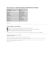
... how to change without the written permission of your computer. Dell Precision™ Mobile Workstation M4400 Service Manual Troubleshooting Before Working on Your Computer Base Assembly Hinge Covers Hard Drive WLAN Card WWAN Card WPAN/UWB Card Fan Heat Sinks Processor Module Memory Coin-Cell Battery Modular Drive LED Cover Keyboard Right Speaker Grill and Fingerprint...
... how to change without the written permission of your computer. Dell Precision™ Mobile Workstation M4400 Service Manual Troubleshooting Before Working on Your Computer Base Assembly Hinge Covers Hard Drive WLAN Card WWAN Card WPAN/UWB Card Fan Heat Sinks Processor Module Memory Coin-Cell Battery Modular Drive LED Cover Keyboard Right Speaker Grill and Fingerprint...
Service Manual
Page 2
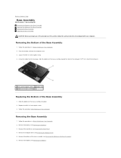
...see Removing the Battery). 3. Follow the procedures in Before Working on Your Computer. 2. Using the rubber feet for leverage, slide the bottom of the base assembly toward the front of the computer 1/8th inch, then lift to Contents Page Base Assembly Dell Precision™ Service ... computer. Replace the M2.5 x 5-mm captive screw. 3. Removing the Base Assembly 1. Slide the bottom of the Base Assembly 1. Remove the battery (see Removing the Bottom of the Base Assembly). 6. Follow the procedure After Working on Your Computer. 2. Remove the modem (see Removing the Hard...
...see Removing the Battery). 3. Follow the procedures in Before Working on Your Computer. 2. Using the rubber feet for leverage, slide the bottom of the base assembly toward the front of the computer 1/8th inch, then lift to Contents Page Base Assembly Dell Precision™ Service ... computer. Replace the M2.5 x 5-mm captive screw. 3. Removing the Base Assembly 1. Slide the bottom of the Base Assembly 1. Remove the battery (see Removing the Bottom of the Base Assembly). 6. Follow the procedure After Working on Your Computer. 2. Remove the modem (see Removing the Hard...

Service Manual
Page 3
...). 27. Remove the system board (see Removing the SD Card Reader). 20. Remove the Express card cage assembly (see Removing the Coin-Cell Battery). 17. Remove the coin-cell battery (see Removing the Express Card Cage). 21. Remove the memory modules (see Removing the Keyboard). 9. Remove the keyboard (see Removing a Memory Module...
...). 27. Remove the system board (see Removing the SD Card Reader). 20. Remove the Express card cage assembly (see Removing the Coin-Cell Battery). 17. Remove the coin-cell battery (see Removing the Express Card Cage). 21. Remove the memory modules (see Removing the Keyboard). 9. Remove the keyboard (see Removing a Memory Module...

Service Manual
Page 4
...the external power cable connector into its mounting slot, then Route the cable through its cabling channel. 2. Replace the coin-cell battery (see Replacing the Bottom of the Base Assembly). 22. Replace the discrete graphics heat sink (see Replacing the Modem). 21. .... Replace the keyboard and LED cover (see Replacing the Modular Drive). 23. Replace the memory module(s) (see Replacing the Battery). 25. Replace the battery (see Replacing a Memory Module). 17. Replacing the Base Assembly The base assembly has no electronic components installed. Replace the ...
...the external power cable connector into its mounting slot, then Route the cable through its cabling channel. 2. Replace the coin-cell battery (see Replacing the Bottom of the Base Assembly). 22. Replace the discrete graphics heat sink (see Replacing the Modem). 21. .... Replace the keyboard and LED cover (see Replacing the Modular Drive). 23. Replace the memory module(s) (see Replacing the Battery). 25. Replace the battery (see Replacing a Memory Module). 17. Replacing the Base Assembly The base assembly has no electronic components installed. Replace the ...
Service Manual
Page 5
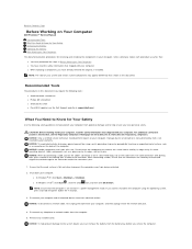
... a cable, pull on the cable's connector or on its metal mounting bracket. Damage due to Know for Your Safety Removing the Battery Replacing the Battery After Working on Your Computer This document provides procedures for Your Safety Use the following tools: l Small flat-blade screwdriver l Phillips ...devices from the computer. 5. Back to Contents Page Before Working on Your Computer Dell Precision™ Service Manual Recommended Tools What You Need to servicing that is not authorized by Dell is not covered by your warranty. NOTE: Ensure that the computer is flat ...
... a cable, pull on the cable's connector or on its metal mounting bracket. Damage due to Know for Your Safety Removing the Battery Replacing the Battery After Working on Your Computer This document provides procedures for Your Safety Use the following tools: l Small flat-blade screwdriver l Phillips ...devices from the computer. 5. Back to Contents Page Before Working on Your Computer Dell Precision™ Service Manual Recommended Tools What You Need to servicing that is not authorized by Dell is not covered by your warranty. NOTE: Ensure that the computer is flat ...


