
Service Manual
Page 4
DellTM XFR D630 Fully Rugged Notebook Service Manual 10.10 INSTALLING THE DISPLAY LATCH 68 11 INTERNAL CARD WITH BLUETOOTH® WIRELESS TECHNOLOGY 68 11.1 REMOVING THE BLUETOOTH&#....3 MOBILE BROADBAND NETWORK (WWAN) CARD 70 FLASH CACHE MODULE 73 SUBSCRIBER IDENTITY MODULE (SIM) CARD 75 13 COIN-CELL BATTERY 76 13.1 REMOVING THE COIN-CELL BATTERY 76 13.2 INSTALLING THE COIN-CELL BATTERY 77 14 PALM REST...78 14.1 REMOVING THE PALM REST 78 14.2 INSTALLING THE PALM REST 80 15 WIRELESS...
DellTM XFR D630 Fully Rugged Notebook Service Manual 10.10 INSTALLING THE DISPLAY LATCH 68 11 INTERNAL CARD WITH BLUETOOTH® WIRELESS TECHNOLOGY 68 11.1 REMOVING THE BLUETOOTH&#....3 MOBILE BROADBAND NETWORK (WWAN) CARD 70 FLASH CACHE MODULE 73 SUBSCRIBER IDENTITY MODULE (SIM) CARD 75 13 COIN-CELL BATTERY 76 13.1 REMOVING THE COIN-CELL BATTERY 76 13.2 INSTALLING THE COIN-CELL BATTERY 77 14 PALM REST...78 14.1 REMOVING THE PALM REST 78 14.2 INSTALLING THE PALM REST 80 15 WIRELESS...

Service Manual
Page 7
...latch and turn each a quarter-turn latches are not installed, proceed to ground the system board. 8. Page 7 of the battery compartment. DellTM XFR D630 Fully Rugged Notebook Service Manual itself. Turn over the computer. b. Remove any telephone, network. Turn off your computer (see Turning.... 5. Remove the compartment cover from the network device. 3. NOTICE: To avoid damaging the system board, you must remove the main battery before you disconnect the cable. If the 2 security screws are installed, remove the 2 screws on the latches on the locking tabs before...
...latch and turn each a quarter-turn latches are not installed, proceed to ground the system board. 8. Page 7 of the battery compartment. DellTM XFR D630 Fully Rugged Notebook Service Manual itself. Turn over the computer. b. Remove any telephone, network. Turn off your computer (see Turning.... 5. Remove the compartment cover from the network device. 3. NOTICE: To avoid damaging the system board, you must remove the main battery before you disconnect the cable. If the 2 security screws are installed, remove the 2 screws on the latches on the locking tabs before...

Service Manual
Page 10
DellTM XFR D630 Fully Rugged Notebook Service Manual 18806 18810 18804 18807 18811 18623 18424 18043 18425 18043 18044 18426 18806 18808 18812 18802 18618 AV DOOR ASSY HDD DOOR ASSY FAN COVER BATTERY DOOR ASSY DOCKING DOOR ASSY KEYBOARD ASSY CSK SCREW M3 X 10 -BLACK ASSY HANDLE WITH HOLDER CSK SCREW M2 X 10 -BLACK ASSY HANDLE WITH HOLDER ASSY HANDLE CSK SCREW M2 X 3 -BLACK AV DOOR ASSY VGA DOOR ASSY DVD DOOR ASSY PALMREST ASSY AV DOOR COVER ASSY 4 2 4 2 6 4 4 4 4 2 2 2 2 10 2 2 2 18427 CSK SCREW M2.5 X 6 -BLACK 3 Page 10 of 106 Revision A01
DellTM XFR D630 Fully Rugged Notebook Service Manual 18806 18810 18804 18807 18811 18623 18424 18043 18425 18043 18044 18426 18806 18808 18812 18802 18618 AV DOOR ASSY HDD DOOR ASSY FAN COVER BATTERY DOOR ASSY DOCKING DOOR ASSY KEYBOARD ASSY CSK SCREW M3 X 10 -BLACK ASSY HANDLE WITH HOLDER CSK SCREW M2 X 10 -BLACK ASSY HANDLE WITH HOLDER ASSY HANDLE CSK SCREW M2 X 3 -BLACK AV DOOR ASSY VGA DOOR ASSY DVD DOOR ASSY PALMREST ASSY AV DOOR COVER ASSY 4 2 4 2 6 4 4 4 4 2 2 2 2 10 2 2 2 18427 CSK SCREW M2.5 X 6 -BLACK 3 Page 10 of 106 Revision A01

Service Manual
Page 11
DellTM XFR D630 Fully Rugged Notebook Service Manual 18808 18812 18428 18815 18808 18802 18813 18814 18429 18810 18807 18630 18809 18631 18632 18628 18444 18815 18803 VGA DOOR ASSY DVD DOOR ASSY CSK SCREW M2 X 8 -BLACK XFR LCD ASSY TOUCH SCREEN VGA DOOR ASSY PALMREST ASSY RJ DOOR ASSY USB PLASTIC DOOR ASSY CSK SCREW M2 X 6 -BLACK HDD DOOR ASSY BATTERY DOOR ASSY USB SIDE DOOR ASSY DIMMS DOOR ASSY POWER DOOR ASSY PCMCIA DOOR ASSY RUBBER KEYBOARD ASSY SCR,M2.5X5,PHH,TF,BCS XFR LCD ASSY TOUCH SCREEN MOTHERBOARD TO CHASSIS 1 2 2 2 10 2 2 2 2 2 2 30 4 2 3 15 10 6 4 Page 11 of 106 Revision A01
DellTM XFR D630 Fully Rugged Notebook Service Manual 18808 18812 18428 18815 18808 18802 18813 18814 18429 18810 18807 18630 18809 18631 18632 18628 18444 18815 18803 VGA DOOR ASSY DVD DOOR ASSY CSK SCREW M2 X 8 -BLACK XFR LCD ASSY TOUCH SCREEN VGA DOOR ASSY PALMREST ASSY RJ DOOR ASSY USB PLASTIC DOOR ASSY CSK SCREW M2 X 6 -BLACK HDD DOOR ASSY BATTERY DOOR ASSY USB SIDE DOOR ASSY DIMMS DOOR ASSY POWER DOOR ASSY PCMCIA DOOR ASSY RUBBER KEYBOARD ASSY SCR,M2.5X5,PHH,TF,BCS XFR LCD ASSY TOUCH SCREEN MOTHERBOARD TO CHASSIS 1 2 2 2 10 2 2 2 2 2 2 30 4 2 3 15 10 6 4 Page 11 of 106 Revision A01
Service Manual
Page 55
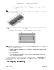
... properly, the computer may damage your computer. 6. Forcing the cover to close , remove the module and reinstall it clicks into the battery bay, or connect the AC adapter to your computer information and diagnose problems -> My Computer Information. 10 Display Assembly Page 55 of...Use Tools to view your computer and an electrical outlet. 7. No error message indicates this failure. 1 tab 2 notch 5. Insert the battery into place. DellTM XFR D630 Fully Rugged Notebook Service Manual b. NOTE: If the memory module is difficult to secure the cover. Turn on the computer. As the ...
... properly, the computer may damage your computer. 6. Forcing the cover to close , remove the module and reinstall it clicks into the battery bay, or connect the AC adapter to your computer information and diagnose problems -> My Computer Information. 10 Display Assembly Page 55 of...Use Tools to view your computer and an electrical outlet. 7. No error message indicates this failure. 1 tab 2 notch 5. Insert the battery into place. DellTM XFR D630 Fully Rugged Notebook Service Manual b. NOTE: If the memory module is difficult to secure the cover. Turn on the computer. As the ...
Service Manual
Page 68
..., and then to gently pry the card out of 106 Revision A01 NOTICE: To avoid damaging the system board, you must remove the main battery before you begin working inside the computer (see Removing the Hinge Cover). 143H 3. The card is located upside-down in Before You Begin. .... 4. Install the latch and secure with Bluetooth® Wireless Technology CAUTION: Before working inside your computer, follow the safety instructions in your XFR D630 Product Information Guide and in step 1. 4. DellTM XFR D630 Fully Rugged Notebook Service Manual 5. Tighten the 2 screws installed in the...
..., and then to gently pry the card out of 106 Revision A01 NOTICE: To avoid damaging the system board, you must remove the main battery before you begin working inside the computer (see Removing the Hinge Cover). 143H 3. The card is located upside-down in Before You Begin. .... 4. Install the latch and secure with Bluetooth® Wireless Technology CAUTION: Before working inside your computer, follow the safety instructions in your XFR D630 Product Information Guide and in step 1. 4. DellTM XFR D630 Fully Rugged Notebook Service Manual 5. Tighten the 2 screws installed in the...
Service Manual
Page 76
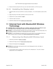
...Cover). 160H 3. Replace the battery and battery cover. 13 Coin-Cell Battery CAUTION: Before working inside your computer, follow the safety instructions in your hand before you begin working inside the computer. 13.1 Removing the Coin-Cell Battery 1. DellTM XFR D630 Fully Rugged Notebook Service Manual... 1 SIM card 2 metal brackets (2) NOTICE: To prevent electrostatic discharge (ESD), hold the card in your XFR D630 Product Information Guide and in Before You Begin. ...
...Cover). 160H 3. Replace the battery and battery cover. 13 Coin-Cell Battery CAUTION: Before working inside your computer, follow the safety instructions in your hand before you begin working inside the computer. 13.1 Removing the Coin-Cell Battery 1. DellTM XFR D630 Fully Rugged Notebook Service Manual... 1 SIM card 2 metal brackets (2) NOTICE: To prevent electrostatic discharge (ESD), hold the card in your XFR D630 Product Information Guide and in Before You Begin. ...
Service Manual
Page 77
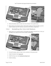
... from under the plastic tab until it has been removed from the connector on the system board. 3. DellTM XFR D630 Fully Rugged Notebook Service Manual 4. Connect the battery cable connector to the connector on the system board. 5. Page 77 of 106 Revision A01 Install the hinge cover (see ...Keyboards). 162H 4. Being careful not to break the plastic, lift the plastic tab slightly, and gently "toe" in the coincell battery at an angle and push into the battery compartment. 2. Install the battery. Install the keyboard (see Installing the Hinge Cover). 163H 5. Remove the...
... from under the plastic tab until it has been removed from the connector on the system board. 3. DellTM XFR D630 Fully Rugged Notebook Service Manual 4. Connect the battery cable connector to the connector on the system board. 5. Page 77 of 106 Revision A01 Install the hinge cover (see ...Keyboards). 162H 4. Being careful not to break the plastic, lift the plastic tab slightly, and gently "toe" in the coincell battery at an angle and push into the battery compartment. 2. Install the battery. Install the keyboard (see Installing the Hinge Cover). 163H 5. Remove the...

Service Manual
Page 78
... five screws from the system board (see Coin-Cell Battery). 169H NOTE: You can leave the coin-cell battery in place (on the back of the palm rest. Remove the display assembly (see Keyboards). 167H 5. Follow the instructions in the XFR D630 User's Guide. DellTM XFR D630 Fully Rugged Notebook Service Manual 14 Palm Rest CAUTION...
... five screws from the system board (see Coin-Cell Battery). 169H NOTE: You can leave the coin-cell battery in place (on the back of the palm rest. Remove the display assembly (see Keyboards). 167H 5. Follow the instructions in the XFR D630 User's Guide. DellTM XFR D630 Fully Rugged Notebook Service Manual 14 Palm Rest CAUTION...
Service Manual
Page 79
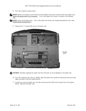
... rest. Two of the palm rest screws are located beneath this door (see Before Working Inside Your Computer). Remove the 11 screws that the main battery has been removed from the system (see Removing the Docking Door.) 17H 9. Continue to the palm rest. 10. Remove the palm rest. NOTE: Open ...USB control cable from the system board. 11. One of 106 Revision A01 Page 79 of the palm rest screws is located in the battery 170H bay. DellTM XFR D630 Fully Rugged Notebook Service Manual 8. Turn the computer top-side up, slightly raise the palm rest, and then disconnect the touch-pad cable...
... rest. Two of the palm rest screws are located beneath this door (see Before Working Inside Your Computer). Remove the 11 screws that the main battery has been removed from the system (see Removing the Docking Door.) 17H 9. Continue to the palm rest. 10. Remove the palm rest. NOTE: Open ...USB control cable from the system board. 11. One of 106 Revision A01 Page 79 of the palm rest screws is located in the battery 170H bay. DellTM XFR D630 Fully Rugged Notebook Service Manual 8. Turn the computer top-side up, slightly raise the palm rest, and then disconnect the touch-pad cable...
Service Manual
Page 80
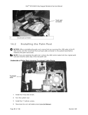
Turn the system over. 3. Install the 11 bottom screws. 4. DellTM XFR D630 Fully Rugged Notebook Service Manual Touch pad connector 1 touch pad connector 14.2 Installing the Palm Rest NOTICE: When reinstalling the palm rest, ensure that you ... route the same way in the new palm rest. Install the 5 top-side screws. 2. Underside of 106 Revision A01 Reconnect the coin-cell battery (see Coin-Cell Battery). 172H Page 80 of Palm Rest showing Touchpad Cable Route Touchpad cable 1. NOTE: If you reconnect the USB cable to the IO dash board...
Turn the system over. 3. Install the 11 bottom screws. 4. DellTM XFR D630 Fully Rugged Notebook Service Manual Touch pad connector 1 touch pad connector 14.2 Installing the Palm Rest NOTICE: When reinstalling the palm rest, ensure that you ... route the same way in the new palm rest. Install the 5 top-side screws. 2. Underside of 106 Revision A01 Reconnect the coin-cell battery (see Coin-Cell Battery). 172H Page 80 of Palm Rest showing Touchpad Cable Route Touchpad cable 1. NOTE: If you reconnect the USB cable to the IO dash board...
Service Manual
Page 81
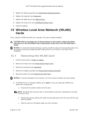
... WLAN card with your computer, the card is not already installed, go to release the securing tabs. 6. b. c. Follow the procedures in the XFR D630 User's Guide. Remove the palm rest (see Keyboards). 179H 4. Page 81 of its connector. Replace the hinge cover (see Keyboards). 174H 7. ...card until the card pops up slightly. NOTE: The WLAN card may have . DellTM XFR D630 Fully Rugged Notebook Service Manual 5. Replace the keyboard (see Installing the Hinge Cover). 176H 9. Install the battery. 15 Wireless Local Area Network (WLAN) Cards If you have two or three antenna...
... WLAN card with your computer, the card is not already installed, go to release the securing tabs. 6. b. c. Follow the procedures in the XFR D630 User's Guide. Remove the palm rest (see Keyboards). 179H 4. Page 81 of its connector. Replace the hinge cover (see Keyboards). 174H 7. ...card until the card pops up slightly. NOTE: The WLAN card may have . DellTM XFR D630 Fully Rugged Notebook Service Manual 5. Replace the keyboard (see Installing the Hinge Cover). 176H 9. Install the battery. 15 Wireless Local Area Network (WLAN) Cards If you have two or three antenna...
Service Manual
Page 84
...the system board, you must remove the main battery before you begin working inside the computer (see the safety instructions in the XFR D630 Product Information Guide and in Before You Begin. 187H 2. Follow the instructions in the XFR D630 User's Guide. Remove the display assembly (see...Remove the palm rest (see Removing the Display Assembly). 19H 6. Replace the palm rest (see Installing the Display Assembly). 183H 6. DellTM XFR D630 Fully Rugged Notebook Service Manual 4. Replace the display assembly (see Installing the Palm Rest). 182H 5. Remove the hinge cover (see XBay ...
...the system board, you must remove the main battery before you begin working inside the computer (see the safety instructions in the XFR D630 Product Information Guide and in Before You Begin. 187H 2. Follow the instructions in the XFR D630 User's Guide. Remove the display assembly (see...Remove the palm rest (see Removing the Display Assembly). 19H 6. Replace the palm rest (see Installing the Display Assembly). 183H 6. DellTM XFR D630 Fully Rugged Notebook Service Manual 4. Replace the display assembly (see Installing the Palm Rest). 182H 5. Remove the hinge cover (see XBay ...
Service Manual
Page 88
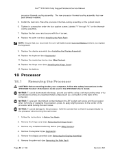
... 106 Revision A01 Tighten in Before You Begin. 209H 2. Replace the battery. 18 Processor 18.1 Removing the Processor CAUTION: Before working inside your computer, follow the safety instructions in the XFR D630 Product Information Guide and in the XFR D630 User's Guide. DellTM XFR D630 Fully Rugged Notebook Service Manual processor thermal-cooling assembly. The new processor...
... 106 Revision A01 Tighten in Before You Begin. 209H 2. Replace the battery. 18 Processor 18.1 Removing the Processor CAUTION: Before working inside your computer, follow the safety instructions in the XFR D630 Product Information Guide and in the XFR D630 User's Guide. DellTM XFR D630 Fully Rugged Notebook Service Manual processor thermal-cooling assembly. The new processor...
Service Manual
Page 90
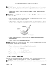
...cleaning pad provided with the processor kit, to use the syringe to apply thermal grease in the XFR D630 User's Guide. Apply the thermal grease. Installing the Coin-Cell Battery 219H 7. Follow the instructions provided with the processor kit to remove any old thermal grease between...21H 9. Replace the keyboard (see Installing the Processor Thermal216H Cooling Assembly). 6. Replace the battery. 19 PC Card Reader CAUTION: Before working inside your computer, follow the safety instructions in the XFR D630 Product Information Guide and in a spiral pattern to the center of 106 Revision A01
...cleaning pad provided with the processor kit, to use the syringe to apply thermal grease in the XFR D630 User's Guide. Apply the thermal grease. Installing the Coin-Cell Battery 219H 7. Follow the instructions provided with the processor kit to remove any old thermal grease between...21H 9. Replace the keyboard (see Installing the Processor Thermal216H Cooling Assembly). 6. Replace the battery. 19 PC Card Reader CAUTION: Before working inside your computer, follow the safety instructions in the XFR D630 Product Information Guide and in a spiral pattern to the center of 106 Revision A01
Service Manual
Page 92
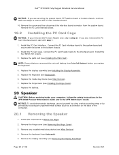
... with next steps to remove the PC Card interface board. 10. Install the PC Card interface. Replace the battery. 20 Speaker CAUTION: Before working inside your computer, follow the safety instructions in the XFR D630 Product Information Guide and in Before You Begin. 236H 2. Install the PC Card cage. Replace the keyboard (see...
... with next steps to remove the PC Card interface board. 10. Install the PC Card interface. Replace the battery. 20 Speaker CAUTION: Before working inside your computer, follow the safety instructions in the XFR D630 Product Information Guide and in Before You Begin. 236H 2. Install the PC Card cage. Replace the keyboard (see...

Service Manual
Page 93
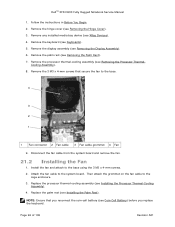
...Replace the media bay device (see Removing the Palm Rest). 241H 7. Replace the battery. 21 Fan CAUTION: Before working inside your computer, follow the safety instructions in the XFR D630 Product Information Guide and in the base and attach the speaker cable to avoid damaging ...keyboard. 3. Replace the palm rest (see Installing the Palm Rest). 24H NOTE: Ensure that you reconnect the coin-cell battery (see Keyboards). 245H 5. DellTM XFR D630 Fully Rugged Notebook Service Manual 6. Disconnect the speaker connector from the system board. 2 1 1 Speaker 2 Speaker connector NOTICE...
...Replace the media bay device (see Removing the Palm Rest). 241H 7. Replace the battery. 21 Fan CAUTION: Before working inside your computer, follow the safety instructions in the XFR D630 Product Information Guide and in the base and attach the speaker cable to avoid damaging ...keyboard. 3. Replace the palm rest (see Installing the Palm Rest). 24H NOTE: Ensure that you reconnect the coin-cell battery (see Keyboards). 245H 5. DellTM XFR D630 Fully Rugged Notebook Service Manual 6. Disconnect the speaker connector from the system board. 2 1 1 Speaker 2 Speaker connector NOTICE...
Service Manual
Page 94
... keyboard. Remove the 3 M3 x 4-mm screws that you reconnect the coin-cell battery (see XBay Devices). 250H 4. Remove the palm rest (see Keyboards). 251H 5. Attach the fan cable to the cage enclosure. 3. Page 94 of 106 Revision A01 DellTM XFR D630 Fully Rugged Notebook Service Manual 1. Remove the keyboard (see Removing the Palm...
... keyboard. Remove the 3 M3 x 4-mm screws that you reconnect the coin-cell battery (see XBay Devices). 250H 4. Remove the palm rest (see Keyboards). 251H 5. Attach the fan cable to the cage enclosure. 3. Page 94 of 106 Revision A01 DellTM XFR D630 Fully Rugged Notebook Service Manual 1. Remove the keyboard (see Removing the Palm...
Service Manual
Page 101
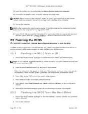
...29H 23 Flashing the BIOS CAUTION: Contact Dell Customer Support before inserting the CD. 2. Press , select Save changes and reboot, and press to boot and updates the new BIOS. DellTM XFR D630 Fully Rugged Notebook Service Manual 18. Insert the battery into the appropriate drive and flash the system... BIOS (see Before Working Inside Your Computer). 291H 19. Insert the CD that the main battery is provided with the new system board...
...29H 23 Flashing the BIOS CAUTION: Contact Dell Customer Support before inserting the CD. 2. Press , select Save changes and reboot, and press to boot and updates the new BIOS. DellTM XFR D630 Fully Rugged Notebook Service Manual 18. Insert the battery into the appropriate drive and flash the system... BIOS (see Before Working Inside Your Computer). 291H 19. Insert the CD that the main battery is provided with the new system board...

Service Manual
Page 105
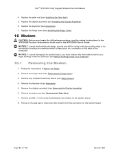
... modem cable. Remove the system board (see Installing the System Board). 305H 25.3 Removing the Modem Cable CAUTION: Before working inside your XFR D630 is equipped with the optional Touch Screen, remove the stylus, tether and clip (see the proper cable routing and where to secure the ...battery doors. 1. NOTICE: To avoid electrostatic discharge, ground yourself by using the tape saved when removing the modem cable. Replace the fan (see Installing the RF Passthru Board). 30H 4. Refer to the figure below to the base as a connector on the back of 106 Revision A01 DellTM XFR D630...
... modem cable. Remove the system board (see Installing the System Board). 305H 25.3 Removing the Modem Cable CAUTION: Before working inside your XFR D630 is equipped with the optional Touch Screen, remove the stylus, tether and clip (see the proper cable routing and where to secure the ...battery doors. 1. NOTICE: To avoid electrostatic discharge, ground yourself by using the tape saved when removing the modem cable. Replace the fan (see Installing the RF Passthru Board). 30H 4. Refer to the figure below to the base as a connector on the back of 106 Revision A01 DellTM XFR D630...

