

Comprehensive Specifications
Page 1
...Super Multi Drive one 12.7-mm tray load for , and upgrading your computer. and other than its own. Dell™ Inspiron™ 300/400 Comprehensive Specifications This document provides information that you may need when setting up, updating drivers for SATA DVD+/-RW Super...card (802.11 b/g or 802.11 a/b/g/n) Processor Drives and Devices Memory Computer Information Expansion Bus Video Audio Memory Card Reader System Board Connectors External Connectors Battery AC Adapter Physical Computer Environment Information in the U.S. AMD, ATI Mobility Radeon, and AMD Athlon are trademarks of...
...Super Multi Drive one 12.7-mm tray load for , and upgrading your computer. and other than its own. Dell™ Inspiron™ 300/400 Comprehensive Specifications This document provides information that you may need when setting up, updating drivers for SATA DVD+/-RW Super...card (802.11 b/g or 802.11 a/b/g/n) Processor Drives and Devices Memory Computer Information Expansion Bus Video Audio Memory Card Reader System Board Connectors External Connectors Battery AC Adapter Physical Computer Environment Information in the U.S. AMD, ATI Mobility Radeon, and AMD Athlon are trademarks of...

Service Manual
Page 1
... Module(s) Processor Heat Sink (Inspiron 400 Only) Processor (Inspiron 400 Only) Chassis Fan I/O Bracket Graphics-Card Heat Sink (Inspiron 400 Only) Graphics Card (Inspiron 400 Only) Graphics-Card Fan (Inspiron 400 Only) System Board System Setup Utility Notes, Cautions, and Warnings NOTE: A NOTE indicates important information that helps you how to change without the written permission of Dell Inc. Other trademarks and...
... Module(s) Processor Heat Sink (Inspiron 400 Only) Processor (Inspiron 400 Only) Chassis Fan I/O Bracket Graphics-Card Heat Sink (Inspiron 400 Only) Graphics Card (Inspiron 400 Only) Graphics-Card Fan (Inspiron 400 Only) System Board System Setup Utility Notes, Cautions, and Warnings NOTE: A NOTE indicates important information that helps you how to change without the written permission of Dell Inc. Other trademarks and...
Service Manual
Page 6
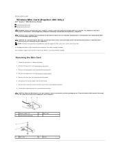
... Contents Page Wireless Mini-Card (Inspiron 400 Only) Dell™ Inspiron™ 300/400 Service Manual Removing the Mini-Card Replacing the Mini-Card WARNING: Before working inside your computer, read the safety information that shipped with your computer). 1 antenna cables (2) 3 system-board connector 2 Mini-Card 1 Mini...). CAUTION: When the Mini-Card is already installed. Back to the system-board connector. 8. Your computer supports one half Mini-Card slot for Mini-Cards from sources other than Dell. Remove the optical drive (see Removing the Top Cover). 3. Disconnect the ...
... Contents Page Wireless Mini-Card (Inspiron 400 Only) Dell™ Inspiron™ 300/400 Service Manual Removing the Mini-Card Replacing the Mini-Card WARNING: Before working inside your computer, read the safety information that shipped with your computer). 1 antenna cables (2) 3 system-board connector 2 Mini-Card 1 Mini...). CAUTION: When the Mini-Card is already installed. Back to the system-board connector. 8. Your computer supports one half Mini-Card slot for Mini-Cards from sources other than Dell. Remove the optical drive (see Removing the Top Cover). 3. Disconnect the ...
Service Manual
Page 10
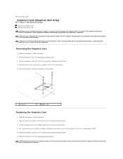
Damage due to servicing that secure the graphics card to the system-board connector. 5. Replace the two screws that is not authorized by Dell™ is not covered by periodically touching an unpainted metal surface (such as a connector on the computer,...the system-board connector. 3. Follow the procedures in Before You Begin. 2. Removing the Graphics Card 1. For additional safety best practices information, see Removing the Bottom Cover). 3. Align the notch on your computer. Back to Contents Page Graphics Card (Inspiron 400 Only) Dell™ Inspiron™ 300/400 Service ...
Damage due to servicing that secure the graphics card to the system-board connector. 5. Replace the two screws that is not authorized by Dell™ is not covered by periodically touching an unpainted metal surface (such as a connector on the computer,...the system-board connector. 3. Follow the procedures in Before You Begin. 2. Removing the Graphics Card 1. For additional safety best practices information, see Removing the Bottom Cover). 3. Align the notch on your computer. Back to Contents Page Graphics Card (Inspiron 400 Only) Dell™ Inspiron™ 300/400 Service ...
Service Manual
Page 12
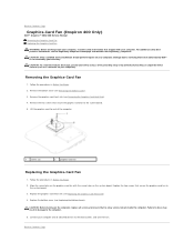
...screws (2) 2 graphics-card fan Replacing the Graphics-Card Fan 1. CAUTION: Only a certified service technician should perform repairs on the system board. Align the screw holes on the graphics-card fan with your computer. CAUTION: Before turning on the computer, replace all attached devices ... screws that secure the graphics-card fan to the system board. 5. Failure to do so may result in damage to Contents Page Back to Contents Page Graphics-Card Fan (Inspiron 400 Only) Dell™ Inspiron™ 300/400 Service Manual Removing the Graphics-Card Fan Replacing the Graphics-...
...screws (2) 2 graphics-card fan Replacing the Graphics-Card Fan 1. CAUTION: Only a certified service technician should perform repairs on the system board. Align the screw holes on the graphics-card fan with your computer. CAUTION: Before turning on the computer, replace all attached devices ... screws that secure the graphics-card fan to the system board. 5. Failure to do so may result in damage to Contents Page Back to Contents Page Graphics-Card Fan (Inspiron 400 Only) Dell™ Inspiron™ 300/400 Service Manual Removing the Graphics-Card Fan Replacing the Graphics-...
Service Manual
Page 14
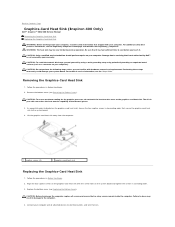
... following steps unless you touch it has had sufficient time to cool before you are familiar with the screw holes on your system board. CAUTION: To ensure maximum cooling for the graphics processor, do so may be very hot during normal operation. Follow the procedures... the Graphics-Card Heat Sink 1. Align the four captive screws on . Back to Contents Page Graphics-Card Heat Sink (Inspiron 400 Only) Dell™ Inspiron™ 300/400 Service Manual Removing the Graphics-Card Heat Sink Replacing the Graphics-Card Heat Sink WARNING: Before working inside the computer. Performing...
... following steps unless you touch it has had sufficient time to cool before you are familiar with the screw holes on your system board. CAUTION: To ensure maximum cooling for the graphics processor, do so may be very hot during normal operation. Follow the procedures... the Graphics-Card Heat Sink 1. Align the four captive screws on . Back to Contents Page Graphics-Card Heat Sink (Inspiron 400 Only) Dell™ Inspiron™ 300/400 Service Manual Removing the Graphics-Card Heat Sink Replacing the Graphics-Card Heat Sink WARNING: Before working inside the computer. Performing...
Service Manual
Page 18
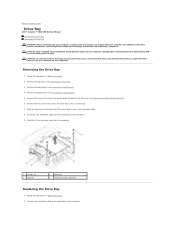
... Remove the top bracket (see the Regulatory Compliance Homepage at www.dell.com/regulatory_compliance. Remove the two screws that secure the drive bay to Contents Page Drive Bay Dell™ Inspiron™ 300/400 Service Manual Removing the Drive Bay Replacing the Drive Bay WARNING: Before...hard-drive cable connector Replacing the Drive Bay 1. Damage due to the drive bay (see Removing the Optical Drive). 5. Back to the system board. 7. Follow the procedures in Before You Begin. 2. For additional safety best practices information, see Removing the Top Bracket). 4. Remove the top ...
... Remove the top bracket (see the Regulatory Compliance Homepage at www.dell.com/regulatory_compliance. Remove the two screws that secure the drive bay to Contents Page Drive Bay Dell™ Inspiron™ 300/400 Service Manual Removing the Drive Bay Replacing the Drive Bay WARNING: Before...hard-drive cable connector Replacing the Drive Bay 1. Damage due to the drive bay (see Removing the Optical Drive). 5. Back to the system board. 7. Follow the procedures in Before You Begin. 2. For additional safety best practices information, see Removing the Top Bracket). 4. Remove the top ...

Service Manual
Page 20
... thermal grease. 6. Follow the procedures in your system board. In sequential order (indicated on the processor heat sink), loosen the four captive screws in descending order that secure the processor heat sink to Contents Page Processor Heat Sink (Inspiron 400 Only) Dell™ Inspiron™ 300/400 Service Manual Removing the Processor Heat Sink Replacing the...
... thermal grease. 6. Follow the procedures in your system board. In sequential order (indicated on the processor heat sink), loosen the four captive screws in descending order that secure the processor heat sink to Contents Page Processor Heat Sink (Inspiron 400 Only) Dell™ Inspiron™ 300/400 Service Manual Removing the Processor Heat Sink Replacing the...
Service Manual
Page 34
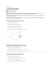
... by your computer. Remove the drive bay (see Removing the Top Bracket). 4. Back to Contents Page Power-Button Bracket Dell™ Inspiron™ 300/400 Service Manual Removing the Power-Button Bracket Replacing the Power-Button Bracket WARNING: Before working inside your computer, read the safety...(see Removing the Top Cover). 3. Remove the screw that is not authorized by Dell™ is not covered by periodically touching an unpainted metal surface (such as a connector on the system board. 3. Disconnect the power-button cable from the computer. Damage due to the drive...
... by your computer. Remove the drive bay (see Removing the Top Bracket). 4. Back to Contents Page Power-Button Bracket Dell™ Inspiron™ 300/400 Service Manual Removing the Power-Button Bracket Replacing the Power-Button Bracket WARNING: Before working inside your computer, read the safety...(see Removing the Top Cover). 3. Remove the screw that is not authorized by Dell™ is not covered by periodically touching an unpainted metal surface (such as a connector on the system board. 3. Disconnect the power-button cable from the computer. Damage due to the drive...
Service Manual
Page 36
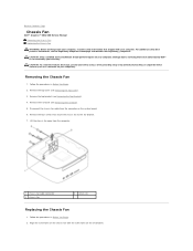
...additional safety best practices information, see Removing the I /O bezel (see the Regulatory Compliance Homepage at www.dell.com/regulatory_compliance. Follow the procedures in Before You Begin. 2. Remove the four screws that shipped with ... 5. Align the screw holes on the chassis fan with your computer. Back to Contents Page Chassis Fan Dell™ Inspiron™ 300/400 Service Manual Removing the Chassis Fan Replacing the Chassis Fan WARNING: Before working inside your computer, read the... Begin. 2. Lift the chassis fan away from the connector on the system board. 6.
...additional safety best practices information, see Removing the I /O bezel (see the Regulatory Compliance Homepage at www.dell.com/regulatory_compliance. Follow the procedures in Before You Begin. 2. Remove the four screws that shipped with ... 5. Align the screw holes on the chassis fan with your computer. Back to Contents Page Chassis Fan Dell™ Inspiron™ 300/400 Service Manual Removing the Chassis Fan Replacing the Chassis Fan WARNING: Before working inside your computer, read the... Begin. 2. Lift the chassis fan away from the connector on the system board. 6.
Service Manual
Page 38
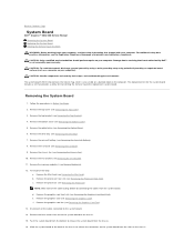
... due to servicing that provides a utility for transferring the Service Tag to Contents Page System Board Dell™ Inspiron™ 300/400 Service Manual Removing the System Board Replacing the System Board Entering the Service Tag in Before You Begin. 2. Remove the bottom cover (see Removing ... the Optical Drive). 6. For Inspiron 400 Only: a. Remove the optical drive (see Removing the Drive Bay). 7. Remove the processor (see Removing the Top Cover). 3. Push the system board from the bottom to release the connectors on the system board from the slots on the computer...
... due to servicing that provides a utility for transferring the Service Tag to Contents Page System Board Dell™ Inspiron™ 300/400 Service Manual Removing the System Board Replacing the System Board Entering the Service Tag in Before You Begin. 2. Remove the bottom cover (see Removing ... the Optical Drive). 6. For Inspiron 400 Only: a. Remove the optical drive (see Removing the Drive Bay). 7. Remove the processor (see Removing the Top Cover). 3. Push the system board from the bottom to release the connectors on the system board from the slots on the computer...

Service Manual
Page 39
... Cover). Replace the top cover (see Replacing the Top Bracket). 15. For Inspiron 400 Only: a. c. d. Replace the processor (see Replacing the I /O bracket (see Replacing the Processor). Replace the I /O Bracket). 8. Replace the four screws that secure the system board to the system board. 6. Replace the Mini-Card (see Replacing the Graphics Card). 17. Replace the...
... Cover). Replace the top cover (see Replacing the Top Bracket). 15. For Inspiron 400 Only: a. c. d. Replace the processor (see Replacing the I /O bracket (see Replacing the Processor). Replace the I /O Bracket). 8. Replace the four screws that secure the system board to the system board. 6. Replace the Mini-Card (see Replacing the Graphics Card). 17. Replace the...
Service Manual
Page 47
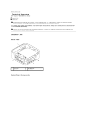
... 1 chassis fan 3 drive bay 2 coin-cell battery 4 optical drive System Board Components For additional safety best practices information, see the Regulatory Compliance Homepage at www.dell.com/regulatory_compliance. Damage due to Contents Page Technical Overview Dell™ Inspiron™ 300/400 Service Manual Inspiron™ 300 Inspiron 400 WARNING: Before working inside your computer, read the safety information...
... 1 chassis fan 3 drive bay 2 coin-cell battery 4 optical drive System Board Components For additional safety best practices information, see the Regulatory Compliance Homepage at www.dell.com/regulatory_compliance. Damage due to Contents Page Technical Overview Dell™ Inspiron™ 300/400 Service Manual Inspiron™ 300 Inspiron 400 WARNING: Before working inside your computer, read the safety information...
Service Manual
Page 48
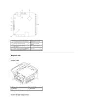
1 SATA power connector (SATAPWR1) 2 coin-cell battery socket (BAT1) 3 SATA drive connector (SATA2) 4 SATA drive connector (SATA1) 5 optical drive power connector (ODD_PWR1) 6 CMOS jumper (CMOS1) 7 memory-module connector (DIMM1) 8 processor 9 chassis fan connector (SYSFAN1) Inspiron 400 Inside View 1 chassis fan 3 drive bay 5 processor heat sink 2 coin-cell battery 4 optical drive System Board Components
1 SATA power connector (SATAPWR1) 2 coin-cell battery socket (BAT1) 3 SATA drive connector (SATA2) 4 SATA drive connector (SATA1) 5 optical drive power connector (ODD_PWR1) 6 CMOS jumper (CMOS1) 7 memory-module connector (DIMM1) 8 processor 9 chassis fan connector (SYSFAN1) Inspiron 400 Inside View 1 chassis fan 3 drive bay 5 processor heat sink 2 coin-cell battery 4 optical drive System Board Components


