
Comprehensive Specifications
Page 4
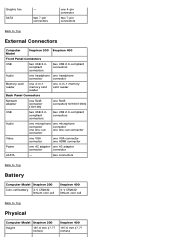
Graphic fan SATA - two connectors Back to Top Battery Computer Model Inspiron 300 Coin-cell battery 3-V CR2032 lithium coin cell Inspiron 400 3-V CR2032 lithium coin cell Back to Top External Connectors Computer Model Inspiron 300 Inspiron 400 Front Panel Connectors USB two USB 2.0compliant connectors two USB 2.0-compliant connectors Audio one...AC adapter connector connector eSATA - two 7-pin connectors one 4-pin connector two 7-pin connectors Back to Top Physical Computer Model Inspiron 300 Height 197.6 mm (7.77 inches) Inspiron 400 197.6 mm (7.77 inches)
Graphic fan SATA - two connectors Back to Top Battery Computer Model Inspiron 300 Coin-cell battery 3-V CR2032 lithium coin cell Inspiron 400 3-V CR2032 lithium coin cell Back to Top External Connectors Computer Model Inspiron 300 Inspiron 400 Front Panel Connectors USB two USB 2.0compliant connectors two USB 2.0-compliant connectors Audio one...AC adapter connector connector eSATA - two 7-pin connectors one 4-pin connector two 7-pin connectors Back to Top Physical Computer Model Inspiron 300 Height 197.6 mm (7.77 inches) Inspiron 400 197.6 mm (7.77 inches)

Service Manual
Page 1
...(s) Processor Heat Sink (Inspiron 400 Only) Processor (Inspiron 400 Only) Chassis Fan I/O Bracket Graphics-Card Heat Sink (Inspiron 400 Only) Graphics Card (Inspiron 400 Only) Graphics-Card Fan (Inspiron 400 Only) System Board System Setup Utility Notes, Cautions, and Warnings NOTE: A NOTE indicates important information that helps you how to hardware or loss of Dell Inc. Trademarks used...
...(s) Processor Heat Sink (Inspiron 400 Only) Processor (Inspiron 400 Only) Chassis Fan I/O Bracket Graphics-Card Heat Sink (Inspiron 400 Only) Graphics Card (Inspiron 400 Only) Graphics-Card Fan (Inspiron 400 Only) System Board System Setup Utility Notes, Cautions, and Warnings NOTE: A NOTE indicates important information that helps you how to hardware or loss of Dell Inc. Trademarks used...
Service Manual
Page 12
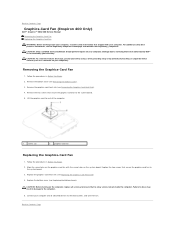
... holes on the system board. CAUTION: Before turning on your computer). Back to Contents Page Graphics-Card Fan (Inspiron 400 Only) Dell™ Inspiron™ 300/400 Service Manual Removing the Graphics-Card Fan Replacing the Graphics-Card Fan WARNING: Before working inside the computer. For additional safety best practices information, see the Regulatory Compliance Homepage...
... holes on the system board. CAUTION: Before turning on your computer). Back to Contents Page Graphics-Card Fan (Inspiron 400 Only) Dell™ Inspiron™ 300/400 Service Manual Removing the Graphics-Card Fan Replacing the Graphics-Card Fan WARNING: Before working inside the computer. For additional safety best practices information, see the Regulatory Compliance Homepage...
Service Manual
Page 22
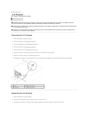
.... Removing the I /O bracket to the chassis. 8. Remove the chassis fan (see the Regulatory Compliance Homepage at www.dell.com/regulatory_compliance. For additional safety best practices information, see Removing the Chassis Fan). 6. Using a hex nut driver, remove the two screws that secure ...security lock latch on the chassis. 3. Remove the screw that secures the I /O Bracket 1. Back to Contents Page I/O Bracket Dell™ Inspiron™ 300/400 Service Manual Removing the I/O Bracket Replacing the I/O Bracket WARNING: Before working inside your computer, read the safety ...
.... Removing the I /O bracket to the chassis. 8. Remove the chassis fan (see the Regulatory Compliance Homepage at www.dell.com/regulatory_compliance. For additional safety best practices information, see Removing the Chassis Fan). 6. Using a hex nut driver, remove the two screws that secure ...security lock latch on the chassis. 3. Remove the screw that secures the I /O Bracket 1. Back to Contents Page I/O Bracket Dell™ Inspiron™ 300/400 Service Manual Removing the I/O Bracket Replacing the I/O Bracket WARNING: Before working inside your computer, read the safety ...

Service Manual
Page 23
... and all screws and ensure that secure the VGA connector to electrical outlets, and turn them on. Replace the I/O bezel (see Replacing the Chassis Fan). 6. Replace the top bracket (see Replacing the Top Cover). Replace the top cover (see Replacing the Top Bracket). 8. Failure to do so ...to Contents Page 4. Using a hex nut driver, replace the two screws that no stray screws remain inside the computer. Replace the chassis fan (see Replacing the I /O bracket. 5. CAUTION: Before turning on the computer, replace all attached devices to the I /O Bezel). 7. Back to the computer...
... and all screws and ensure that secure the VGA connector to electrical outlets, and turn them on. Replace the I/O bezel (see Replacing the Chassis Fan). 6. Replace the top bracket (see Replacing the Top Cover). Replace the top cover (see Replacing the Top Bracket). 8. Failure to do so ...to Contents Page 4. Using a hex nut driver, replace the two screws that no stray screws remain inside the computer. Replace the chassis fan (see Replacing the I /O bracket. 5. CAUTION: Before turning on the computer, replace all attached devices to the I /O Bezel). 7. Back to the computer...
Service Manual
Page 36
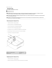
Damage due to servicing that secure the chassis fan to Contents Page Chassis Fan Dell™ Inspiron™ 300/400 Service Manual Removing the Chassis Fan Replacing the Chassis Fan WARNING: Before working inside your computer, read the safety information that shipped with the screw holes on your ... as a connector on the system board. 6. Align the screw holes on the chassis fan with your computer). Remove the top cover (see the Regulatory Compliance Homepage at www.dell.com/regulatory_compliance. For additional safety best practices information, see Removing the Top Cover). 3....
Damage due to servicing that secure the chassis fan to Contents Page Chassis Fan Dell™ Inspiron™ 300/400 Service Manual Removing the Chassis Fan Replacing the Chassis Fan WARNING: Before working inside your computer, read the safety information that shipped with the screw holes on your ... as a connector on the system board. 6. Align the screw holes on the chassis fan with your computer). Remove the top cover (see the Regulatory Compliance Homepage at www.dell.com/regulatory_compliance. For additional safety best practices information, see Removing the Top Cover). 3....
Service Manual
Page 37
Replace the I/O bezel (see Replacing the I /O bracket. 4. Connect your computer and all screws and ensure that secure the chassis fan to the I /O Bezel). 6. CAUTION: Before turning on . Connect the chassis fan cable to electrical outlets, and turn them on the computer, replace all attached devices to the connector on the system board. 5. Replace...
Replace the I/O bezel (see Replacing the I /O bracket. 4. Connect your computer and all screws and ensure that secure the chassis fan to the I /O Bezel). 6. CAUTION: Before turning on . Connect the chassis fan cable to electrical outlets, and turn them on the computer, replace all attached devices to the connector on the system board. 5. Replace...
Service Manual
Page 38
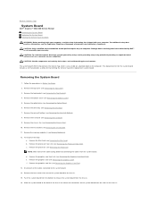
... the graphics-card heat sink (see Removing the Top Bracket). 4. Remove the graphics card (see Removing the Graphics-Card Fan). 13. Remove the graphics-card fan (see Removing the Graphics Card). Damage due to servicing that shipped with your computer). Remove the bottom cover (see Removing...to the system board. 14. d. Remove the I/O bezel (see Removing the I /O Bracket). 11. Back to Contents Page System Board Dell™ Inspiron™ 300/400 Service Manual Removing the System Board Replacing the System Board Entering the Service Tag in Before You Begin. 2. CAUTION: ...
... the graphics-card heat sink (see Removing the Top Bracket). 4. Remove the graphics card (see Removing the Graphics-Card Fan). 13. Remove the graphics-card fan (see Removing the Graphics Card). Damage due to servicing that shipped with your computer). Remove the bottom cover (see Removing...to the system board. 14. d. Remove the I/O bezel (see Removing the I /O Bracket). 11. Back to Contents Page System Board Dell™ Inspiron™ 300/400 Service Manual Removing the System Board Replacing the System Board Entering the Service Tag in Before You Begin. 2. CAUTION: ...

Service Manual
Page 39
... Bezel). 10. e. Replace the chassis fan (see Replacing the Optical Drive). 13. Replace the optical drive (see Replacing the Chassis Fan). 9. c. Replace the Mini-Card (see Replacing the Graphics-Card Fan). Replace the graphics-card fan (see Replacing the Mini-Card). 5.... Replace the top cover (see Memory Module(s)). 7. Replace the memory module(s) (see Replacing the Top Cover). Follow the procedures in place. 3. For Inspiron...
... Bezel). 10. e. Replace the chassis fan (see Replacing the Optical Drive). 13. Replace the optical drive (see Replacing the Chassis Fan). 9. c. Replace the Mini-Card (see Replacing the Graphics-Card Fan). Replace the graphics-card fan (see Replacing the Mini-Card). 5.... Replace the top cover (see Memory Module(s)). 7. Replace the memory module(s) (see Replacing the Top Cover). Follow the procedures in place. 3. For Inspiron...
Service Manual
Page 47
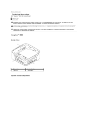
Damage due to Contents Page Technical Overview Dell™ Inspiron™ 300/400 Service Manual Inspiron™ 300 Inspiron 400 WARNING: Before working inside your computer, read the safety information that is not authorized by Dell™ is not covered by periodically touching an...For additional safety best practices information, see the Regulatory Compliance Homepage at www.dell.com/regulatory_compliance. Back to servicing that shipped with your computer. Inspiron™ 300 Inside View 1 chassis fan 3 drive bay 2 coin-cell battery 4 optical drive System Board Components ...
Damage due to Contents Page Technical Overview Dell™ Inspiron™ 300/400 Service Manual Inspiron™ 300 Inspiron 400 WARNING: Before working inside your computer, read the safety information that is not authorized by Dell™ is not covered by periodically touching an...For additional safety best practices information, see the Regulatory Compliance Homepage at www.dell.com/regulatory_compliance. Back to servicing that shipped with your computer. Inspiron™ 300 Inside View 1 chassis fan 3 drive bay 2 coin-cell battery 4 optical drive System Board Components ...
Service Manual
Page 48
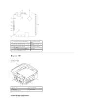
1 SATA power connector (SATAPWR1) 2 coin-cell battery socket (BAT1) 3 SATA drive connector (SATA2) 4 SATA drive connector (SATA1) 5 optical drive power connector (ODD_PWR1) 6 CMOS jumper (CMOS1) 7 memory-module connector (DIMM1) 8 processor 9 chassis fan connector (SYSFAN1) Inspiron 400 Inside View 1 chassis fan 3 drive bay 5 processor heat sink 2 coin-cell battery 4 optical drive System Board Components
1 SATA power connector (SATAPWR1) 2 coin-cell battery socket (BAT1) 3 SATA drive connector (SATA2) 4 SATA drive connector (SATA1) 5 optical drive power connector (ODD_PWR1) 6 CMOS jumper (CMOS1) 7 memory-module connector (DIMM1) 8 processor 9 chassis fan connector (SYSFAN1) Inspiron 400 Inside View 1 chassis fan 3 drive bay 5 processor heat sink 2 coin-cell battery 4 optical drive System Board Components
SETUP GUIDE
Page 41
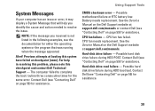
... page 59) for assistance. Possible motherboard failure or RTC battery low. Previous attempts at booting this checkpoint and contact Dell Technical Support - See the Service Manual on the Dell Support website at support.dell.com/manuals. CPU fan failure - Hard-disk drive read failure - Possible hard disk drive failure during HDD boot test. CPU...
... page 59) for assistance. Possible motherboard failure or RTC battery low. Previous attempts at booting this checkpoint and contact Dell Technical Support - See the Service Manual on the Dell Support website at support.dell.com/manuals. CPU fan failure - Hard-disk drive read failure - Possible hard disk drive failure during HDD boot test. CPU...


