
Setup Guide
Page 6
... Problems 59 Memory Problems 61 Lockups and Software Problems 61 Using Support Tools 64 Dell Support Center 64 My Dell Downloads 65 Hardware Troubleshooter 66 Dell Diagnostics 66 Restoring Your Operating System 68 System Restore 69 Dell DataSafe Local Backup 70 System Recovery Media 73 Dell Factory Image ...Status Service 79 Product Information 79 Returning Items for Repair Under Warranty or for Credit 80 Before You Call 82 Contacting Dell 84 Finding More Information and Resources 86 Specifications 88 Appendix 95 Information for NOM, or Official Mexican Standard (Only for Mexico...
... Problems 59 Memory Problems 61 Lockups and Software Problems 61 Using Support Tools 64 Dell Support Center 64 My Dell Downloads 65 Hardware Troubleshooter 66 Dell Diagnostics 66 Restoring Your Operating System 68 System Restore 69 Dell DataSafe Local Backup 70 System Recovery Media 73 Dell Factory Image ...Status Service 79 Product Information 79 Returning Items for Repair Under Warranty or for Credit 80 Before You Call 82 Contacting Dell 84 Finding More Information and Resources 86 Specifications 88 Appendix 95 Information for NOM, or Official Mexican Standard (Only for Mexico...

Setup Guide
Page 27
NOTE: Your computer ships with a plastic blank installed in -1 Media Card Reader - Blanks protect unused slots from other particles. Using Your Inspiron Laptop 4 8-in the media card slot. blanks from dust and other computers may not fit your computer. 25 Provides a fast and convenient way to view and share digital photos, music, videos, and documents stored on page 88. For the supported memory cards, see "Specifications" on memory cards. Save the blank for use when no media card is installed in the slot;
NOTE: Your computer ships with a plastic blank installed in -1 Media Card Reader - Blanks protect unused slots from other particles. Using Your Inspiron Laptop 4 8-in the media card slot. blanks from dust and other computers may not fit your computer. 25 Provides a fast and convenient way to view and share digital photos, music, videos, and documents stored on page 88. For the supported memory cards, see "Specifications" on memory cards. Save the blank for use when no media card is installed in the slot;

Setup Guide
Page 58
... of beeps, called a beep code, identifies a problem. INSPIRON Solving Problems This section provides troubleshooting information for advanced service instructions. If this occurs, write down the beep code and contact Dell (see "Using Support Tools" on page 64 or "Contacting Dell" on page 84) for assistance. Chipset error RAM read/...Code One Two Three Four Five Six Seven Eight 56 Possible Problem Possible system board failure - See the Service Manual at support.dell.com. If you installed or replaced the memory module, ensure that the memory module is seated properly.
... of beeps, called a beep code, identifies a problem. INSPIRON Solving Problems This section provides troubleshooting information for advanced service instructions. If this occurs, write down the beep code and contact Dell (see "Using Support Tools" on page 64 or "Contacting Dell" on page 84) for assistance. Chipset error RAM read/...Code One Two Three Four Five Six Seven Eight 56 Possible Problem Possible system board failure - See the Service Manual at support.dell.com. If you installed or replaced the memory module, ensure that the memory module is seated properly.

Setup Guide
Page 63
.../manuals). • If the problem persists, contact Dell (see "Contacting Dell" on the CD. 61 Solving Problems Memory Problems If you receive an insufficient memory message - • Save and close any open files and exit any open programs you experience other memory problems - • Run Dell Diagnostics (see "Dell Diagnostics" on page 66). • If the problem...
.../manuals). • If the problem persists, contact Dell (see "Contacting Dell" on the CD. 61 Solving Problems Memory Problems If you receive an insufficient memory message - • Save and close any open files and exit any open programs you experience other memory problems - • Run Dell Diagnostics (see "Dell Diagnostics" on page 66). • If the problem...

Setup Guide
Page 66
INSPIRON Using Support Tools Dell Support Center All the support you need - The...track the changes made to access: PC Checkup - PC Checkup Utilities • Drive Space Manager - The Dell Support Center home page displays your computer's model number, service tag, express service code, warranty status, and...keyboard or click Start → All Programs→ Dell→ Dell Support Center→ Launch Dell Support Center. one convenient location. Run hardware diagnostics, see which program occupies the maximum memory on improving the performance of file. • Performance...
INSPIRON Using Support Tools Dell Support Center All the support you need - The...track the changes made to access: PC Checkup - PC Checkup Utilities • Drive Space Manager - The Dell Support Center home page displays your computer's model number, service tag, express service code, warranty status, and...keyboard or click Start → All Programs→ Dell→ Dell Support Center→ Launch Dell Support Center. one convenient location. Run hardware diagnostics, see which program occupies the maximum memory on improving the performance of file. • Performance...

Setup Guide
Page 68
...Troubleshooter to resolve the incompatibility. Turn on (or restart) your computer and press when the Dell logo appears. Dell Diagnostics If you experience a problem with your computer. 2. When the DELL logo appears, press immediately. 66 Type hardware troubleshooter in "Lockups and Software Problems" on ...start the Hardware Troubleshooter: 1. Ensure that best describes the problem and follow the remaining troubleshooting steps. Starting Dell Diagnostics When you contact Dell for devices such as the system board, keyboard, display, memory, hard drive, and so on. 1.
...Troubleshooter to resolve the incompatibility. Turn on (or restart) your computer and press when the Dell logo appears. Dell Diagnostics If you experience a problem with your computer. 2. When the DELL logo appears, press immediately. 66 Type hardware troubleshooter in "Lockups and Software Problems" on ...start the Hardware Troubleshooter: 1. Ensure that best describes the problem and follow the remaining troubleshooting steps. Starting Dell Diagnostics When you contact Dell for devices such as the system board, keyboard, display, memory, hard drive, and so on. 1.

Setup Guide
Page 69
During the assessment, answer any questions that failed, press . • If failures are experiencing memory issues, press , otherwise press . Click to the next test, press ; Do you want to continue? (Recommended)." The following message appears "Do you want to...Select Diagnostics from the boot menu and press . to continue to reboot your computer and try again. 3. If you see "Contacting Dell" on page 84). to run the remaining memory tests? This will take about 30 minutes or more information, see the Microsoft Windows desktop; then, shut down the error code(s) and...
During the assessment, answer any questions that failed, press . • If failures are experiencing memory issues, press , otherwise press . Click to the next test, press ; Do you want to continue? (Recommended)." The following message appears "Do you want to...Select Diagnostics from the boot menu and press . to continue to reboot your computer and try again. 3. If you see "Contacting Dell" on page 84). to run the remaining memory tests? This will take about 30 minutes or more information, see the Microsoft Windows desktop; then, shut down the error code(s) and...

Setup Guide
Page 90
... need when setting up, updating drivers for, and upgrading your computer, see the Detailed System Information section in the Dell Support Center. Computer Model Memory Dell Inspiron N5110 Computer Information System chipset Mobile Intel 6 Series Memory module connector Memory module capacities two user-accessible SODIMM connectors 1 GB, 2 GB, and 4 GB Processor types Intel Core i3 Intel Core...
... need when setting up, updating drivers for, and upgrading your computer, see the Detailed System Information section in the Dell Support Center. Computer Model Memory Dell Inspiron N5110 Computer Information System chipset Mobile Intel 6 Series Memory module connector Memory module capacities two user-accessible SODIMM connectors 1 GB, 2 GB, and 4 GB Processor types Intel Core i3 Intel Core...

Setup Guide
Page 91
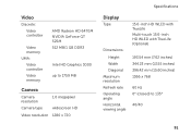
... USB 2.0-compliant connector two 4-pin USB 3.0-compliant connectors one 15-hole connector one 7-pin/4-pin eSATA/ USB combo connector with PowerShare one 8-in-1 slot 89 Memory Possible memory 2 GB, 3 GB, 4 GB, 6 GB, configurations and 8 GB Memory type 1333 MHz SODIMM DDR3 NOTE: For instructions on upgrading the...
... USB 2.0-compliant connector two 4-pin USB 3.0-compliant connectors one 15-hole connector one 7-pin/4-pin eSATA/ USB combo connector with PowerShare one 8-in-1 slot 89 Memory Possible memory 2 GB, 3 GB, 4 GB, 6 GB, configurations and 8 GB Memory type 1333 MHz SODIMM DDR3 NOTE: For instructions on upgrading the...

Setup Guide
Page 92
... 2 x 2 Watt Volume controls software program menus and media controls Specifications Media Card Reader Cards supported Secure Digital (SD) memory card Secure Digital Extended Capacity (SDXC) Secure Digital High Capacity (SDHC) Memory Stick (MS) Memory Stick PRO (MS-PRO) MultiMedia Card (MMC) MultiMedia Card plus (MMC+) xD-Picture Card Keyboard Number of keys 86...
... 2 x 2 Watt Volume controls software program menus and media controls Specifications Media Card Reader Cards supported Secure Digital (SD) memory card Secure Digital Extended Capacity (SDXC) Secure Digital High Capacity (SDHC) Memory Stick (MS) Memory Stick PRO (MS-PRO) MultiMedia Card (MMC) MultiMedia Card plus (MMC+) xD-Picture Card Keyboard Number of keys 86...
Setup Guide
Page 93
Video Discrete: Video controller Video memory UMA: Video controller Video memory AMD Radeon HD 6470M NVIDIA GeForce GT 525M 512 MB/1 GB DDR3 Intel HD Graphics 3000 up to 1759 MB Camera Camera resolution Camera type 1.0 ...
Video Discrete: Video controller Video memory UMA: Video controller Video memory AMD Radeon HD 6470M NVIDIA GeForce GT 525M 512 MB/1 GB DDR3 Intel HD Graphics 3000 up to 1759 MB Camera Camera resolution Camera type 1.0 ...
Setup Guide
Page 99
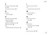
F finding more information 86 flick 44 FTP login, anonymous 78 G gestures Touch Pad 36 H hard drive activity light 29 hardware problems diagnosing 66 Hardware Troubleshooter 66 HDMI connector 23 help getting assistance and support 76 I Internet connection 17 ISP Internet Service Provider 17 M memory problems solving 61 N network connection fixing 58 O Optical Drive emergency eject hole 40 Using 40 P power indicator light 29 Index 97
F finding more information 86 flick 44 FTP login, anonymous 78 G gestures Touch Pad 36 H hard drive activity light 29 hardware problems diagnosing 66 Hardware Troubleshooter 66 HDMI connector 23 help getting assistance and support 76 I Internet connection 17 ISP Internet Service Provider 17 M memory problems solving 61 N network connection fixing 58 O Optical Drive emergency eject hole 40 Using 40 P power indicator light 29 Index 97
Service Manual
Page 3
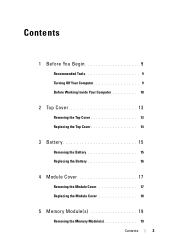
Contents 1 Before You Begin 9 Recommended Tools 9 Turning Off Your Computer 9 Before Working Inside Your Computer 10 2 Top Cover 13 Removing the Top Cover 13 Replacing the Top Cover 14 3 Battery 15 Removing the Battery 15 Replacing the Battery 16 4 Module Cover 17 Removing the Module Cover 17 Replacing the Module Cover 18 5 Memory Module(s 19 Removing the Memory Module(s 19 Contents 3
Contents 1 Before You Begin 9 Recommended Tools 9 Turning Off Your Computer 9 Before Working Inside Your Computer 10 2 Top Cover 13 Removing the Top Cover 13 Replacing the Top Cover 14 3 Battery 15 Removing the Battery 15 Replacing the Battery 16 4 Module Cover 17 Removing the Module Cover 17 Replacing the Module Cover 18 5 Memory Module(s 19 Removing the Memory Module(s 19 Contents 3

Service Manual
Page 4
Replacing the Memory Module(s 20 6 Optical Drive 23 Removing the Optical Drive 23 Replacing the Optical Drive 24 7 Keyboard 27 Removing the Keyboard 27 Replacing the Keyboard 29 8 Palm-Rest Assembly 31 Removing the Palm-Rest Assembly 31 Replacing the Palm-Rest Assembly 34 9 Wireless Mini-Card(s 37 Removing the Mini-Card(s 37 Replacing the Mini-Card(s 39 10 Display 41 Display Assembly 41 Removing the Display Assembly 41 Replacing the Display Assembly 43 Display Bezel 44 4 Contents
Replacing the Memory Module(s 20 6 Optical Drive 23 Removing the Optical Drive 23 Replacing the Optical Drive 24 7 Keyboard 27 Removing the Keyboard 27 Replacing the Keyboard 29 8 Palm-Rest Assembly 31 Removing the Palm-Rest Assembly 31 Replacing the Palm-Rest Assembly 34 9 Wireless Mini-Card(s 37 Removing the Mini-Card(s 37 Replacing the Mini-Card(s 39 10 Display 41 Display Assembly 41 Removing the Display Assembly 41 Replacing the Display Assembly 43 Display Bezel 44 4 Contents

Service Manual
Page 19
... the instructions in your Setup Guide for information on the type of memory supported by installing memory modules on page 15). 3 Remove the module cover (see the Regulatory Compliance Homepage at dell.com/regulatory_compliance. For additional safety best practices information, see "Removing the... certified service technician should perform repairs on your computer memory by your computer. You can be accessed from the bottom of the memory-module connector until the memory module pops up. 5 Remove the memory module from Dell are covered under your fingertips to the system board...
... the instructions in your Setup Guide for information on the type of memory supported by installing memory modules on page 15). 3 Remove the module cover (see the Regulatory Compliance Homepage at dell.com/regulatory_compliance. For additional safety best practices information, see "Removing the... certified service technician should perform repairs on your computer memory by your computer. You can be accessed from the bottom of the memory-module connector until the memory module pops up. 5 Remove the memory module from Dell are covered under your fingertips to the system board...
Service Manual
Page 20
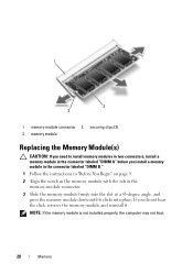
... firmly into the slot at a 45-degree angle, and press the memory module down until it . NOTE: If the memory module is not installed properly, the computer may not boot. 20 Memory If you install a memory module in the connector labeled "DIMM B." 1 Follow the instructions in "Before You Begin" on page 9. 2 Align the notch...
... firmly into the slot at a 45-degree angle, and press the memory module down until it . NOTE: If the memory module is not installed properly, the computer may not boot. 20 Memory If you install a memory module in the connector labeled "DIMM B." 1 Follow the instructions in "Before You Begin" on page 9. 2 Align the notch...
Service Manual
Page 21
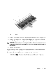
... screws and ensure that no stray screws remain inside the computer. As the computer boots, it detects the memory module(s) and automatically updates the system configuration information. Memory 21 To confirm the amount of memory installed in damage to the computer. 6 Turn on the computer. Failure to your computer and an electrical outlet...
... screws and ensure that no stray screws remain inside the computer. As the computer boots, it detects the memory module(s) and automatically updates the system configuration information. Memory 21 To confirm the amount of memory installed in damage to the computer. 6 Turn on the computer. Failure to your computer and an electrical outlet...

Service Manual
Page 65
... shipped with your computer. 14 System Board WARNING: Before working inside your computer, read the safety information that is not authorized by Dell is not covered by their edges, and avoid touching pins and contacts. CAUTION: Only a certified service technician should perform repairs on...page 17). 5 Follow the instructions from step 4 to step 5 in "Removing the Optical Drive" on page 23. 6 Remove the memory module(s) (see "Removing the Memory Module(s)" on page 19). 7 Follow the instructions from step 3 to the system board, remove the main battery (see "Removing the Battery...
... shipped with your computer. 14 System Board WARNING: Before working inside your computer, read the safety information that is not authorized by Dell is not covered by their edges, and avoid touching pins and contacts. CAUTION: Only a certified service technician should perform repairs on...page 17). 5 Follow the instructions from step 4 to step 5 in "Removing the Optical Drive" on page 23. 6 Remove the memory module(s) (see "Removing the Memory Module(s)" on page 19). 7 Follow the instructions from step 3 to the system board, remove the main battery (see "Removing the Battery...
Service Manual
Page 67
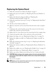
Failure to do so may result in damage to step 7 in "Replacing the Palm-Rest Assembly" on page 34. 13 Replace the memory module (see "Replacing the Memory Module(s)" on page 20). 14 Replace the module cover (see "Replacing the Module Cover" on page 18). 15 Replace the battery (see "Replacing the Battery...
Failure to do so may result in damage to step 7 in "Replacing the Palm-Rest Assembly" on page 34. 13 Replace the memory module (see "Replacing the Memory Module(s)" on page 20). 14 Replace the module cover (see "Replacing the Module Cover" on page 18). 15 Replace the battery (see "Replacing the Battery...


