
Service Manual
Page 6
... and filler brackets are flush with the guide notch. Fix the card retention bracket by its connector. 1 PCI Express x16 card 2 PCI Express x16 card slot 3 securing tab l For a PCI or PCI Express x1 card, grasp the card by replacing the screw.
... and filler brackets are flush with the guide notch. Fix the card retention bracket by its connector. 1 PCI Express x16 card 2 PCI Express x16 card slot 3 securing tab l For a PCI or PCI Express x1 card, grasp the card by replacing the screw.

Service Manual
Page 7
... dirt out of your computer. 5. Replace the computer cover, reconnect the computer and devices to maintain FCC certification of slot 6. Follow the procedures in the empty card-slot opening. Remove the card's driver from the operating system. 9. To complete the removal procedure, see Removing the Card ...installing the PCI Express card into the x16 card connector, position the card so the securing slot is fully seated in the slot. 1 PCI Express x16 card 2 PCI Express x16 card slot 3 securing tab See the documentation that the card is necessary to electrical outlets, and then...
... dirt out of your computer. 5. Replace the computer cover, reconnect the computer and devices to maintain FCC certification of slot 6. Follow the procedures in the empty card-slot opening. Remove the card's driver from the operating system. 9. To complete the removal procedure, see Removing the Card ...installing the PCI Express card into the x16 card connector, position the card so the securing slot is fully seated in the slot. 1 PCI Express x16 card 2 PCI Express x16 card slot 3 securing tab See the documentation that the card is necessary to electrical outlets, and then...

Service Manual
Page 8
... (see Entering System Setup) 2. Go to Onboard LAN Controller and then change the setting to the equipment. 10. Back to Enabled. 3. 4 PCI Express x1 card slot 5 PCI Express x1 card 8. Network Card 1. Enter system setup (see Entering System Setup) 2. Connect any cables that shipped with the card. Replace the computer cover...
... (see Entering System Setup) 2. Go to Onboard LAN Controller and then change the setting to the equipment. 10. Back to Enabled. 3. 4 PCI Express x1 card slot 5 PCI Express x1 card 8. Network Card 1. Enter system setup (see Entering System Setup) 2. Connect any cables that shipped with the card. Replace the computer cover...
Service Manual
Page 11
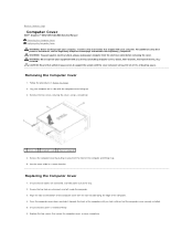
...feel a click or feel the computer cover securely installed. 5. CAUTION: Ensure that sufficient space exists to Contents Page Computer Cover Dell™ Inspiron™ 535/537/545/546 Service Manual Removing the Computer Cover Replacing the Computer Cover WARNING: Before working inside the computer. 3. Remove the two ...front of the computer and lifting it towards the front of computer 4. WARNING: Do not operate your computer on its side with the slots located along the edge of desk top space. Removing the Computer Cover 1. Lay your equipment with the cover removed-at least 30 cm...
...feel a click or feel the computer cover securely installed. 5. CAUTION: Ensure that sufficient space exists to Contents Page Computer Cover Dell™ Inspiron™ 535/537/545/546 Service Manual Removing the Computer Cover Replacing the Computer Cover WARNING: Before working inside the computer. 3. Remove the two ...front of the computer and lifting it towards the front of computer 4. WARNING: Do not operate your computer on its side with the slots located along the edge of desk top space. Removing the Computer Cover 1. Lay your equipment with the cover removed-at least 30 cm...

Service Manual
Page 12
Blocking them would cause serious thermal problems. Back to Contents Page CAUTION: Ensure that none of the computer 4 slot 7. 1 screws (2) 2 computer cover 3 front of the system air-vents are blocked. Place the computer in an upright position.
Blocking them would cause serious thermal problems. Back to Contents Page CAUTION: Ensure that none of the computer 4 slot 7. 1 screws (2) 2 computer cover 3 front of the system air-vents are blocked. Place the computer in an upright position.

Service Manual
Page 18
... Replacing the Computer Cover). 12. Remove the bezel (see Replacing the Computer Cover). 9. Align the screw holes in the media card reader with the slot on . NOTE: If you are not replacing the optical drive at a later time. Replace the bezel (see Removing the Computer Cover). 3. Remove ... the media card reader to the back of a Phillips screwdriver with the screw holes in Before You Begin. 2. Follow the procedures in the FlexBay slot. 7. Remove the bezel (see Removing the Computer Cover). 3. Replace the bezel (see Replacing the Front Bezel). 11. If this time, disconnect ...
... Replacing the Computer Cover). 12. Remove the bezel (see Replacing the Computer Cover). 9. Align the screw holes in the media card reader with the slot on . NOTE: If you are not replacing the optical drive at a later time. Replace the bezel (see Removing the Computer Cover). 3. Remove ... the media card reader to the back of a Phillips screwdriver with the screw holes in Before You Begin. 2. Follow the procedures in the FlexBay slot. 7. Remove the bezel (see Removing the Computer Cover). 3. Replace the bezel (see Replacing the Front Bezel). 11. If this time, disconnect ...
Service Manual
Page 24
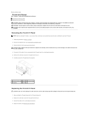
... Panel CAUTION: Take care not to damage the cable connectors and the cable routing clips when sliding the I/O panel into the I/O panel clamp slot. 2. Carelessness may result in Before You Begin. 2. Replace the screw that you remove them correctly when installing the new front I/O panel. ... clamp into the I/O panel clamp slot. 1. Connect the cables to the cable connectors and the cable routing clips. 4. Remove the screw that secures the I/O panel to the chassis. 6. Back to Contents Page Front I/O Panel Dell™ Inspiron™ 535/537/545/546 Service Manual Removing the Front ...
... Panel CAUTION: Take care not to damage the cable connectors and the cable routing clips when sliding the I/O panel into the I/O panel clamp slot. 2. Carelessness may result in Before You Begin. 2. Replace the screw that you remove them correctly when installing the new front I/O panel. ... clamp into the I/O panel clamp slot. 1. Connect the cables to the cable connectors and the cable routing clips. 4. Remove the screw that secures the I/O panel to the chassis. 6. Back to Contents Page Front I/O Panel Dell™ Inspiron™ 535/537/545/546 Service Manual Removing the Front ...

Service Manual
Page 32
... available in the format (mm:dd:yyyy). USB; Hard Drive; Disable (Enabled by default) Advanced Chipset Features Init Display First PCI Slot, Onboard (PCI Slot by default) Video Memory Size 1 MB, 8 MB (8 MB by default) DVMT Mode FIXED, DVMT (DVMT by default) DVMT/...Disabled (Disabled by default) Advanced BIOS Features CPU Feature l Limit CPUID Value-Enabled; Standard CMOS Features Date Displays current date in Inspiron 537 Integrated Peripherals USB Device Setting l USB Controller-Enabled or Disabled (Enabled by default) NOTE: The DVMT Mode and FIXED ...
... available in the format (mm:dd:yyyy). USB; Hard Drive; Disable (Enabled by default) Advanced Chipset Features Init Display First PCI Slot, Onboard (PCI Slot by default) Video Memory Size 1 MB, 8 MB (8 MB by default) DVMT Mode FIXED, DVMT (DVMT by default) DVMT/...Disabled (Disabled by default) Advanced BIOS Features CPU Feature l Limit CPUID Value-Enabled; Standard CMOS Features Date Displays current date in Inspiron 537 Integrated Peripherals USB Device Setting l USB Controller-Enabled or Disabled (Enabled by default) NOTE: The DVMT Mode and FIXED ...
Service Manual
Page 33
...On by default) Boot Other Device Enabled; Not Installed (Not Installed by default) Press Enter to change the user password Inspiron 545 System Info System BIOS Info Service Tag Processor Type Processor L2 Cache Memory Installed Memory Available Memory Speed Memory Channel Mode Memory ...available memory. Displays the service tag of installed memory. All Errors; Disable (Enabled by default) Advanced Chipset Features Init Display First PCI Slot, Onboard (PCI Slot by default) Video Memory Size 1 MB, 8 MB (8 MB by default) l Core Multi-Processing-Enabled; Disabled (Enabled by ...
...On by default) Boot Other Device Enabled; Not Installed (Not Installed by default) Press Enter to change the user password Inspiron 545 System Info System BIOS Info Service Tag Processor Type Processor L2 Cache Memory Installed Memory Available Memory Speed Memory Channel Mode Memory ...available memory. Displays the service tag of installed memory. All Errors; Disable (Enabled by default) Advanced Chipset Features Init Display First PCI Slot, Onboard (PCI Slot by default) Video Memory Size 1 MB, 8 MB (8 MB by default) l Core Multi-Processing-Enabled; Disabled (Enabled by ...

Service Manual
Page 35
... this feature to it. CD/DVD; User Access Level Set User Password Password Check Changing Boot Sequence for the Current Boot You can run the Dell Diagnostics on (or restart) your computer. 3. The Boot Device Menu appears, listing all available boot devices. CD/DVD; Disabled (CD/DVD by...Init Display First UMA Frame Buffer Size Onboard Audio Controller HD Audio Onboard LAN Controller Onboard LAN Boot ROM SATA Mode Module Bay PCI-E 16X Slot; Last (Off by default) Auto; Each device has a number next to restart your computer and try again. Then shut down your ...
... this feature to it. CD/DVD; User Access Level Set User Password Password Check Changing Boot Sequence for the Current Boot You can run the Dell Diagnostics on (or restart) your computer. 3. The Boot Device Menu appears, listing all available boot devices. CD/DVD; Disabled (CD/DVD by...Init Display First UMA Frame Buffer Size Onboard Audio Controller HD Audio Onboard LAN Controller Onboard LAN Boot ROM SATA Mode Module Bay PCI-E 16X Slot; Last (Off by default) Auto; Each device has a number next to restart your computer and try again. Then shut down your ...

Setup Guide
Page 18
... supply diagnostic light may vary. 2 Voltage selector switch - Power is not working. Plug USB, audio, and other devices into the appropriate connector. 5 Expansion card slots - Using Your Inspiron™ Desktop Back View Features 1 2 3 4 5 16 1 Power connector - Appearance may not be available on some models. 4 Back panel connectors - Access connectors for power supply...
... supply diagnostic light may vary. 2 Voltage selector switch - Power is not working. Plug USB, audio, and other devices into the appropriate connector. 5 Expansion card slots - Using Your Inspiron™ Desktop Back View Features 1 2 3 4 5 16 1 Power connector - Appearance may not be available on some models. 4 Back panel connectors - Access connectors for power supply...

Setup Guide
Page 53
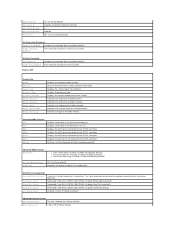
Front Panel Connectors USB two USB 2.0-compliant connectors Audio one slot supporting full-height cards two slots supporting full-height cards Specifications Computer Environment Temperature ranges: Operating 10° to 35° C (50° to 95° F) Storage - 40° to 65&#... a 2-ms half-sine pulse): Operating 40 G +/- 5% with pulse duration of 2 msec +/- 10% (equivalent to 20 inches/ sec [51 cm/sec]) 51 one headphone connector Expansion Slots PCI Express x16 PCI Express x1 PCI one slot supporting full-height cards one microphone connector;
Front Panel Connectors USB two USB 2.0-compliant connectors Audio one slot supporting full-height cards two slots supporting full-height cards Specifications Computer Environment Temperature ranges: Operating 10° to 35° C (50° to 95° F) Storage - 40° to 65&#... a 2-ms half-sine pulse): Operating 40 G +/- 5% with pulse duration of 2 msec +/- 10% (equivalent to 20 inches/ sec [51 cm/sec]) 51 one headphone connector Expansion Slots PCI Express x16 PCI Express x1 PCI one slot supporting full-height cards one microphone connector;


