
Service Manual
Page 1
Trademarks used in this text: Dell, the DELL logo, and Inspiron are trademarks of Dell Inc. Microsoft and Windows are not followed. Dell Inc. All rights reserved. February 2009 Rev. WARNING: A WARNING indicates a potential for property damage, personal injury, or death. ...of these materials in any proprietary interest in trademarks and trade names other countries. Dell™ Inspiron™ 535/537/545/546 Service Manual Technical Overview Before You Begin Computer Cover Front Bezel Memory PCI and PCI Express Cards Drives Models DCME and DCMF Fans Front I/O Panel ...
Trademarks used in this text: Dell, the DELL logo, and Inspiron are trademarks of Dell Inc. Microsoft and Windows are not followed. Dell Inc. All rights reserved. February 2009 Rev. WARNING: A WARNING indicates a potential for property damage, personal injury, or death. ...of these materials in any proprietary interest in trademarks and trade names other countries. Dell™ Inspiron™ 535/537/545/546 Service Manual Technical Overview Before You Begin Computer Cover Front Bezel Memory PCI and PCI Express Cards Drives Models DCME and DCMF Fans Front I/O Panel ...
Service Manual
Page 26
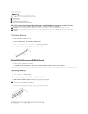
... Before You Begin. 2. Locate the memory modules on the bottom of the memory module connector. 3. If the memory module is difficult to remove, gently ease the memory module back and forth to Contents Page Memory Dell™ Inspiron™ 535/537/545/546 Service Manual Removing Memory Replacing Memory Recommended Memory Configuration Setting Up Dual Channel Memory Configuration WARNING: Before working inside...
... Before You Begin. 2. Locate the memory modules on the bottom of the memory module connector. 3. If the memory module is difficult to remove, gently ease the memory module back and forth to Contents Page Memory Dell™ Inspiron™ 535/537/545/546 Service Manual Removing Memory Replacing Memory Recommended Memory Configuration Setting Up Dual Channel Memory Configuration WARNING: Before working inside...
Service Manual
Page 27
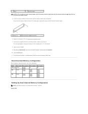
...and then turn them on. Log on Inspiron™ 535/537. 3 notch 4 memory module CAUTION: To avoid damage to the memory module, press the memory module straight down into the cutouts at each end of the memory module. 5. Replace the computer cover (...memory module. 1 cutouts (2) 2 securing clip (snapped in position) 6. To verify that memory size has changed, press to your computer. 9. If the message appears stating that the memory is not supported on to continue. 8. Insert the memory module into the connector until the memory module snaps into position. Inspiron 545...
...and then turn them on. Log on Inspiron™ 535/537. 3 notch 4 memory module CAUTION: To avoid damage to the memory module, press the memory module straight down into the cutouts at each end of the memory module. 5. Replace the computer cover (...memory module. 1 cutouts (2) 2 securing clip (snapped in position) 6. To verify that memory size has changed, press to your computer. 9. If the message appears stating that the memory is not supported on to continue. 8. Insert the memory module into the connector until the memory module snaps into position. Inspiron 545...

Service Manual
Page 28
1 Pair A: matched pair of memory 2 Pair B: matched pair of memory modules in connectors DIMM1 and modules in connectors DIMM2 and DIMM3 DIMM4 Inspiron 546 1 Pair B: matched pair of memory 2 Pair A: matched pair of memory modules in connectors DIMM3 and modules in connectors DIMM1 and DIMM4 DIMM2 Back to Contents Page
1 Pair A: matched pair of memory 2 Pair B: matched pair of memory modules in connectors DIMM1 and modules in connectors DIMM2 and DIMM3 DIMM4 Inspiron 546 1 Pair B: matched pair of memory 2 Pair A: matched pair of memory modules in connectors DIMM3 and modules in connectors DIMM1 and DIMM4 DIMM2 Back to Contents Page

Service Manual
Page 31
... and installed devices, the items listed in system setup unless you use System Setup, it is held down for extended periods of memory or set or change a user-selectable option such as listed. System Setup Screens Options List - Displays the asset tag for future...or remove any hardware in even intervals until the system setup screen appears. When the DELL logo appears, press immediately. Press to Contents Page System Setup Dell™ Inspiron™ 535/537/545/546 Service Manual Overview Entering System Setup Clearing Forgotten Passwords Clearing CMOS Settings Flashing the ...
... and installed devices, the items listed in system setup unless you use System Setup, it is held down for extended periods of memory or set or change a user-selectable option such as listed. System Setup Screens Options List - Displays the asset tag for future...or remove any hardware in even intervals until the system setup screen appears. When the DELL logo appears, press immediately. Press to Contents Page System Setup Dell™ Inspiron™ 535/537/545/546 Service Manual Overview Entering System Setup Clearing Forgotten Passwords Clearing CMOS Settings Flashing the ...

Service Manual
Page 32
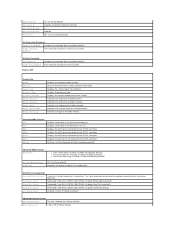
... detected. Network; Hard Drive; USB; Network; Full Speed; Memory Installed Memory Available Memory Speed Memory Channel Mode System Memory Type Indicates the amount of available memory. Indicates the amount of installed memory. Indicates the type of network devices. Standard CMOS Features Date Displays...Up Numlock Status Off; Hard Drive; CD/DVD; Disabled (Enabled by default) Module Bay Identifies the device installed in Inspiron 537 Integrated Peripherals USB Device Setting l USB Controller-Enabled or Disabled (Enabled by default) l USB Operation Mode-High ...
... detected. Network; Hard Drive; USB; Network; Full Speed; Memory Installed Memory Available Memory Speed Memory Channel Mode System Memory Type Indicates the amount of available memory. Indicates the amount of installed memory. Indicates the type of network devices. Standard CMOS Features Date Displays...Up Numlock Status Off; Hard Drive; CD/DVD; Disabled (Enabled by default) Module Bay Identifies the device installed in Inspiron 537 Integrated Peripherals USB Device Setting l USB Controller-Enabled or Disabled (Enabled by default) l USB Operation Mode-High ...
Service Manual
Page 33
...Disk; Hard Disk; Disable (Enabled by default) Advanced Chipset Features Init Display First PCI Slot, Onboard (PCI Slot by default) Video Memory Size 1 MB, 8 MB (8 MB by default) Set Supervisor Password Supervisor Password Installed; Last (Off by default) Displays the ...). Displays the SATA drives connected to change the user password Inspiron 545 System Info System BIOS Info Service Tag Processor Type Processor L2 Cache Memory Installed Memory Available Memory Speed Memory Channel Mode Memory Technology Displays the computer model number. Shows the BIOS version ...
...Disk; Hard Disk; Disable (Enabled by default) Advanced Chipset Features Init Display First PCI Slot, Onboard (PCI Slot by default) Video Memory Size 1 MB, 8 MB (8 MB by default) Set Supervisor Password Supervisor Password Installed; Last (Off by default) Displays the ...). Displays the SATA drives connected to change the user password Inspiron 545 System Info System BIOS Info Service Tag Processor Type Processor L2 Cache Memory Installed Memory Available Memory Speed Memory Channel Mode Memory Technology Displays the computer model number. Shows the BIOS version ...

Service Manual
Page 34
... Set User Password User Password Change User Password Inspiron 546 Installed; Not Installed (Not Installed by default) Auto Power On Enabled; Displays the amount of processor Level 2 cache Indicates the amount of available memory. Displays the SATA drives connected to the SATA... the user password System Info BIOS Info System Asset Tag Service Tag Processor Type CPU Speed Processor L2 Cache Memory Installed Memory Available Memory Speed Memory Channel Mode Memory Technology Shows the BIOS version number and date information. On; Not Installed (Not Installed by default) l...
... Set User Password User Password Change User Password Inspiron 546 Installed; Not Installed (Not Installed by default) Auto Power On Enabled; Displays the amount of processor Level 2 cache Indicates the amount of available memory. Displays the SATA drives connected to the SATA... the user password System Info BIOS Info System Asset Tag Service Tag Processor Type CPU Speed Processor L2 Cache Memory Installed Memory Available Memory Speed Memory Channel Mode Memory Technology Shows the BIOS version number and date information. On; Not Installed (Not Installed by default) l...

Service Manual
Page 35
...bottom- right corner of the user password Set Supervisor Password Set the supervisor password through this feature to a USB device such as a floppy drive, memory key, or CD-RW drive. 1. PCI-E 1X Slot; Disabled; Disabled (Hard Drive by default) Disabled; S3(STR) (S3(STR) by ...Device Setting l AMD Live!-indicates the AMD Live! Hard Drive; You can also use this feature, for the Current Boot You can run the Dell Diagnostics on (or restart) your computer to restart your computer. 3. Enabled (Enabled by default) Off; Enabled (Enabled by default) Disabled; ON ...
...bottom- right corner of the user password Set Supervisor Password Set the supervisor password through this feature to a USB device such as a floppy drive, memory key, or CD-RW drive. 1. PCI-E 1X Slot; Disabled; Disabled (Hard Drive by default) Disabled; S3(STR) (S3(STR) by ...Device Setting l AMD Live!-indicates the AMD Live! Hard Drive; You can also use this feature, for the Current Boot You can run the Dell Diagnostics on (or restart) your computer to restart your computer. 3. Enabled (Enabled by default) Off; Enabled (Enabled by default) Disabled; ON ...
Service Manual
Page 36
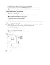
...keys to a USB device, the device must be used for Future Boots 1. Inspiron 535/537 Inspiron 545 Use the arrow keys to highlight the Boot Device Configuration menu option and press to a USB memory key, highlight USB Flash Device and press . NOTE: The location of devices.... 4. Remove the computer cover (see the Regulatory Compliance Homepage at www.dell.com/regulatory_compliance. 1....
...keys to a USB device, the device must be used for Future Boots 1. Inspiron 535/537 Inspiron 545 Use the arrow keys to highlight the Boot Device Configuration menu option and press to a USB memory key, highlight USB Flash Device and press . NOTE: The location of devices.... 4. Remove the computer cover (see the Regulatory Compliance Homepage at www.dell.com/regulatory_compliance. 1....

Service Manual
Page 40
... assembly (see the Regulatory Compliance Homepage at www.dell.com/regulatory_compliance. Disconnect all cables as you remove them correctly after the board is replaced. 7. Inspiron 535/537 1 screws (6) 2 system board Inspiron 545/546 For additional safety best practices information, see ...memory modules can re-route them so that you can be installed in the same location after installing the new system board. 8. WARNING: To guard against electrical shock, always unplug your computer from the system board. 9. Back to Contents Page System Board Dell™ Inspiron™ 535/537/545...
... assembly (see the Regulatory Compliance Homepage at www.dell.com/regulatory_compliance. Disconnect all cables as you remove them correctly after the board is replaced. 7. Inspiron 535/537 1 screws (6) 2 system board Inspiron 545/546 For additional safety best practices information, see ...memory modules can re-route them so that you can be installed in the same location after installing the new system board. 8. WARNING: To guard against electrical shock, always unplug your computer from the system board. 9. Back to Contents Page System Board Dell™ Inspiron™ 535/537/545...

Service Manual
Page 42
Replace any add-in cards on . Connect your computer and devices to Contents Page Replace the computer cover (see Replacing Memory). 7. 6. Replace the memory modules into the memory sockets at the same locations from which you removed them on the system board (see Replacing PCI and PCI Express Cards). 8. Back to an electrical outlet, and turn them (see Replacing the Computer Cover). 9.
Replace any add-in cards on . Connect your computer and devices to Contents Page Replace the computer cover (see Replacing Memory). 7. 6. Replace the memory modules into the memory sockets at the same locations from which you removed them on the system board (see Replacing PCI and PCI Express Cards). 8. Back to an electrical outlet, and turn them (see Replacing the Computer Cover). 9.
Setup Guide
Page 5
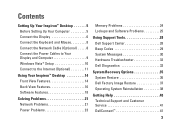
...Power Cables to Your Display and Computer 9 Windows Vista® Setup 10 Connect to the Internet (Optional 11 Using Your Inspiron™ Desktop 14 Front View Features 14 Back View Features 16 Software Features 18 Solving Problems 21 Network Problems 21 Power Problems 23... Memory Problems 24 Lockups and Software Problems 25 Using Support Tools 28 Dell Support Center 28 Beep Codes 29 System Messages 30 Hardware Troubleshooter 32 Dell Diagnostics 32 System Recovery Options 35 System Restore 36 Dell Factory Image Restore 37 Operating ...
...Power Cables to Your Display and Computer 9 Windows Vista® Setup 10 Connect to the Internet (Optional 11 Using Your Inspiron™ Desktop 14 Front View Features 14 Back View Features 16 Software Features 18 Solving Problems 21 Network Problems 21 Power Problems 23... Memory Problems 24 Lockups and Software Problems 25 Using Support Tools 28 Dell Support Center 28 Beep Codes 29 System Messages 30 Hardware Troubleshooter 32 Dell Diagnostics 32 System Recovery Options 35 System Restore 36 Dell Factory Image Restore 37 Operating ...

Setup Guide
Page 17
... state. • Power light is in the center of your computer. 4 Power button - Use the optical drive to USB devices such as memory keys, digital cameras, and MP3 players. 3 Headphone connector - The light in power-on the back of this button indicates the power state:... Solid white - Supports a Media Card Reader, or an additional hard drive. 9 Optical drive panel (2) - the computer is either turned off . Using Your Inspiron™ Desktop • Solid amber - Connects to play a CD/DVD/Blu-ray Disc™. 15 NOTE: To connect to the hard drive. 6 FlexBay ...
... state. • Power light is in the center of your computer. 4 Power button - Use the optical drive to USB devices such as memory keys, digital cameras, and MP3 players. 3 Headphone connector - The light in power-on the back of this button indicates the power state:... Solid white - Supports a Media Card Reader, or an additional hard drive. 9 Optical drive panel (2) - the computer is either turned off . Using Your Inspiron™ Desktop • Solid amber - Connects to play a CD/DVD/Blu-ray Disc™. 15 NOTE: To connect to the hard drive. 6 FlexBay ...
Setup Guide
Page 25
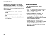
... the keyboard, move the pointer on the trackpad or a connected mouse, or press the power button to remove and then reinstall the memory modules (for information on removing and replacing memory modules, see the Service Manual on properly. • Ensure that the power strip is on . The computer is either turned off... computer is receiving electrical power, but a device might be a possible problem with another device, such as a lamp. • Ensure that the computer turns on the Dell Support website at support...
... the keyboard, move the pointer on the trackpad or a connected mouse, or press the power button to remove and then reinstall the memory modules (for information on removing and replacing memory modules, see the Service Manual on properly. • Ensure that the power strip is on . The computer is either turned off... computer is receiving electrical power, but a device might be a possible problem with another device, such as a lamp. • Ensure that the computer turns on the Dell Support website at support...
Setup Guide
Page 26
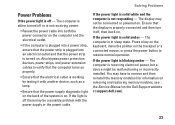
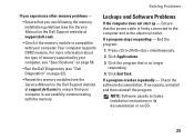
...) to the same electrical outlet. An unwanted signal is successfully communicating with the memory. 24 If necessary, install additional memory (see the Service Manual on the Dell Support website at support.dell.com). • Reseat the memory modules (see if that your computer - Solving Problems If you are : • Power, keyboard, and mouse extension cables...
...) to the same electrical outlet. An unwanted signal is successfully communicating with the memory. 24 If necessary, install additional memory (see the Service Manual on the Dell Support website at support.dell.com). • Reseat the memory modules (see if that your computer - Solving Problems If you are : • Power, keyboard, and mouse extension cables...
Setup Guide
Page 27
... computer is successfully communicating with your computer, see "Specifications" on page 50. • Run the Dell Diagnostics (see "Dell Diagnostics" on page 32). • Reseat the memory modules (see the Service Manual on the Dell Support website at support.dell.com) to the electrical outlet. NOTE: Software usually includes installation instructions in its documentation or...
... computer is successfully communicating with your computer, see "Specifications" on page 50. • Run the Dell Diagnostics (see "Dell Diagnostics" on page 32). • Reseat the memory modules (see the Service Manual on the Dell Support website at support.dell.com) to the electrical outlet. NOTE: Software usually includes installation instructions in its documentation or...
Setup Guide
Page 31
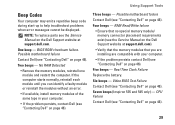
... or reinstall the modules without an error. • If available, install memory modules of the same type in your computer. • If the problem persists contact Dell (see the Service Manual on the Dell Support website at support.dell.com. Seven beeps (Inspiron 535 and 545 only) - Four beeps - BIOS ROM checksum failure. Five beeps - NOTE...
... or reinstall the modules without an error. • If available, install memory modules of the same type in your computer. • If the problem persists contact Dell (see the Service Manual on the Dell Support website at support.dell.com. Seven beeps (Inspiron 535 and 545 only) - Four beeps - BIOS ROM checksum failure. Five beeps - NOTE...

Setup Guide
Page 50
...of your computer may void your operating system. NOTE: Drivers and documentation updates can be found on the Dell™ Support website at support.dell.com. run a diagnostic program for your computer, reinstall desktop system software, or update drivers for your...memory, or a new hard drive. upgrade your computer, and readme files. learn more about your computer. 48 reinstall or replace a worn or defective part. Check your warranty and return policies before working inside your operating system, maintaining peripherals, RAID, Internet, Bluetooth®, networking, and e-mail. INSPIRON...
...of your computer may void your operating system. NOTE: Drivers and documentation updates can be found on the Dell™ Support website at support.dell.com. run a diagnostic program for your computer, reinstall desktop system software, or update drivers for your...memory, or a new hard drive. upgrade your computer, and readme files. learn more about your computer. 48 reinstall or replace a worn or defective part. Check your warranty and return policies before working inside your operating system, maintaining peripherals, RAID, Internet, Bluetooth®, networking, and e-mail. INSPIRON...

Setup Guide
Page 55
...® Dual-Core Intel Core™2 Duo Intel Core2 Quad (537 only) 545 Intel Celeron Intel Pentium Dual-Core Intel Core2 Duo Intel Core2 Quad 546 AMD™ Sempron™ AMD Athlon™ AMD Athlon X2 AMD Phenom™ Memory Connectors two four four Minimum 1 GB (1 x 1 GB DIMM) 1 GB...) 8 GB (4 x 2 GB DIMMs) Memory type 800-MHz DDR2 DIMM; non-ECC memory only Capacities 1 GB and 2 GB 1 GB and 2 GB 1 GB and 2 GB NOTE: For instructions on upgrading your memory, see the Service Manual on the Dell Support website at support.dell.com. 53 non-ECC memory only 800-MHz DDR2 DIMM; non...
...® Dual-Core Intel Core™2 Duo Intel Core2 Quad (537 only) 545 Intel Celeron Intel Pentium Dual-Core Intel Core2 Duo Intel Core2 Quad 546 AMD™ Sempron™ AMD Athlon™ AMD Athlon X2 AMD Phenom™ Memory Connectors two four four Minimum 1 GB (1 x 1 GB DIMM) 1 GB...) 8 GB (4 x 2 GB DIMMs) Memory type 800-MHz DDR2 DIMM; non-ECC memory only Capacities 1 GB and 2 GB 1 GB and 2 GB 1 GB and 2 GB NOTE: For instructions on upgrading your memory, see the Service Manual on the Dell Support website at support.dell.com. 53 non-ECC memory only 800-MHz DDR2 DIMM; non...


