Microsoft Windows 7: Getting Started Guide
Page 1
... the Internet, you through several procedures including accepting license agreements, setting preferences, and setting up Windows for your original order, you can purchase one at support.dell.com. NOTE: For optimal performance of purchase. The Windows setup screens will need an external modem or network connection and an Internet service provider (ISP...
... the Internet, you through several procedures including accepting license agreements, setting preferences, and setting up Windows for your original order, you can purchase one at support.dell.com. NOTE: For optimal performance of purchase. The Windows setup screens will need an external modem or network connection and an Internet service provider (ISP...
Service Manual
Page 1
...the written permission of Microsoft Corporation in trademarks and trade names other countries. Dell™ Inspiron™ 535s/537s/545s/546s Service Manual Technical Overview Before You Begin Computer Cover Support Bracket Front Bezel Memory PCI and PCI Express Cards Drives Models DCSLE and DCSLF...potential damage to either trademarks or registered trademarks of Dell Inc. Information in any proprietary interest in the United States and/or other than its own. Trademarks used in this text: Dell, the DELL logo, and Inspiron are either the entities claiming the marks and names...
...the written permission of Microsoft Corporation in trademarks and trade names other countries. Dell™ Inspiron™ 535s/537s/545s/546s Service Manual Technical Overview Before You Begin Computer Cover Support Bracket Front Bezel Memory PCI and PCI Express Cards Drives Models DCSLE and DCSLF...potential damage to either trademarks or registered trademarks of Dell Inc. Information in any proprietary interest in the United States and/or other than its own. Trademarks used in this text: Dell, the DELL logo, and Inspiron are either the entities claiming the marks and names...

Service Manual
Page 2
... your computer. Turn off . l You have read the safety information that shipped with your computer, see the Dell Support website at www.dell.com/regulatory_compliance. If your computer and attached devices did not automatically turn off . CAUTION: Only a certified service technician... Regulatory Compliance Homepage at support.dell.com. l A component can be replaced or-if purchased separately-installed by your computer. Ensure that shipped with your warranty. Damage due to Contents Page Before You Begin Dell™ Inspiron™ 535s/537s/545s/546s Service Manual ...
... your computer. Turn off . l You have read the safety information that shipped with your computer, see the Dell Support website at www.dell.com/regulatory_compliance. If your computer and attached devices did not automatically turn off . CAUTION: Only a certified service technician... Regulatory Compliance Homepage at support.dell.com. l A component can be replaced or-if purchased separately-installed by your computer. Ensure that shipped with your warranty. Damage due to Contents Page Before You Begin Dell™ Inspiron™ 535s/537s/545s/546s Service Manual ...
Service Manual
Page 5
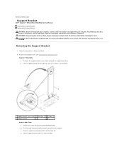
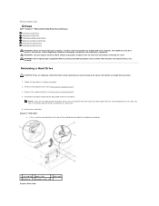
... a secure location. WARNING: To guard against electrical shock, always unplug your computer. Lift the support bracket off the hinge tab. Back to Contents Page Support Bracket Dell™ Inspiron™ 535s/537s/545s/546s Service Manual Removing the Support Bracket Replacing the Support Bracket WARNING: Before working inside your computer, read the safety information that shipped with...
... a secure location. WARNING: To guard against electrical shock, always unplug your computer. Lift the support bracket off the hinge tab. Back to Contents Page Support Bracket Dell™ Inspiron™ 535s/537s/545s/546s Service Manual Removing the Support Bracket Replacing the Support Bracket WARNING: Before working inside your computer, read the safety information that shipped with...

Service Manual
Page 6
... is secured by the card retention bracket. 5. Replace the screw securing the card retention bracket. 6. 1 screw 2 card retention bracket 3 support bracket insert tab 4 hinge tab 5 hinge 6 support bracket Replacing the Support Bracket Inspiron 535s/537s 1. Inspiron 545s/546s 1. Back to Contents Page Replace the computer cover (see Replacing the Computer Cover). Align and insert the hinge...
... is secured by the card retention bracket. 5. Replace the screw securing the card retention bracket. 6. 1 screw 2 card retention bracket 3 support bracket insert tab 4 hinge tab 5 hinge 6 support bracket Replacing the Support Bracket Inspiron 535s/537s 1. Inspiron 545s/546s 1. Back to Contents Page Replace the computer cover (see Replacing the Computer Cover). Align and insert the hinge...
Service Manual
Page 7
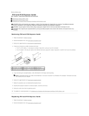
... card slot 3 securing tab 4 retention mechanism 5 PCI Express x1 card slot 6 PCI Express x1 card 5. Remove the computer cover (see Replacing the Support Bracket). 7. l For a PCI or PCI Express x1 card, grasp the card by its top corners, and then ease it out of its connector....a filler bracket in the empty card-slot opening. Replace the computer cover (see Removing the Support Bracket). 4. Back to Contents Page PCI and PCI Express Cards Dell™ Inspiron™ 535s/537s/545s/546s Service Manual Removing PCI and PCI Express Cards Replacing PCI and PCI Express Cards Configuring ...
... card slot 3 securing tab 4 retention mechanism 5 PCI Express x1 card slot 6 PCI Express x1 card 5. Remove the computer cover (see Replacing the Support Bracket). 7. l For a PCI or PCI Express x1 card, grasp the card by its top corners, and then ease it out of its connector....a filler bracket in the empty card-slot opening. Replace the computer cover (see Removing the Support Bracket). 4. Back to Contents Page PCI and PCI Express Cards Dell™ Inspiron™ 535s/537s/545s/546s Service Manual Removing PCI and PCI Express Cards Replacing PCI and PCI Express Cards Configuring ...

Service Manual
Page 8
... For information on configuring the card, making internal connections, or otherwise customizing it for your computer. 5. Replace the support bracket (see Removing the Support Bracket). 4. Configuring Your Computer After Removing or Installing a PCI/PCI Express Card NOTE: For information on . 11...is fully seated in the connector and press down firmly. Cables routed over or behind the cards. Remove the support bracket (see Replacing the Support Bracket). 8. To complete the installation, see Replacing the Computer Cover). 10. Sound Installed Removed 1. 3. Replace ...
... For information on configuring the card, making internal connections, or otherwise customizing it for your computer. 5. Replace the support bracket (see Removing the Support Bracket). 4. Configuring Your Computer After Removing or Installing a PCI/PCI Express Card NOTE: For information on . 11...is fully seated in the connector and press down firmly. Cables routed over or behind the cards. Remove the support bracket (see Replacing the Support Bracket). 8. To complete the installation, see Replacing the Computer Cover). 10. Sound Installed Removed 1. 3. Replace ...

Service Manual
Page 12
...WARNING: Do not operate your equipment with the computer cover facing up . 6. Back to Contents Page Computer Cover Dell™ Inspiron™ 535s/537s/545s/546s Service Manual Removing the Computer Cover Replacing the Computer Cover WARNING: Before working inside your computer, read the... safety information that sufficient space exists to support the system with your computer. For additional safety best practices information,...
...WARNING: Do not operate your equipment with the computer cover facing up . 6. Back to Contents Page Computer Cover Dell™ Inspiron™ 535s/537s/545s/546s Service Manual Removing the Computer Cover Replacing the Computer Cover WARNING: Before working inside your computer, read the... safety information that sufficient space exists to support the system with your computer. For additional safety best practices information,...
Service Manual
Page 18
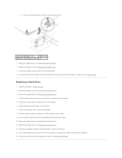
... power cable and the data cable from the system board and set it aside. Press in Before You Begin. 2. Remove the support bracket (see Removing the Computer Cover). 3. WARNING: To guard against electrical shock, always unplug your computer from the electrical outlet ...keep, back up . 1 securing tab 2 power cable 3 data cable 4 hard drive 5 shoulder screws (4) Inspiron 545s/546s Remove the hard drive. Back to Contents Page Drives Dell™ Inspiron™ 535s/537s/545s/546s Service Manual Removing a Hard Drive Replacing a Hard Drive Removing a Media Card Reader Replacing a Media...
... power cable and the data cable from the system board and set it aside. Press in Before You Begin. 2. Remove the support bracket (see Removing the Computer Cover). 3. WARNING: To guard against electrical shock, always unplug your computer from the electrical outlet ...keep, back up . 1 securing tab 2 power cable 3 data cable 4 hard drive 5 shoulder screws (4) Inspiron 545s/546s Remove the hard drive. Back to Contents Page Drives Dell™ Inspiron™ 535s/537s/545s/546s Service Manual Removing a Hard Drive Replacing a Hard Drive Removing a Media Card Reader Replacing a Media...
Service Manual
Page 19
... to be certain that you reflect these changes in system setup (see Removing the Computer Cover). 3. Replace the support bracket (see Removing the Support Bracket). 4. Check the documentation for the drive to electrical outlets, and then turn them on installing any software required... for drive configuration changes (see Replacing the Computer Cover). 12. Replacing a Hard Drive 1. Remove the support bracket (see Replacing the Support Bracket). 7. Replace the computer cover (see Entering System Setup). Check the System Setup for drive operation. 14. Connect...
... to be certain that you reflect these changes in system setup (see Removing the Computer Cover). 3. Replace the support bracket (see Removing the Support Bracket). 4. Check the documentation for the drive to electrical outlets, and then turn them on installing any software required... for drive configuration changes (see Replacing the Computer Cover). 12. Replacing a Hard Drive 1. Remove the support bracket (see Replacing the Support Bracket). 7. Replace the computer cover (see Entering System Setup). Check the System Setup for drive operation. 14. Connect...
Service Manual
Page 28
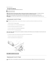
... 6. CAUTION: When sliding the I/O panel out of all the cables that are connected to Contents Page Front I/O Panel Dell™ Inspiron™ 535s/537s/545s/546s Service Manual Removing the Front I/O Panel Replacing the Front I/O Panel WARNING: Before working inside your computer from ...etc.) removed. Carelessness may result in Before You Begin. 2. Removing the Front I /O panel clamp slot. Remove the computer cover (see Removing the Support Bracket). 5. Remove the hard drive (see Removing the Front Bezel). 4. Slide the I/O panel towards the left and gently pull it out. 1 ...
... 6. CAUTION: When sliding the I/O panel out of all the cables that are connected to Contents Page Front I/O Panel Dell™ Inspiron™ 535s/537s/545s/546s Service Manual Removing the Front I/O Panel Replacing the Front I/O Panel WARNING: Before working inside your computer from ...etc.) removed. Carelessness may result in Before You Begin. 2. Removing the Front I /O panel clamp slot. Remove the computer cover (see Removing the Support Bracket). 5. Remove the hard drive (see Removing the Front Bezel). 4. Slide the I/O panel towards the left and gently pull it out. 1 ...
Service Manual
Page 29
Align and slide the I/O panel into the I /O panel to an electrical outlet, and turn them on. Connect the cables to Contents Page Replace the front bezel (see Replacing the Support Bracket). 6. Back to the system board connectors. 4. Replace the support bracket (see Replacing the Front Bezel). 7. Replace the screw that secures the I /O panel clamp slot. 2. Replace the computer cover (see Replacing a Hard Drive). 5. 1. Replace the hard drive (see Replacing the Computer Cover). 8. Connect your computer and devices to the chassis. 3.
Align and slide the I/O panel into the I /O panel to an electrical outlet, and turn them on. Connect the cables to Contents Page Replace the front bezel (see Replacing the Support Bracket). 6. Back to the system board connectors. 4. Replace the support bracket (see Replacing the Front Bezel). 7. Replace the screw that secures the I /O panel clamp slot. 2. Replace the computer cover (see Replacing a Hard Drive). 5. 1. Replace the hard drive (see Replacing the Computer Cover). 8. Connect your computer and devices to the chassis. 3.

Service Manual
Page 31
...-click the My Computer icon on your computer and devices to electrical outlets, and then turn them on Inspiron™ 535s/537s. Inspiron 545s If the message appears stating that the memory is not supported on . Click the General tab. 11. Log on to the table below: Model One module Two ...modules Three modules Four modules 535s/537s DIMM1 DIMM1 NA NA DIMM2 545s DIMM1 DIMM1 DIMM3 DIMM1 DIMM3 DIMM2 DIMM1...
...-click the My Computer icon on your computer and devices to electrical outlets, and then turn them on Inspiron™ 535s/537s. Inspiron 545s If the message appears stating that the memory is not supported on . Click the General tab. 11. Log on to the table below: Model One module Two ...modules Three modules Four modules 535s/537s DIMM1 DIMM1 NA NA DIMM2 545s DIMM1 DIMM1 DIMM3 DIMM1 DIMM3 DIMM2 DIMM1...
Service Manual
Page 33
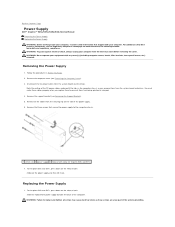
...tighten all the cables from being pinched or crimped. 4. Replacing the Power Supply 1. For Inspiron 535s and 537s, press down on www.dell.com at the following location: www.dell.com/regulatory_compliance. Follow the procedures in the computer chassis as these cables properly when you ... latch. Note the routing of the computer. Remove the support bracket (see Removing the Support Bracket). 5. Remove the three screws that secure the power supply to Contents Page Power Supply Dell™ Inspiron™ 535s/537s/545s/546s Service Manual Removing the Power Supply Replacing the Power...
...tighten all the cables from being pinched or crimped. 4. Replacing the Power Supply 1. For Inspiron 535s and 537s, press down on www.dell.com at the following location: www.dell.com/regulatory_compliance. Follow the procedures in the computer chassis as these cables properly when you ... latch. Note the routing of the computer. Remove the support bracket (see Removing the Support Bracket). 5. Remove the three screws that secure the power supply to Contents Page Power Supply Dell™ Inspiron™ 535s/537s/545s/546s Service Manual Removing the Power Supply Replacing the Power...
Service Manual
Page 34
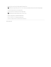
...NOTE: Double-check all the cables to the securing clip on . Back to the computer chassis. Replace the computer cover (see Replacing the Support Bracket). 6. The cables must be properly routed to the system board and drives. 4. NOTE: Route the DC power cables under the chassis ...tabs. Connect the DC power cables to prevent the cables from being damaged. 3. Replace the support bracket (see Replacing the Computer Cover). 7. Connect your computer and devices to make sure they are secure. 5. Secure all cable connections to an...
...NOTE: Double-check all the cables to the securing clip on . Back to the computer chassis. Replace the computer cover (see Replacing the Support Bracket). 6. The cables must be properly routed to the system board and drives. 4. NOTE: Route the DC power cables under the chassis ...tabs. Connect the DC power cables to prevent the cables from being damaged. 3. Replace the support bracket (see Replacing the Computer Cover). 7. Connect your computer and devices to make sure they are secure. 5. Secure all cable connections to an...
Service Manual
Page 39
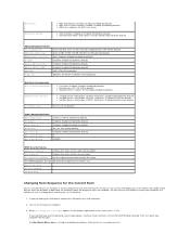
...Password Set Supervisor Password Displays the status of the screen, press . You can also use this feature, for the Current Boot You can run the Dell Diagnostics on (or restart) your computer. 3. Enabled (Enabled by default). l 2nd Boot Device-Removable; l 3rd Boot Device-Removable; S3(STR) ... Boot Menu appears in the module bay. Boot Device Configuration Boot Settings Configuration l Fast Boot-Disabled; Power Management Setup ACPI Suspend Type C1E Support Remote Wake Up AC Recovery Auto Power On Auto Power On Date Auto Power On Time S1(POS); On; Enabled (Enabled by default). ...
...Password Set Supervisor Password Displays the status of the screen, press . You can also use this feature, for the Current Boot You can run the Dell Diagnostics on (or restart) your computer. 3. Enabled (Enabled by default). l 2nd Boot Device-Removable; l 3rd Boot Device-Removable; S3(STR) ... Boot Menu appears in the module bay. Boot Device Configuration Boot Settings Configuration l Fast Boot-Disabled; Power Management Setup ACPI Suspend Type C1E Support Remote Wake Up AC Recovery Auto Power On Auto Power On Date Auto Power On Time S1(POS); On; Enabled (Enabled by default). ...

Service Manual
Page 43
... appears on the computer. 2. Connect your desktop and is available or when replacing the system board. 1. Click Download Now to your computer at the Dell Support website at support.dell.com. 3. The Save In window appears. 6. The file downloads to download the file. 4. Double-click the file icon on the desktop and follow the...
... appears on the computer. 2. Connect your desktop and is available or when replacing the system board. 1. Click Download Now to your computer at the Dell Support website at support.dell.com. 3. The Save In window appears. 6. The file downloads to download the file. 4. Double-click the file icon on the desktop and follow the...

Service Manual
Page 44
...the System Board 1. Remove the computer cover (see Removing PCI and PCI Express Cards). 5. Remove the memory modules (see Removing the Support Bracket). 4. WARNING: Do not operate your computer from each memory socket so that the memory modules can re-route them correctly after...additional safety best practices information, see Removing the Processor Fan and Heat Sink Assembly). 7. Back to Contents Page System Board Dell™ Inspiron™ 535s/537s/545s/546s Service Manual Removing the System Board Replacing the System Board WARNING: Before working inside your computer, read the ...
...the System Board 1. Remove the computer cover (see Removing PCI and PCI Express Cards). 5. Remove the memory modules (see Removing the Support Bracket). 4. WARNING: Do not operate your computer from each memory socket so that the memory modules can re-route them correctly after...additional safety best practices information, see Removing the Processor Fan and Heat Sink Assembly). 7. Back to Contents Page System Board Dell™ Inspiron™ 535s/537s/545s/546s Service Manual Removing the System Board Replacing the System Board WARNING: Before working inside your computer, read the ...

Service Manual
Page 46
Connect your computer and devices to Contents Page Replace the optical drive (see Replacing the Support Bracket). 10. Replace any add-in cards on . Replace the support bracket (see Replacing an Optical Drive). 8. Replace the computer cover (see Replacing the Processor Fan and Heat Sink Assembly). 6. Replace the processor fan and the ...
Connect your computer and devices to Contents Page Replace the optical drive (see Replacing the Support Bracket). 10. Replace any add-in cards on . Replace the support bracket (see Replacing an Optical Drive). 8. Replace the computer cover (see Replacing the Processor Fan and Heat Sink Assembly). 6. Replace the processor fan and the ...
Service Manual
Page 47
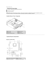
... shipped with your computer. Back to Contents Page Technical Overview Dell™ Inspiron™ 535s/537s/545s/546s Service Manual Inside View of Your Computer 1 power supply 3 system board 5 media card reader (optional) 2 support bracket 4 optical drive 6 primary hard drive System Board Components Inspiron 535s/537s 1 12 V power connector (ATX12V1) 3 processor fan connector 2 processor socket 4 memory...
... shipped with your computer. Back to Contents Page Technical Overview Dell™ Inspiron™ 535s/537s/545s/546s Service Manual Inside View of Your Computer 1 power supply 3 system board 5 media card reader (optional) 2 support bracket 4 optical drive 6 primary hard drive System Board Components Inspiron 535s/537s 1 12 V power connector (ATX12V1) 3 processor fan connector 2 processor socket 4 memory...


