Service Manual
Page 1
.... Reproduction of these materials in any proprietary interest in this text: Dell, the DELL logo, and Inspiron are trademarks of Dell Inc. Dell™ Inspiron™ 535s/537s/545s/546s Service Manual Technical Overview Before You Begin Computer Cover Support Bracket Front Bezel Memory PCI and PCI Express Cards Drives Models DCSLE and DCSLF Fans Front I/O Panel Processor... strictly forbidden. Information in the United States and/or other than its own. CAUTION: A CAUTION indicates potential damage to change without the written permission of Dell Inc.;
.... Reproduction of these materials in any proprietary interest in this text: Dell, the DELL logo, and Inspiron are trademarks of Dell Inc. Dell™ Inspiron™ 535s/537s/545s/546s Service Manual Technical Overview Before You Begin Computer Cover Support Bracket Front Bezel Memory PCI and PCI Express Cards Drives Models DCSLE and DCSLF Fans Front I/O Panel Processor... strictly forbidden. Information in the United States and/or other than its own. CAUTION: A CAUTION indicates potential damage to change without the written permission of Dell Inc.;
Service Manual
Page 30
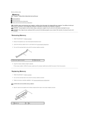
... the securing clip at each end of the memory module connector. 3. If the memory module is difficult to remove, gently ease the memory module back and forth to Contents Page Memory Dell™ Inspiron™ 535s/537s/545s/546s Service Manual Removing Memory Replacing Memory Recommended Memory Configuration Setting Up Dual Channel Memory Configuration WARNING: Before working inside your computer, read...
... the securing clip at each end of the memory module connector. 3. If the memory module is difficult to remove, gently ease the memory module back and forth to Contents Page Memory Dell™ Inspiron™ 535s/537s/545s/546s Service Manual Removing Memory Replacing Memory Recommended Memory Configuration Setting Up Dual Channel Memory Configuration WARNING: Before working inside your computer, read...

Service Manual
Page 31
...10. Right-click the My Computer icon on Inspiron™ 535s/537s. Recommended Memory Configuration While installing or replacing memory, refer to the table below: Model One module Two modules Three modules Four modules 535s/537s DIMM1 DIMM1 NA NA DIMM2 545s DIMM1 DIMM1 DIMM3...the message appears stating that the memory is not supported on your computer. 9. Inspiron 545s 3 notch 4 memory module CAUTION: To avoid damage to the memory module, press the memory module straight down into the connector while you insert the memory module correctly, the securing clips snap...
...10. Right-click the My Computer icon on Inspiron™ 535s/537s. Recommended Memory Configuration While installing or replacing memory, refer to the table below: Model One module Two modules Three modules Four modules 535s/537s DIMM1 DIMM1 NA NA DIMM2 545s DIMM1 DIMM1 DIMM3...the message appears stating that the memory is not supported on your computer. 9. Inspiron 545s 3 notch 4 memory module CAUTION: To avoid damage to the memory module, press the memory module straight down into the connector while you insert the memory module correctly, the securing clips snap...

Service Manual
Page 32
1 Pair A: matched pair of memory 2 Pair B: matched pair of memory modules in connectors DIMM1 and modules in connectors DIMM2 and DIMM3 DIMM4 Inspiron 546s 1 Pair B: matched pair of memory 2 Pair A: matched pair of memory modules in connectors DIMM3 and modules in connectors DIMM1 and DIMM4 DIMM2 Back to Contents Page
1 Pair A: matched pair of memory 2 Pair B: matched pair of memory modules in connectors DIMM1 and modules in connectors DIMM2 and DIMM3 DIMM4 Inspiron 546s 1 Pair B: matched pair of memory 2 Pair A: matched pair of memory modules in connectors DIMM3 and modules in connectors DIMM1 and DIMM4 DIMM2 Back to Contents Page
Service Manual
Page 35
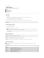
... your computer, including installed hardware, power conservation, and security features. Displays the processor type. l To read the current amount of memory or set or change a user-selectable option such as listed. NOTE: Keyboard failure may not appear exactly as the user password. and..., the items listed in system setup unless you are an expert computer user. Back to Contents Page System Setup Dell™ Inspiron™ 535s/537s/545s/546s Service Manual Overview Entering System Setup Clearing Forgotten Passwords Clearing CMOS Settings Flashing the BIOS Overview Use System Setup...
... your computer, including installed hardware, power conservation, and security features. Displays the processor type. l To read the current amount of memory or set or change a user-selectable option such as listed. NOTE: Keyboard failure may not appear exactly as the user password. and..., the items listed in system setup unless you are an expert computer user. Back to Contents Page System Setup Dell™ Inspiron™ 535s/537s/545s/546s Service Manual Overview Entering System Setup Clearing Forgotten Passwords Clearing CMOS Settings Flashing the BIOS Overview Use System Setup...
Service Manual
Page 36
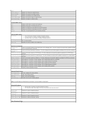
..., MAX (128 MB by default). Fifth Boot Device Removable Dev.; Cache Memory Installed Memory Available Memory Speed Memory Channel Mode System Memory Type Indicates the amount of installed memory. Indicates the amount of CD/DVD drives. Standard CMOS Features Date Displays current date in Inspiron 537s Integrated Peripherals USB Device Setting l USB Controller-Enabled or Disabled (Enabled by...
..., MAX (128 MB by default). Fifth Boot Device Removable Dev.; Cache Memory Installed Memory Available Memory Speed Memory Channel Mode System Memory Type Indicates the amount of installed memory. Indicates the amount of CD/DVD drives. Standard CMOS Features Date Displays current date in Inspiron 537s Integrated Peripherals USB Device Setting l USB Controller-Enabled or Disabled (Enabled by...
Service Manual
Page 37
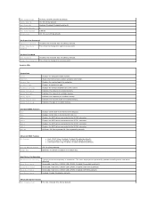
...00 Off; Disabled (Disabled by default). On; Displays the service tag of installed memory. Indicates the frequency of installed memory. Indicates the type of installed memory. Advanced BIOS Features CPU Feature l Limit CPUID Value-Enabled; Boot Device Configuration Hard ...Enter to set the device priority of processor Level 2 cache. Inspiron 545s System Info System BIOS Info Service Tag Processor Type Processor L2 Cache Memory Installed Memory Available Memory Speed Memory Channel Mode Memory Technology Displays the computer model number. l Core Multi-Processing-Enabled...
...00 Off; Disabled (Disabled by default). On; Displays the service tag of installed memory. Indicates the frequency of installed memory. Indicates the type of installed memory. Advanced BIOS Features CPU Feature l Limit CPUID Value-Enabled; Boot Device Configuration Hard ...Enter to set the device priority of processor Level 2 cache. Inspiron 545s System Info System BIOS Info Service Tag Processor Type Processor L2 Cache Memory Installed Memory Available Memory Speed Memory Channel Mode Memory Technology Displays the computer model number. l Core Multi-Processing-Enabled...
Service Manual
Page 38
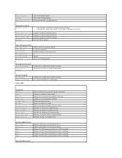
...(STR) (S3(STR) by default). Set User Password User Password Change User Password Inspiron 546s Installed; Displays the amount of installed memory. Indicates the channel mode of installed memory. Power Management Setup ACPI Suspend Type S1(POS); Off (On by default). On...Asset Tag Service Tag Processor Type CPU Speed Processor L2 Cache Memory Installed Memory Available Memory Speed Memory Channel Mode Memory Technology Shows the BIOS version number and date information. Indicates the type of installed memory. Disabled (Disabled by default). Auto Power On Date 0 ...
...(STR) (S3(STR) by default). Set User Password User Password Change User Password Inspiron 546s Installed; Displays the amount of installed memory. Indicates the channel mode of installed memory. Power Management Setup ACPI Suspend Type S1(POS); Off (On by default). On...Asset Tag Service Tag Processor Type CPU Speed Processor L2 Cache Memory Installed Memory Available Memory Speed Memory Channel Mode Memory Technology Shows the BIOS version number and date information. Indicates the type of installed memory. Disabled (Disabled by default). Auto Power On Date 0 ...
Service Manual
Page 39
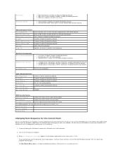
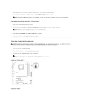
... Password Displays the status of the screen, press . Each device has a number next to boot from the CD drive so that you can run the Dell Diagnostics on (or restart) your computer and try again. Auto; 32 MB; 64 MB; 128 MB; 256 MB; 512 MB (Auto by default). ... Boot Device-Removable; Hard Drive; PCI Slot; Set the supervisor password through this feature to restart your computer to a USB device such as a floppy drive, memory key, or CD-RW drive. 1. Do Not Report (Report by default). When F2 = Setup, F12 = Boot Menu appears in the module bay. l USB ...
... Password Displays the status of the screen, press . Each device has a number next to boot from the CD drive so that you can run the Dell Diagnostics on (or restart) your computer and try again. Auto; 32 MB; 64 MB; 128 MB; 256 MB; 512 MB (Auto by default). ... Boot Device-Removable; Hard Drive; PCI Slot; Set the supervisor password through this feature to restart your computer to a USB device such as a floppy drive, memory key, or CD-RW drive. 1. Do Not Report (Report by default). When F2 = Setup, F12 = Boot Menu appears in the module bay. l USB ...
Service Manual
Page 40
... is bootable, check the device documentation. Follow the procedures in case you are booting to move through the list of device. Inspiron 535s/537s Inspiron 545s NOTE: Write down -arrow keys to a USB memory key, highlight USB Flash Device and press . Remove the computer cover (see Entering System Setup). 2. At the bottom of the... to access the menu. Enter system setup (see Removing the Computer Cover). 3. For additional safety best practices information, see the Regulatory Compliance Homepage at www.dell.com/regulatory_compliance. 1.
... is bootable, check the device documentation. Follow the procedures in case you are booting to move through the list of device. Inspiron 535s/537s Inspiron 545s NOTE: Write down -arrow keys to a USB memory key, highlight USB Flash Device and press . Remove the computer cover (see Entering System Setup). 2. At the bottom of the... to access the menu. Enter system setup (see Removing the Computer Cover). 3. For additional safety best practices information, see the Regulatory Compliance Homepage at www.dell.com/regulatory_compliance. 1.

Service Manual
Page 44
...after installing the new system board. 10. Remove the screws from the electrical outlet before removing the cover. Inspiron 535s/537s 1 screws (6) 2 system board Inspiron 545s/546s Remove the computer cover (see Removing the Processor). 8. WARNING: To guard against electrical shock, ...the memory modules (see Removing an Optical Drive). 6. Lift the system board up and out. For additional safety best practices information, see the Regulatory Compliance Homepage at www.dell.com/regulatory_compliance. Back to Contents Page System Board Dell™ Inspiron™ 535s/537s/545s...
...after installing the new system board. 10. Remove the screws from the electrical outlet before removing the cover. Inspiron 535s/537s 1 screws (6) 2 system board Inspiron 545s/546s Remove the computer cover (see Removing the Processor). 8. WARNING: To guard against electrical shock, ...the memory modules (see Removing an Optical Drive). 6. Lift the system board up and out. For additional safety best practices information, see the Regulatory Compliance Homepage at www.dell.com/regulatory_compliance. Back to Contents Page System Board Dell™ Inspiron™ 535s/537s/545s...

Service Manual
Page 46
...and Heat Sink Assembly). 6. Replace the processor fan and the heat sink assembly (see Replacing the Processor). 5. 2. Replace the memory modules into the memory sockets at the same locations from the system board. Replace the optical drive (see Replacing the Computer Cover). 11. Connect the ... system board to Contents Page Replace the computer cover (see Replacing an Optical Drive). 8. Replace the support bracket (see Replacing Memory). 7. Connect your computer and devices to an electrical outlet, and turn them (see Replacing the Support Bracket). 10. Replace any add-in...
...and Heat Sink Assembly). 6. Replace the processor fan and the heat sink assembly (see Replacing the Processor). 5. 2. Replace the memory modules into the memory sockets at the same locations from the system board. Replace the optical drive (see Replacing the Computer Cover). 11. Connect the ... system board to Contents Page Replace the computer cover (see Replacing an Optical Drive). 8. Replace the support bracket (see Replacing Memory). 7. Connect your computer and devices to an electrical outlet, and turn them (see Replacing the Support Bracket). 10. Replace any add-in...
Service Manual
Page 47
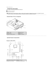
... System Board Components WARNING: Before working inside your computer, read the safety information that shipped with your computer. Back to Contents Page Technical Overview Dell™ Inspiron™ 535s/537s/545s/546s Service Manual Inside View of Your Computer 1 power supply 3 system board 5 media card reader (optional) 2 support bracket 4 optical drive 6 primary hard...
... System Board Components WARNING: Before working inside your computer, read the safety information that shipped with your computer. Back to Contents Page Technical Overview Dell™ Inspiron™ 535s/537s/545s/546s Service Manual Inside View of Your Computer 1 power supply 3 system board 5 media card reader (optional) 2 support bracket 4 optical drive 6 primary hard...
SETUP GUIDE
Page 5
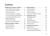
...the Power Cables to Your Display and Computer 11 Windows Vista® Setup 12 Connect to the Internet (Optional 12 Using Your Inspiron™ Desktop 16 Front View Features 16 Back View Features 18 Software Features 20 Solving Problems 23 Network Problems 23 Power Problems 25... Memory Problems 26 Lockups and Software Problems 27 Using Support Tools 30 Dell Support Center 30 Beep Codes 31 System Messages 32 Hardware Troubleshooter 34 Dell Diagnostics 34 System Recovery Options 37 System Restore 38 Dell Factory Image Restore 39 Operating ...
...the Power Cables to Your Display and Computer 11 Windows Vista® Setup 12 Connect to the Internet (Optional 12 Using Your Inspiron™ Desktop 16 Front View Features 16 Back View Features 18 Software Features 20 Solving Problems 23 Network Problems 23 Power Problems 25... Memory Problems 26 Lockups and Software Problems 27 Using Support Tools 30 Dell Support Center 30 Beep Codes 31 System Messages 32 Hardware Troubleshooter 34 Dell Diagnostics 34 System Recovery Options 37 System Restore 38 Dell Factory Image Restore 39 Operating ...

SETUP GUIDE
Page 19
Using Your Inspiron™ Desktop 5 Headphone connector - Connects to a microphone for voice or to USB devices such as memory keys, digital cameras, and MP3 players. Supports a Media Card Reader or an additional hard drive. 3 Power button - Connects to an audio cable for audio input. 8 ...
Using Your Inspiron™ Desktop 5 Headphone connector - Connects to a microphone for voice or to USB devices such as memory keys, digital cameras, and MP3 players. Supports a Media Card Reader or an additional hard drive. 3 Power button - Connects to an audio cable for audio input. 8 ...

SETUP GUIDE
Page 27
... strip is plugged into an electrical outlet and that the power supply diagnostic light on the back of the system is on the Dell Support website at support.dell.com). 25 If the power light is solid white and the computer is blinking amber - The computer is receiving electrical power, but a device... operation. You may not be connected or powered on the trackpad or a connected mouse, or press the power button to remove and then reinstall the memory modules (for information on removing and replacing memory modules, see the Service Manual on .
... strip is plugged into an electrical outlet and that the power supply diagnostic light on the back of the system is on the Dell Support website at support.dell.com). 25 If the power light is solid white and the computer is blinking amber - The computer is receiving electrical power, but a device... operation. You may not be connected or powered on the trackpad or a connected mouse, or press the power button to remove and then reinstall the memory modules (for information on removing and replacing memory modules, see the Service Manual on .

SETUP GUIDE
Page 28
... of interference are not using to see the Service Manual on the Dell Support website at support.dell.com) to ensure that hinders reception on the Dell Support website at support.dell.com). • Reseat the memory modules (see if that resolves the problem. • See the ...software documentation for minimum memory requirements. Solving Problems If you are : • Power, keyboard, and mouse extension cables. •...
... of interference are not using to see the Service Manual on the Dell Support website at support.dell.com) to ensure that hinders reception on the Dell Support website at support.dell.com). • Reseat the memory modules (see if that resolves the problem. • See the ...software documentation for minimum memory requirements. Solving Problems If you are : • Power, keyboard, and mouse extension cables. •...

SETUP GUIDE
Page 29
...is firmly connected to the computer and to ensure that is compatible with the memory. NOTE: Software usually includes installation instructions in its documentation or on the Dell Support website at support.dell.com) to the electrical outlet. End the program: 1. Click the program ... your computer is successfully communicating with your computer, see "Specifications" on page 52. • Run the Dell Diagnostics (see "Dell Diagnostics" on page 34). • Reseat the memory modules (see the Service Manual on CD. 27 Lockups and Software Problems If the computer does not start up...
...is firmly connected to the computer and to ensure that is compatible with the memory. NOTE: Software usually includes installation instructions in its documentation or on the Dell Support website at support.dell.com) to the electrical outlet. End the program: 1. Click the program ... your computer is successfully communicating with your computer, see "Specifications" on page 52. • Run the Dell Diagnostics (see "Dell Diagnostics" on page 34). • Reseat the memory modules (see the Service Manual on CD. 27 Lockups and Software Problems If the computer does not start up...
SETUP GUIDE
Page 33
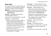
... the Dell Support website at support.dell.com). • Verify that the memory modules that you can identify a faulty module or reinstall the modules without an error. • If available, install memory modules of the same type in your computer. • If the problem persists contact Dell (see "Contacting Dell" on page 48). Seven beeps (Inspiron 535s...
... the Dell Support website at support.dell.com). • Verify that the memory modules that you can identify a faulty module or reinstall the modules without an error. • If available, install memory modules of the same type in your computer. • If the problem persists contact Dell (see "Contacting Dell" on page 48). Seven beeps (Inspiron 535s...
SETUP GUIDE
Page 52
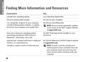
...found on your computer. find your computer with new or additional memory, or a new hard drive. upgrade your system model number. the Dell Technology Guide available on the Dell™ Support website at support.dell.com. the Drivers and Utilities disc. NOTE: In some countries,...: your operating system. the Service Manual on the Dell Support website at support.dell.com. the back of your computer may void your operating system, maintaining peripherals, RAID, Internet, Bluetooth®, networking, and e-mail. INSPIRON Finding More Information and Resources If you need to:...
...found on your computer. find your computer with new or additional memory, or a new hard drive. upgrade your system model number. the Dell Technology Guide available on the Dell™ Support website at support.dell.com. the Drivers and Utilities disc. NOTE: In some countries,...: your operating system. the Service Manual on the Dell Support website at support.dell.com. the back of your computer may void your operating system, maintaining peripherals, RAID, Internet, Bluetooth®, networking, and e-mail. INSPIRON Finding More Information and Resources If you need to:...


