Owners Manual
Page 5
18 Speakers 67 Removing the Speakers 67 Replacing the Speakers 69 19 Media Card Reader 71 Removing the Media Card Reader 71 Replacing the Media Card Reader 73 20 Daughter Board 75 Removing the Daughter Board 75 Replacing the Daughter Board 77 21 Mini-Card 79 Removing the Mini-Card 79 Replacing the Mini-Card 80 22 Flashing the BIOS 83 Contents | 5
18 Speakers 67 Removing the Speakers 67 Replacing the Speakers 69 19 Media Card Reader 71 Removing the Media Card Reader 71 Replacing the Media Card Reader 73 20 Daughter Board 75 Removing the Daughter Board 75 Replacing the Daughter Board 77 21 Mini-Card 79 Removing the Mini-Card 79 Replacing the Mini-Card 80 22 Flashing the BIOS 83 Contents | 5
Owners Manual
Page 51
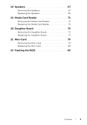
3 Disconnect the power-adapter port cable, fan cable, and speakers cable from the connectors on the system board. 4 Peel the tape that secures the display cable to the system board and then disconnect the display cable from the connector on the system board. 5 Lift the connector latch and pull the pull-tab to disconnect the Media Card Reader cable from the connector on the system board. . 9 8 7 6 5 1 2 3 4 1 power-adapter port cable 3 system-board assembly 5 connector latch 7 Media Card Reader cable 9 tape 2 fan cable 4 speakers cable 6 pull-tab 8 display cable System Board | 51
3 Disconnect the power-adapter port cable, fan cable, and speakers cable from the connectors on the system board. 4 Peel the tape that secures the display cable to the system board and then disconnect the display cable from the connector on the system board. 5 Lift the connector latch and pull the pull-tab to disconnect the Media Card Reader cable from the connector on the system board. . 9 8 7 6 5 1 2 3 4 1 power-adapter port cable 3 system-board assembly 5 connector latch 7 Media Card Reader cable 9 tape 2 fan cable 4 speakers cable 6 pull-tab 8 display cable System Board | 51
Owners Manual
Page 53
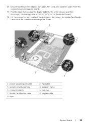
... on the system board and adhere the tape that secures the cable to the system board. 8 Connect the power-adapter port cable, fan cable, and speakers cable to the connectors on the system board. 9 Align the screw holes on the power-adapter port bracket with the screw holes on the computer...
... on the system board and adhere the tape that secures the cable to the system board. 8 Connect the power-adapter port cable, fan cable, and speakers cable to the connectors on the system board. 9 Align the screw holes on the power-adapter port bracket with the screw holes on the computer...
Owners Manual
Page 67
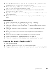
Speakers | 67 For additional safety best practices information, see the Regulatory Compliance Homepage at dell.com/regulatory_compliance. See "Removing the Memory Module(s)" on page 19. 4 Follow the instructions from step 1 to step 3 in "Removing the Hard Drive" on page 21... "Removing the Battery" on page 17. 3 Remove the memory module(s). See "Removing the Base Cover" on page 13. 2 Remove the base cover. 18 Speakers WARNING: Before working inside your computer, read the safety information that shipped with your computer and follow the steps in "Removing the System Board" on...
Speakers | 67 For additional safety best practices information, see the Regulatory Compliance Homepage at dell.com/regulatory_compliance. See "Removing the Memory Module(s)" on page 19. 4 Follow the instructions from step 1 to step 3 in "Removing the Hard Drive" on page 21... "Removing the Battery" on page 17. 3 Remove the memory module(s). See "Removing the Base Cover" on page 13. 2 Remove the base cover. 18 Speakers WARNING: Before working inside your computer, read the safety information that shipped with your computer and follow the steps in "Removing the System Board" on...
Owners Manual
Page 68
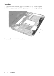
Procedure 1 Remove the screws that secure the speakers to the computer base. 2 Lift the speakers along with its cable away from the computer base. 2 1 1 screws (4) 2 speakers 68 | Speakers
Procedure 1 Remove the screws that secure the speakers to the computer base. 2 Lift the speakers along with its cable away from the computer base. 2 1 1 screws (4) 2 speakers 68 | Speakers
Owners Manual
Page 69
... the screw holes on the computer base and place the speakers on the computer base. 2 Replace the screws that secure the speakers to step 10 in "After Working Inside Your Computer" on page 9. Postrequisites 1 Follow the instructions from step 4 to step 6 in "Replacing the Hard Drive" on ... Optical Drive" on page 31. 3 Replace the keyboard. See "Replacing the Palm Rest" on page 26. 5 Follow the instructions from step 3 to the computer base. Speakers | 69
... the screw holes on the computer base and place the speakers on the computer base. 2 Replace the screws that secure the speakers to step 10 in "After Working Inside Your Computer" on page 9. Postrequisites 1 Follow the instructions from step 4 to step 6 in "Replacing the Hard Drive" on ... Optical Drive" on page 31. 3 Replace the keyboard. See "Replacing the Palm Rest" on page 26. 5 Follow the instructions from step 3 to the computer base. Speakers | 69
Owners Manual
Page 71
For additional safety best practices information, see the Regulatory Compliance Homepage at dell.com/regulatory_compliance. See "Removing the Palm Rest" on page 27. 8 Follow the instructions from step 1 to step 8 in "Before You Begin" on page 7. See "Removing the Speakers" on page 17. 3 Remove the memory module(s). See "Removing the Base Cover" on... your computer, read the safety information that shipped with your computer and follow the steps in "Removing the System Board" on page 49. 9 Remove the speakers.
For additional safety best practices information, see the Regulatory Compliance Homepage at dell.com/regulatory_compliance. See "Removing the Palm Rest" on page 27. 8 Follow the instructions from step 1 to step 8 in "Before You Begin" on page 7. See "Removing the Speakers" on page 17. 3 Remove the memory module(s). See "Removing the Base Cover" on... your computer, read the safety information that shipped with your computer and follow the steps in "Removing the System Board" on page 49. 9 Remove the speakers.
Owners Manual
Page 73
... "Replacing the Hard Drive" on page 23. 6 Replace the memory module(s). See "Replacing the Base Cover" on page 31. 3 Replace the keyboard. See "Replacing the Speakers" on page 69. 1 Follow the instructions from step 4 to the computer base. Postrequisites 1 Replace the...
... "Replacing the Hard Drive" on page 23. 6 Replace the memory module(s). See "Replacing the Base Cover" on page 31. 3 Replace the keyboard. See "Replacing the Speakers" on page 69. 1 Follow the instructions from step 4 to the computer base. Postrequisites 1 Replace the...
Me and My Dell
Page 5
Video Cards 44 TV Tuners 45 Speakers 46 Webcam 46 Enabling a Webcam 47 Dell Webcam Manager 47 ExpressCards 48 Communication Devices 49 Setting Up Your Laptop 55 Setting Up Your Desktop 57 Internet 59 Setting Up a Wired Internet Connection ...
Video Cards 44 TV Tuners 45 Speakers 46 Webcam 46 Enabling a Webcam 47 Dell Webcam Manager 47 ExpressCards 48 Communication Devices 49 Setting Up Your Laptop 55 Setting Up Your Desktop 57 Internet 59 Setting Up a Wired Internet Connection ...
Me and My Dell
Page 46
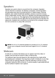
... (1) indicates the subwoofer. A camera quality is a device that allows you to your computer using USB connector. Speakers Speakers are generally identified as 2, 2.1, 5.1, 7.1, and so on. Speakers are used only for producing error or failure beeps. External webcams connect to capture real-time video or images, ... or you made while purchasing your computer sound card must support 5.1 or 7.1 channel audio. Speakers can also be internal or external. The webcam type may vary based on . Speakers are generally used to listen to buy an external webcam. You may need to sound from ...
... (1) indicates the subwoofer. A camera quality is a device that allows you to your computer using USB connector. Speakers Speakers are generally identified as 2, 2.1, 5.1, 7.1, and so on. Speakers are used only for producing error or failure beeps. External webcams connect to capture real-time video or images, ... or you made while purchasing your computer sound card must support 5.1 or 7.1 channel audio. Speakers can also be internal or external. The webcam type may vary based on . Speakers are generally used to listen to buy an external webcam. You may need to sound from ...

Me and My Dell
Page 66
Audio Setting Up 5.1 Audio 5.1 audio is most effective when the speakers are placed as shown in the following figure: 66 Audio Connect the other end of the power cable to the display's three-prong power strip or wall outlet. 7. Turn on your computer, and then turn on your display. 6.
Audio Setting Up 5.1 Audio 5.1 audio is most effective when the speakers are placed as shown in the following figure: 66 Audio Connect the other end of the power cable to the display's three-prong power strip or wall outlet. 7. Turn on your computer, and then turn on your display. 6.
Me and My Dell
Page 67
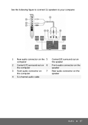
See the following figure to connect 5.1 speakers to your computer. 1 Rear audio connector on the 5 computer 2 Center/LFE surround out on 6 the computer 3 Front audio connector on 7 the computer 4 5.1 channel audio cable Center/LFE surround out on the speaker Front audio connector on the speaker Rear audio connector on the speaker Audio 67
See the following figure to connect 5.1 speakers to your computer. 1 Rear audio connector on the 5 computer 2 Center/LFE surround out on 6 the computer 3 Front audio connector on 7 the computer 4 5.1 channel audio cable Center/LFE surround out on the speaker Front audio connector on the speaker Rear audio connector on the speaker Audio 67

Me and My Dell
Page 68
... 3. You should hear a tone from every speaker. 4. Follow the instructions on the screen. To set up your computer sound, see the knowledge base article 266424 at support.dell.com. Setting Up 7.1 Audio 7.1 audio is most effective when the speakers are placed as shown in the following figure:... See the following figure to connect 7.1 speakers to your computer: 68 Audio Click Start Control ...
... 3. You should hear a tone from every speaker. 4. Follow the instructions on the screen. To set up your computer sound, see the knowledge base article 266424 at support.dell.com. Setting Up 7.1 Audio 7.1 audio is most effective when the speakers are placed as shown in the following figure:... See the following figure to connect 7.1 speakers to your computer: 68 Audio Click Start Control ...
Me and My Dell
Page 69
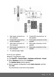
... and Sound→ Sound. 2. Select Speakers and then click Configure. Audio 69 Select a speaker configuration under Audio channels: and then click Test. 1 Rear audio connector on 6 Center/LFE surround out on the computer the speaker 2 Center/LFE surround out 7 Front ...on the computer speaker 3 Side audio connector on 8 Rear audio connector on the the computer speaker 4 Front audio connector on 9 Side audio connector on the the computer speaker 5 7.1 channel audio cable To set up your speakers: Windows 7 and Windows Vista 1. The Speaker Setup window appears....
... and Sound→ Sound. 2. Select Speakers and then click Configure. Audio 69 Select a speaker configuration under Audio channels: and then click Test. 1 Rear audio connector on 6 Center/LFE surround out on the computer the speaker 2 Center/LFE surround out 7 Front ...on the computer speaker 3 Side audio connector on 8 Rear audio connector on the the computer speaker 4 Front audio connector on 9 Side audio connector on the the computer speaker 5 7.1 channel audio cable To set up your speakers: Windows 7 and Windows Vista 1. The Speaker Setup window appears....
Me and My Dell
Page 89
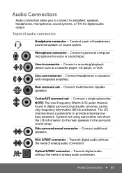
...audio conversion. Audio Connectors Audio connectors allow you to connect to amplifiers, speakers, headphones, microphones, sound systems, or TVs for voice or sound input. Types of headphones, powered speaker, or sound system. Microphone connector - Center/LFE surround out - .... Line-out connector - Audio Connectors 89 Connect a personal computer microphone for digital audio output. Connect headphones or speakers with integrated amplifiers. Transmit digital audio without the need of analog audio conversion. Line-in connector - The LFE channel drives a ...
...audio conversion. Audio Connectors Audio connectors allow you to connect to amplifiers, speakers, headphones, microphones, sound systems, or TVs for voice or sound input. Types of headphones, powered speaker, or sound system. Microphone connector - Center/LFE surround out - .... Line-out connector - Audio Connectors 89 Connect a personal computer microphone for digital audio output. Connect headphones or speakers with integrated amplifiers. Transmit digital audio without the need of analog audio conversion. Line-in connector - The LFE channel drives a ...
Me and My Dell
Page 90
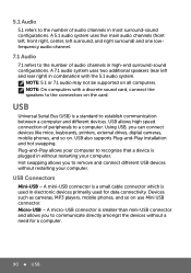
... your computer. A mini-USB connector is a small cable connector which is plugged in combination with a discrete sound card, connect the speakers to the connectors on . A 5.1 audio system uses five main audio channels (front left, front right, center, left and rear right...61557; USB A micro-USB connector is a standard to establish communication between a computer and different devices. A 7.1 audio system uses two additional speakers (rear left surround, and right surround) and one lowfrequency audio channel. 7.1 Audio 7.1 refers to the number of audio channels in most surround...
... your computer. A mini-USB connector is a small cable connector which is plugged in combination with a discrete sound card, connect the speakers to the connectors on . A 5.1 audio system uses five main audio channels (front left, front right, center, left and rear right...61557; USB A micro-USB connector is a standard to establish communication between a computer and different devices. A 7.1 audio system uses two additional speakers (rear left surround, and right surround) and one lowfrequency audio channel. 7.1 Audio 7.1 refers to the number of audio channels in most surround...


