
Owners Manual
Page 4
10 Palm Rest 27 Removing the Palm Rest 27 Replacing the Palm Rest 31 11 Power-Adapter Port 33 Removing the Power-Adapter Port 33 Replacing the Power-Adapter Port 34 12 Display Assembly 35 Removing the Display Assembly 35 Replacing the Display Assembly 37 Removing the Display Bezel 37 Replacing the Display Bezel...
10 Palm Rest 27 Removing the Palm Rest 27 Replacing the Palm Rest 31 11 Power-Adapter Port 33 Removing the Power-Adapter Port 33 Replacing the Power-Adapter Port 34 12 Display Assembly 35 Removing the Display Assembly 35 Replacing the Display Assembly 37 Removing the Display Bezel 37 Replacing the Display Bezel...
Owners Manual
Page 8
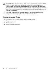
... • Plastic scribe • Small flat-blade screwdriver 8 | Before You Begin Some cables have connectors with locking tabs or thumb-screws that the connectors and ports are correctly oriented and aligned. When connecting cables, ensure that you disconnect a cable, pull on its connector or on its pull-tab, not on the...
... • Plastic scribe • Small flat-blade screwdriver 8 | Before You Begin Some cables have connectors with locking tabs or thumb-screws that the connectors and ports are correctly oriented and aligned. When connecting cables, ensure that you disconnect a cable, pull on its connector or on its pull-tab, not on the...

Owners Manual
Page 33
... information that secure the power-adapter port bracket to the computer base. 2 Lift the power-adapter port bracket off the computer base. 1 2 1 screws (2) 2 power-adapter port bracket Power-Adapter Port | 33 For additional safety best practices information, see the Regulatory Compliance Homepage at dell.com/regulatory_compliance. 11 Power-Adapter Port WARNING: Before working inside your computer...
... information that secure the power-adapter port bracket to the computer base. 2 Lift the power-adapter port bracket off the computer base. 1 2 1 screws (2) 2 power-adapter port bracket Power-Adapter Port | 33 For additional safety best practices information, see the Regulatory Compliance Homepage at dell.com/regulatory_compliance. 11 Power-Adapter Port WARNING: Before working inside your computer...
Owners Manual
Page 34
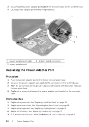
... the instructions in the slot on the computer base. 2 Connect the power-adapter port cable to the connector on the system board. 3 Align the screw holes on the power-adapter port bracket with the screw holes on the computer base. 4 Replace the screws that ...keyboard. 3 Disconnect the power-adapter port cable from the connector on the system board. 4 Lift the power-adapter port off the computer base. 1 2 3 1 power-adapter port cable 3 power-adapter port 2 system-board connector Replacing the Power-Adapter Port Procedure 1 Place the power-adapter port in "After Working Inside Your Computer...
... the instructions in the slot on the computer base. 2 Connect the power-adapter port cable to the connector on the system board. 3 Align the screw holes on the power-adapter port bracket with the screw holes on the computer base. 4 Replace the screws that ...keyboard. 3 Disconnect the power-adapter port cable from the connector on the system board. 4 Lift the power-adapter port off the computer base. 1 2 3 1 power-adapter port cable 3 power-adapter port 2 system-board connector Replacing the Power-Adapter Port Procedure 1 Place the power-adapter port in "After Working Inside Your Computer...

Owners Manual
Page 50
You must enter the Service Tag in the system board. Procedure NOTE: Your computer's Service Tag is stored in the BIOS after you replace the system-board assembly. 1 Remove the screws that you can reconnect them correctly after you replace the system-board assembly. NOTE: Before disconnecting the cables from the system board, note the location of the connectors so that secure the power-adapter port bracket to the computer base. 2 Lift the power-adapter port bracket off the computer base. 1 2 1 screws (2) 2 power-adapter port bracket 50 | System Board
You must enter the Service Tag in the system board. Procedure NOTE: Your computer's Service Tag is stored in the BIOS after you replace the system-board assembly. 1 Remove the screws that you can reconnect them correctly after you replace the system-board assembly. NOTE: Before disconnecting the cables from the system board, note the location of the connectors so that secure the power-adapter port bracket to the computer base. 2 Lift the power-adapter port bracket off the computer base. 1 2 1 screws (2) 2 power-adapter port bracket 50 | System Board
Owners Manual
Page 51
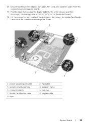
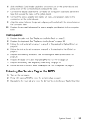
3 Disconnect the power-adapter port cable, fan cable, and speakers cable from the connectors on the system board. 4 Peel the tape that secures the display cable to the system board and then disconnect the display cable from the connector on the system board. 5 Lift the connector latch and pull the pull-tab to disconnect the Media Card Reader cable from the connector on the system board. . 9 8 7 6 5 1 2 3 4 1 power-adapter port cable 3 system-board assembly 5 connector latch 7 Media Card Reader cable 9 tape 2 fan cable 4 speakers cable 6 pull-tab 8 display cable System Board | 51
3 Disconnect the power-adapter port cable, fan cable, and speakers cable from the connectors on the system board. 4 Peel the tape that secures the display cable to the system board and then disconnect the display cable from the connector on the system board. 5 Lift the connector latch and pull the pull-tab to disconnect the Media Card Reader cable from the connector on the system board. . 9 8 7 6 5 1 2 3 4 1 power-adapter port cable 3 system-board assembly 5 connector latch 7 Media Card Reader cable 9 tape 2 fan cable 4 speakers cable 6 pull-tab 8 display cable System Board | 51
Owners Manual
Page 53
... display cable to the connector on the system board and adhere the tape that secure the power-adapter port bracket to the main tab and enter the Service Tag in the Service Tag Setting field. See "Replacing...the screws that secures the cable to the system board. 8 Connect the power-adapter port cable, fan cable, and speakers cable to the connectors on the system board. 9 Align the screw holes ...on the power-adapter port bracket with the screw holes on page 23. 5 Replace the memory module(s). Entering the Service Tag...
... display cable to the connector on the system board and adhere the tape that secure the power-adapter port bracket to the main tab and enter the Service Tag in the Service Tag Setting field. See "Replacing...the screws that secures the cable to the system board. 8 Connect the power-adapter port cable, fan cable, and speakers cable to the connectors on the system board. 9 Align the screw holes ...on the power-adapter port bracket with the screw holes on page 23. 5 Replace the memory module(s). Entering the Service Tag...
Me and My Dell
Page 35
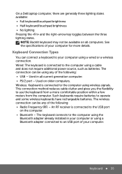
...your computer. The wireless connection can connect a keyboard to an USB port of the following : • Radio Frequency (RF) - The keyboard connects to the computer using a wired or a wireless connection. On a Dell laptop computer, there are generally three lighting states available: • Full... clutter and gives you the flexibility to the computer using wireless signals. Used on all current generation computer. • PS/2 port - An RF receiver is connected to operate and some wireless keyboards have rechargeable batteries. Keyboard 35 Wired: The keyboard...
...your computer. The wireless connection can connect a keyboard to an USB port of the following : • Radio Frequency (RF) - The keyboard connects to the computer using a wired or a wireless connection. On a Dell laptop computer, there are generally three lighting states available: • Full... clutter and gives you the flexibility to the computer using wireless signals. Used on all current generation computer. • PS/2 port - An RF receiver is connected to operate and some wireless keyboards have rechargeable batteries. Keyboard 35 Wired: The keyboard...

Me and My Dell
Page 57
Connect the display to the USB connectors. Setting Up Your Desktop 57 NOTE: Depending on your computer model, USB ports may also be present on your computer. Setting Up Your Desktop 1. Connect the USB keyboard and mouse to the appropriate display connector on the front panel of your computer (see Setting Up Your Display). 2.
Connect the display to the USB connectors. Setting Up Your Desktop 57 NOTE: Depending on your computer model, USB ports may also be present on your computer. Setting Up Your Desktop 1. Connect the USB keyboard and mouse to the appropriate display connector on the front panel of your computer (see Setting Up Your Display). 2.
Me and My Dell
Page 65
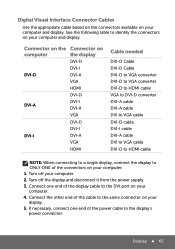
If necessary, connect one end of the cable to the DVI port on your computer. 4. Turn off the display and disconnect it from the power supply. 3. Turn off your computer and display. Display 65 Connect the ...
If necessary, connect one end of the cable to the DVI port on your computer. 4. Turn off the display and disconnect it from the power supply. 3. Turn off your computer and display. Display 65 Connect the ...

Me and My Dell
Page 87
Ports and Connectors
Ports and Connectors
Me and My Dell
Page 91
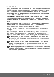
... done using the system setup. In such cases, turn off your computer while charging a USB device, the device stops charging. Debug Port - Legacy USB standard supporting data transfer speeds up to charge the device. To continue charging, disconnect the USB device and connect it provides... 1.1. USB PowerShare - You can configure this limit using a USB optical or Flash drive. Referred to run the USB 3.0 ports in sleep state. The debug port enables a user to as SuperSpeed USB, USB 3.0 is in USB 2.0 mode temporarily for multimedia and storage applications. icon indicates...
... done using the system setup. In such cases, turn off your computer while charging a USB device, the device stops charging. Debug Port - Legacy USB standard supporting data transfer speeds up to charge the device. To continue charging, disconnect the USB device and connect it provides... 1.1. USB PowerShare - You can configure this limit using a USB optical or Flash drive. Referred to run the USB 3.0 ports in sleep state. The debug port enables a user to as SuperSpeed USB, USB 3.0 is in USB 2.0 mode temporarily for multimedia and storage applications. icon indicates...
Me and My Dell
Page 94
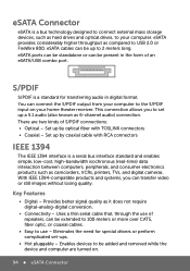
...does not require digital‑analog-digital conversion. • Connectivity - Eliminates the need for transferring audio in the form of an eSATA/USB combo port. eSATA cables can be extended to 100 meters or more over CAT5, fiber optic, or coaxial cables. • Easy to be up by... cable that, through the use - With IEEE 1394-compatible products and systems, you to the S/PDIF input on . 94 eSATA Connector eSATA ports can be standalone or can be added and removed while the device and computer are two kinds of repeaters, can be present in digital format...
...does not require digital‑analog-digital conversion. • Connectivity - Eliminates the need for transferring audio in the form of an eSATA/USB combo port. eSATA cables can be extended to 100 meters or more over CAT5, fiber optic, or coaxial cables. • Easy to be up by... cable that, through the use - With IEEE 1394-compatible products and systems, you to the S/PDIF input on . 94 eSATA Connector eSATA ports can be standalone or can be added and removed while the device and computer are two kinds of repeaters, can be present in digital format...
Me and My Dell
Page 103
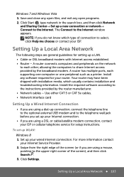
... optional external USB modem and to the Internet. The Connect to share Internet access provided by the router manufacturer. • Network cables - A router has multiple ports, each other, allowing the computers to the Internet window appears. Use either CAT 5 or CAT 5e cables. • Network interface card Setting Up a Wired Internet...
... optional external USB modem and to the Internet. The Connect to share Internet access provided by the router manufacturer. • Network cables - A router has multiple ports, each other, allowing the computers to the Internet window appears. Use either CAT 5 or CAT 5e cables. • Network interface card Setting Up a Wired Internet...

Me and My Dell
Page 167
... hard disk, and then turns off . the computer immediately stops what it is doing and is a power-saving state that connects two computers through USB ports. • Network - Power Management 167 Sleep is ready to start again when you want to the various components. You need a USB flash drive or...
... hard disk, and then turns off . the computer immediately stops what it is doing and is a power-saving state that connects two computers through USB ports. • Network - Power Management 167 Sleep is ready to start again when you want to the various components. You need a USB flash drive or...


