
Hardware Reference
Page 5
... Cards (LCCs 1-8 Disk modules 1-9 Power supply/system cooling modules 1-11 Chapter 2 Installing a DAE2P/DAE3P Requirements 2-2 Installing a disk enclosure in a cabinet 2-3 Setting up an installed disk enclosure 2-4 Connecting AC Power 2-5 Setting the enclosure address 2-10 Connecting the DAE2P/DAE3P to... the back end bus 2-12 Binding disk modules into RAID groups 2-15 Chapter 3 Servicing a DAE2P/DAE3P Monitoring disk enclosure status 3-2 Handling FRUs 3-6 Replacing or adding a...
... Cards (LCCs 1-8 Disk modules 1-9 Power supply/system cooling modules 1-11 Chapter 2 Installing a DAE2P/DAE3P Requirements 2-2 Installing a disk enclosure in a cabinet 2-3 Setting up an installed disk enclosure 2-4 Connecting AC Power 2-5 Setting the enclosure address 2-10 Connecting the DAE2P/DAE3P to... the back end bus 2-12 Binding disk modules into RAID groups 2-15 Chapter 3 Servicing a DAE2P/DAE3P Monitoring disk enclosure status 3-2 Handling FRUs 3-6 Replacing or adding a...

Hardware Reference
Page 7
...locking the front bezel 3-16 3-11 Removing a copper cable from an LCC 3-17 3-12 Removing an LCC 3-18 DAE2P/DAE3P Hardware Reference vii Figures 1-1 DAE2P/DAE3P 1-2 1-2 DAE2P/DAE3P front LED display 1-4 1-3 DAE2P/DAE3P rear components 1-5 1-4 Disk enclosure rear view - LEDs and connectors... bus and address indicators 1-6 1-6 Disk enclosure front bezel 1-7 1-7 LCC connectors and status LEDs 1-8 1-8 Disk modules 1-10 1-9 Power/cooling module LEDs 1-12 2-1 Plugging in the AC line cords 2-5 2-2 Connecting DAE2P power cords (CX300/CX500 storage system) ........ 2-7 2-3 Connecting DAE3P ...
...locking the front bezel 3-16 3-11 Removing a copper cable from an LCC 3-17 3-12 Removing an LCC 3-18 DAE2P/DAE3P Hardware Reference vii Figures 1-1 DAE2P/DAE3P 1-2 1-2 DAE2P/DAE3P front LED display 1-4 1-3 DAE2P/DAE3P rear components 1-5 1-4 Disk enclosure rear view - LEDs and connectors... bus and address indicators 1-6 1-6 Disk enclosure front bezel 1-7 1-7 LCC connectors and status LEDs 1-8 1-8 Disk modules 1-10 1-9 Power/cooling module LEDs 1-12 2-1 Plugging in the AC line cords 2-5 2-2 Connecting DAE2P power cords (CX300/CX500 storage system) ........ 2-7 2-3 Connecting DAE3P ...

Hardware Reference
Page 8
Contents 3-13 Installing an LCC 3-18 3-14 Reconnecting a copper cable to an LCC 3-19 3-15 Unplugging the AC power cord 3-20 3-16 Removing a power/cooling module 3-21 3-17 Installing a power/cooling module 3-21 3-18 Plugging in the power cord 3-22 viii DAE2P/DAE3P Hardware Reference
Contents 3-13 Installing an LCC 3-18 3-14 Reconnecting a copper cable to an LCC 3-19 3-15 Unplugging the AC power cord 3-20 3-16 Removing a power/cooling module 3-21 3-17 Installing a power/cooling module 3-21 3-18 Plugging in the power cord 3-22 viii DAE2P/DAE3P Hardware Reference

Hardware Reference
Page 17
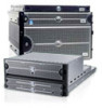
Invisible Body Tag 1 About DAE2P and DAE3P disk enclosures Topics in this chapter include: ◆ Introduction 1-2 ◆ Link Control Cards (LCCs 1-8 ◆ Disk modules 1-9 ◆ Power supply/system cooling modules 1-11 About DAE2P and DAE3P disk enclosures 1-1
Invisible Body Tag 1 About DAE2P and DAE3P disk enclosures Topics in this chapter include: ◆ Introduction 1-2 ◆ Link Control Cards (LCCs 1-8 ◆ Disk modules 1-9 ◆ Power supply/system cooling modules 1-11 About DAE2P and DAE3P disk enclosures 1-1

Hardware Reference
Page 19
... the four system cooling blowers must be running with a midplane and front bezel ◆ Two link control cards (LCCs) ◆ As many as shown in one operating power supply and a single functional LCC. The DAE2P and DAE3P are externally identical except for two identical components, the components are packaged together into a single field...
... the four system cooling blowers must be running with a midplane and front bezel ◆ Two link control cards (LCCs) ◆ As many as shown in one operating power supply and a single functional LCC. The DAE2P and DAE3P are externally identical except for two identical components, the components are packaged together into a single field...

Hardware Reference
Page 21
...in CLARiiON) Expansion (Out) Primary (In) ! !! +- The storage processor initializes bus ID when the operating system loads. About DAE2P and DAE3P disk enclosures Power/Cooling Module B Link Control Card B EXP PRI PRI # PRI EXP EXP ! !! ! !! # EXP PRI Power/Cooling Module A Figure... 1-3 DAE2P/DAE3P rear components Link Control Card A EMC3232 SPS (Not used in Figure 1-5, an enclosure address (EA) indicator is located on each LCC. (The EA is sometimes referred to as an enclosure ID.) Each link control card...
...in CLARiiON) Expansion (Out) Primary (In) ! !! +- The storage processor initializes bus ID when the operating system loads. About DAE2P and DAE3P disk enclosures Power/Cooling Module B Link Control Card B EXP PRI PRI # PRI EXP EXP ! !! ! !! # EXP PRI Power/Cooling Module A Figure... 1-3 DAE2P/DAE3P rear components Link Control Card A EMC3232 SPS (Not used in Figure 1-5, an enclosure address (EA) indicator is located on each LCC. (The EA is sometimes referred to as an enclosure ID.) Each link control card...

Hardware Reference
Page 22
... "Monitoring disk enclosure status" section of Chapter 3. plug directly into the midplane. You must remove the bezel 1-6 DAE2P/DAE3P Hardware Reference enclosure 1 contains modules 15-29; Midplane A midplane between the disk modules and the LCC and power/cooling modules distributes power and signals to change EA) 3 2 1 0 # 7 6 5 4 7 6 5 4 ! !! EXP PRI ! Front bezel The front...
... "Monitoring disk enclosure status" section of Chapter 3. plug directly into the midplane. You must remove the bezel 1-6 DAE2P/DAE3P Hardware Reference enclosure 1 contains modules 15-29; Midplane A midplane between the disk modules and the LCC and power/cooling modules distributes power and signals to change EA) 3 2 1 0 # 7 6 5 4 7 6 5 4 ! !! EXP PRI ! Front bezel The front...

Hardware Reference
Page 24
...the drives in its enclosure in a point-to the system's storage processors, the switch passes input 1-8 DAE2P/DAE3P Hardware Reference Internally, each DAE2P/DAE3P LCC uses FC_AL protocols to other Fibre Channel devices (processor enclosures, or other DAEs) with twin-axial copper cables...the drive being accessed; The LCCs in DAE2P enclosures, and DAE3Ps operating at four gigabits. About DAE2P and DAE3P disk enclosures Link Control Cards (LCCs) An LCC supports and controls one Fibre Channel bus and monitors the DAE2P/DAE3P. The LCC independently receives and electrically terminates ...
...the drives in its enclosure in a point-to the system's storage processors, the switch passes input 1-8 DAE2P/DAE3P Hardware Reference Internally, each DAE2P/DAE3P LCC uses FC_AL protocols to other Fibre Channel devices (processor enclosures, or other DAEs) with twin-axial copper cables...the drive being accessed; The LCCs in DAE2P enclosures, and DAE3Ps operating at four gigabits. About DAE2P and DAE3P disk enclosures Link Control Cards (LCCs) An LCC supports and controls one Fibre Channel bus and monitors the DAE2P/DAE3P. The LCC independently receives and electrically terminates ...

Hardware Reference
Page 25
...in "Monitoring disk enclosure status," in Chapter 3. DAE2P enclosures do not communicate with DAE2P/DAE3Ps within a DAE2P or DAE3P. (DAE3P SATA disks will not work in a carrier. Captive screws on each other. You can add or replace an LCC while the disk enclosure is powered up . With...provides a bridge between module types by their cabling; LCC firmware also controls the LCC port bypass circuits and the disk-module status lights. DAE2P and DAE3P disk modules support dual-port FC-AL interconnects through the two LCCs and their different latch and handle mechanisms and by labels...
...in "Monitoring disk enclosure status," in Chapter 3. DAE2P enclosures do not communicate with DAE2P/DAE3Ps within a DAE2P or DAE3P. (DAE3P SATA disks will not work in a carrier. Captive screws on each other. You can add or replace an LCC while the disk enclosure is powered up . With...provides a bridge between module types by their cabling; LCC firmware also controls the LCC port bypass circuits and the disk-module status lights. DAE2P and DAE3P disk modules support dual-port FC-AL interconnects through the two LCCs and their different latch and handle mechanisms and by labels...

Hardware Reference
Page 27
... Drive modules are located above and below the LCCs. Refer to the supply; Power supply/system cooling modules The power supply/system cooling (power/cooling) modules are extremely sensitive electronic components. Each supply supports a fully configured DAE2P/DAE3P and shares load currents with its own ...other supply. Each power/cooling module has three visible status lights. The latch holds the disk module in each module) fail, the DAE2P/DAE3P will speed up . The units integrate independent power supply and dual-blower cooling assemblies into the carrier. the center LED indicates...
... Drive modules are located above and below the LCCs. Refer to the supply; Power supply/system cooling modules The power supply/system cooling (power/cooling) modules are extremely sensitive electronic components. Each supply supports a fully configured DAE2P/DAE3P and shares load currents with its own ...other supply. Each power/cooling module has three visible status lights. The latch holds the disk module in each module) fail, the DAE2P/DAE3P will speed up . The units integrate independent power supply and dual-blower cooling assemblies into the carrier. the center LED indicates...

Hardware Reference
Page 31
... rails that has dual power distribution units, one Fibre Channel (FC) loop should interconnect all and only the LCC As, and the other Fibre Channel loop should be installed into a rack without a mechanical lift and/or help from the host or...Field Installation Guide is , one on your support website. Also, the cabinet should maintain LCC consistency; that is available on each side. Warnings and recommendations The cabinet in a cabinet 2-3 Installing a DAE2P/DAE3P Interconnections between disk enclosures should have a full earth ground to provide reliable grounding. To...
... rails that has dual power distribution units, one Fibre Channel (FC) loop should interconnect all and only the LCC As, and the other Fibre Channel loop should be installed into a rack without a mechanical lift and/or help from the host or...Field Installation Guide is , one on your support website. Also, the cabinet should maintain LCC consistency; that is available on each side. Warnings and recommendations The cabinet in a cabinet 2-3 Installing a DAE2P/DAE3P Interconnections between disk enclosures should have a full earth ground to provide reliable grounding. To...

Hardware Reference
Page 34
... (Enclosure Address 0, bus 0). 3. For example, connect power/cooling module A to the right pdu, and power/cooling module B to an appropriate power source. Connect the DAE2P/DAE3P power cords to the pdu on the left (facing the rear of the cabinet). Do not power up a disk enclosure without at least one... LCC installed. For proper cooling and normal operation, make sure all the disk module slots in a cabinet. For high availability, always connect each disk enclosure ...
... (Enclosure Address 0, bus 0). 3. For example, connect power/cooling module A to the right pdu, and power/cooling module B to an appropriate power source. Connect the DAE2P/DAE3P power cords to the pdu on the left (facing the rear of the cabinet). Do not power up a disk enclosure without at least one... LCC installed. For proper cooling and normal operation, make sure all the disk module slots in a cabinet. For high availability, always connect each disk enclosure ...

Hardware Reference
Page 39
... or when the drive is not part of a back-end bus; Set the enclosure address to the selection button; The second LCC will automatically change to the new value. 1 Bus ID 2 3 Enclosure Address EA Selection (Press here to change the EA...the enclosure address (EA) !! To avoid losing data, you cannot change EA) 3 2 1 0 # 0 7 6 5 4 7 6 5 4 ! !! each button press increments the value. Installing a DAE2P/DAE3P ! EMC3210 Setting the enclosure address 2-11 The address is connected. 1. you must set the EA on and the enclosure is reset. You can set...
... or when the drive is not part of a back-end bus; Set the enclosure address to the selection button; The second LCC will automatically change to the new value. 1 Bus ID 2 3 Enclosure Address EA Selection (Press here to change the EA...the enclosure address (EA) !! To avoid losing data, you cannot change EA) 3 2 1 0 # 0 7 6 5 4 7 6 5 4 ! !! each button press increments the value. Installing a DAE2P/DAE3P ! EMC3210 Setting the enclosure address 2-11 The address is connected. 1. you must set the EA on and the enclosure is reset. You can set...

Hardware Reference
Page 40
... disk enclosures, cable them as shown in Figures 2-6 and Figure 2-7. 2-12 DAE2P/DAE3P Hardware Reference use HSSDC2-HSSDC2 cables to connect DAE2Ps and DAE3Ps, and use SFP-HSSDC2 cables to connect to LCC A. Attach the copper cable from the EXP connector to orient the HSSDC2 connectors...Enclosure ! !! # EXP ! !! The connector thumb clip faces up when connecting to LCC B, and down when connecting to a CX3-series SPE. ! Installing a DAE2P/DAE3P Connecting the DAE2P/DAE3P to the back end bus Attach your DAE2P/DAE3P to connect a CX-series DPE2 , DAE2, or SPE; Use HSSDC-HSSDC2 ...
... disk enclosures, cable them as shown in Figures 2-6 and Figure 2-7. 2-12 DAE2P/DAE3P Hardware Reference use HSSDC2-HSSDC2 cables to connect DAE2Ps and DAE3Ps, and use SFP-HSSDC2 cables to connect to LCC A. Attach the copper cable from the EXP connector to orient the HSSDC2 connectors...Enclosure ! !! # EXP ! !! The connector thumb clip faces up when connecting to LCC B, and down when connecting to a CX3-series SPE. ! Installing a DAE2P/DAE3P Connecting the DAE2P/DAE3P to the back end bus Attach your DAE2P/DAE3P to connect a CX-series DPE2 , DAE2, or SPE; Use HSSDC-HSSDC2 ...

Hardware Reference
Page 41
... chapter show configurations with a mix of the eight devices supports two completely redundant loops. Each of DAE2 and DAE2P/DAE3P enclosures follow the same EA, bus balancing, and cabling conventions whenever possible and practical. LCC B B A B A B A B Bus 1 A B A B A B A Bus 0 B A SPS B !! !! !! !! !! !! !! !! # EA3/Bus ... EA1/Bus 0 EXP PRI PRI ! # PRI EXP EXP # ! two Fibre Channel buses Connecting the DAE2P/DAE3P to -Primary chain. LCC A Bus 1 Bus 0 SPS A Figure 2-6 EMC3412 Cabling disk enclosures together - The configuration example in ...
... chapter show configurations with a mix of the eight devices supports two completely redundant loops. Each of DAE2 and DAE2P/DAE3P enclosures follow the same EA, bus balancing, and cabling conventions whenever possible and practical. LCC B B A B A B A B Bus 1 A B A B A B A Bus 0 B A SPS B !! !! !! !! !! !! !! !! # EA3/Bus ... EA1/Bus 0 EXP PRI PRI ! # PRI EXP EXP # ! two Fibre Channel buses Connecting the DAE2P/DAE3P to -Primary chain. LCC A Bus 1 Bus 0 SPS A Figure 2-6 EMC3412 Cabling disk enclosures together - The configuration example in ...

Hardware Reference
Page 42
... ! # PRI EXP EXP LCC A ! EXP PRI !! EA1/Bus 2 EXP PRI ! EA1/Bus 0 EXP PRI ! Installing a DAE2P/DAE3P Figure 2-7 shows a more complicated configuration with ten DAE3Ps and four Fibre Channel buses. EXP PRI !! four Fibre Channel buses 2-14 DAE2P/DAE3P Hardware Reference Bus 3 !! Bus 2 ! Bus 1 ! SPS B SPS A EMC3410 Figure 2-7 Cabling DAE2Ps/DAE3Ps together - PRI EXP...
... ! # PRI EXP EXP LCC A ! EXP PRI !! EA1/Bus 2 EXP PRI ! EA1/Bus 0 EXP PRI ! Installing a DAE2P/DAE3P Figure 2-7 shows a more complicated configuration with ten DAE3Ps and four Fibre Channel buses. EXP PRI !! four Fibre Channel buses 2-14 DAE2P/DAE3P Hardware Reference Bus 3 !! Bus 2 ! Bus 1 ! SPS B SPS A EMC3410 Figure 2-7 Cabling DAE2Ps/DAE3Ps together - PRI EXP...

Hardware Reference
Page 45
Topics are: ◆ Monitoring disk enclosure status 3-2 ◆ Handling FRUs 3-6 ◆ Replacing or adding a disk module 3-10 ◆ Replacing an LCC module 3-17 ◆ Replacing a power supply/system cooling module 3-20 For more information about upgrading your DAE2P/DAE3P, contact your service provider. Invisible Body Tag nvisible 3 Servicing a DAE2P/DAE3P This chapter describes how to monitor disk enclosure status, handle FRUs, and replace or add a Field Replaceable Unit (FRU). Servicing a DAE2P/DAE3P 3-1
Topics are: ◆ Monitoring disk enclosure status 3-2 ◆ Handling FRUs 3-6 ◆ Replacing or adding a disk module 3-10 ◆ Replacing an LCC module 3-17 ◆ Replacing a power supply/system cooling module 3-20 For more information about upgrading your DAE2P/DAE3P, contact your service provider. Invisible Body Tag nvisible 3 Servicing a DAE2P/DAE3P This chapter describes how to monitor disk enclosure status, handle FRUs, and replace or add a Field Replaceable Unit (FRU). Servicing a DAE2P/DAE3P 3-1

Hardware Reference
Page 48
... EXP A # PRI EXP ! !! ! !! note that the indicators for the power supply/system cooling (power/cooling) modules. 3-4 DAE2P/DAE3P Hardware Reference LCC A and LCC B are not connected to the same bus or bus maximum exceeded. Table 3-2 Enclosure and bus ID indicators Light Quantity Color Enclosure Address ... and bus ID indicators Table 3-2 describes the ID indicators. Figure 3-3 shows the status LEDs for LCC A and LCC B must always match. Servicing a DAE2P/DAE3P Figure 3-2 shows the enclosure address and bus ID indicators, visible from the back of the enclosure.
... EXP A # PRI EXP ! !! ! !! note that the indicators for the power supply/system cooling (power/cooling) modules. 3-4 DAE2P/DAE3P Hardware Reference LCC A and LCC B are not connected to the same bus or bus maximum exceeded. Table 3-2 Enclosure and bus ID indicators Light Quantity Color Enclosure Address ... and bus ID indicators Table 3-2 describes the ID indicators. Figure 3-3 shows the status LEDs for LCC A and LCC B must always match. Servicing a DAE2P/DAE3P Figure 3-2 shows the enclosure address and bus ID indicators, visible from the back of the enclosure.

Hardware Reference
Page 49
... LED (Green) PRI EXP EXP PRI Fault LED (Amber) Primary Link Expansion Link Active LED (Green or Blue) Active LED (Green or Blue) EMC3184 Figure 3-4 LCC status LEDs Monitoring disk enclosure status 3-5 Power LED (Green) Power Fault LED (Amber) Blower Fault LED (Amber) Servicing...
... LED (Green) PRI EXP EXP PRI Fault LED (Amber) Primary Link Expansion Link Active LED (Green or Blue) Active LED (Green or Blue) EMC3184 Figure 3-4 LCC status LEDs Monitoring disk enclosure status 3-5 Power LED (Green) Power Fault LED (Amber) Blower Fault LED (Amber) Servicing...

Hardware Reference
Page 50
...when Expansion connection is active; back-end bus running with a single power supply and three of its 3-6 DAE2P/DAE3P Hardware Reference Flashing when either the LCC or a Fibre Channel connection is active; Removing a power/cooling module constitutes a multiple blower fault condition, ... Self Test (POST). The DAE2P/DAE3P is active; Servicing a DAE2P/DAE3P Table 3-3 describes the status LEDs visible from the rear of the disk enclosure Light LCC Power LCC Fault Quantity 1 per LCC 1 per LCC Primary Link Active 1 per LCC Expansion Link Active 1 per LCC Power Supply Active 1 per ...
...when Expansion connection is active; back-end bus running with a single power supply and three of its 3-6 DAE2P/DAE3P Hardware Reference Flashing when either the LCC or a Fibre Channel connection is active; Removing a power/cooling module constitutes a multiple blower fault condition, ... Self Test (POST). The DAE2P/DAE3P is active; Servicing a DAE2P/DAE3P Table 3-3 describes the status LEDs visible from the rear of the disk enclosure Light LCC Power LCC Fault Quantity 1 per LCC 1 per LCC Primary Link Active 1 per LCC Expansion Link Active 1 per LCC Power Supply Active 1 per ...