
Hardware Reference
Page 1
EMC CLARiiON DAE2P and DAE3P Disk-Array Enclosures HARDWARE REFERENCE P/N 300-002-407 REV A04 EMC Corporation Corporate Headquarters: Hopkinton, MA 01748-9103 1-508-435-1000 www.EMC.com
EMC CLARiiON DAE2P and DAE3P Disk-Array Enclosures HARDWARE REFERENCE P/N 300-002-407 REV A04 EMC Corporation Corporate Headquarters: Hopkinton, MA 01748-9103 1-508-435-1000 www.EMC.com

Hardware Reference
Page 2
... WARRANTIES OF ANY KIND WITH RESPECT TO THE INFORMATION IN THIS PUBLICATION, AND SPECIFICALLY DISCLAIMS IMPLIED WARRANTIES OF MERCHANTABILITY OR FITNESS FOR A PARTICULAR PURPOSE. ii DAE2P/DAE3P Hardware Reference THE INFORMATION IN THIS PUBLICATION IS PROVIDED "AS IS." For the most up-to change without notice. Copyright © 2005 - 2006 EMC Corporation...
... WARRANTIES OF ANY KIND WITH RESPECT TO THE INFORMATION IN THIS PUBLICATION, AND SPECIFICALLY DISCLAIMS IMPLIED WARRANTIES OF MERCHANTABILITY OR FITNESS FOR A PARTICULAR PURPOSE. ii DAE2P/DAE3P Hardware Reference THE INFORMATION IN THIS PUBLICATION IS PROVIDED "AS IS." For the most up-to change without notice. Copyright © 2005 - 2006 EMC Corporation...

Hardware Reference
Page 3
... the following two conditions: (1) this unit not expressly approved by the party responsible for a Class A digital device, pursuant to Part 15 of the FCC Rules. DAE2P/DAE3P Hardware Reference iii CE mark This equipment has been tested and found to operate the equipment. Operation is a Class A product.
... the following two conditions: (1) this unit not expressly approved by the party responsible for a Class A digital device, pursuant to Part 15 of the FCC Rules. DAE2P/DAE3P Hardware Reference iii CE mark This equipment has been tested and found to operate the equipment. Operation is a Class A product.

Hardware Reference
Page 4
... EMC Directive & Low Voltage Directive Requirements. Standard Description CSA 22.2 60950 3rd Edition TUV GS EN 60950-2000 Safety of ITE BSMI EMC Requirements iv DAE2P/DAE3P Hardware Reference
... EMC Directive & Low Voltage Directive Requirements. Standard Description CSA 22.2 60950 3rd Edition TUV GS EN 60950-2000 Safety of ITE BSMI EMC Requirements iv DAE2P/DAE3P Hardware Reference

Hardware Reference
Page 5
.../system cooling modules 1-11 Chapter 2 Installing a DAE2P/DAE3P Requirements 2-2 Installing a disk enclosure in a cabinet 2-3 Setting up an installed disk enclosure 2-4 Connecting AC Power 2-5 Setting the enclosure address 2-10 Connecting the DAE2P/DAE3P to the back end bus 2-12 Binding disk ...modules into RAID groups 2-15 Chapter 3 Servicing a DAE2P/DAE3P Monitoring disk enclosure status 3-2 Handling FRUs 3-6 Replacing or adding a disk ...
.../system cooling modules 1-11 Chapter 2 Installing a DAE2P/DAE3P Requirements 2-2 Installing a disk enclosure in a cabinet 2-3 Setting up an installed disk enclosure 2-4 Connecting AC Power 2-5 Setting the enclosure address 2-10 Connecting the DAE2P/DAE3P to the back end bus 2-12 Binding disk ...modules into RAID groups 2-15 Chapter 3 Servicing a DAE2P/DAE3P Monitoring disk enclosure status 3-2 Handling FRUs 3-6 Replacing or adding a disk ...

Hardware Reference
Page 7
... Installing and locking the front bezel 3-16 3-11 Removing a copper cable from an LCC 3-17 3-12 Removing an LCC 3-18 DAE2P/DAE3P Hardware Reference vii LEDs and connectors 1-5 1-5 Disk enclosure bus and address indicators 1-6 1-6 Disk enclosure front bezel 1-7 1-7 LCC connectors... 1-8 Disk modules 1-10 1-9 Power/cooling module LEDs 1-12 2-1 Plugging in the AC line cords 2-5 2-2 Connecting DAE2P power cords (CX300/CX500 storage system) ........ 2-7 2-3 Connecting DAE3P power cords (CX3-80 storage system 2-8 2-4 Setting the enclosure address (EA 2-11 2-5 Connecting a disk enclosure to...
... Installing and locking the front bezel 3-16 3-11 Removing a copper cable from an LCC 3-17 3-12 Removing an LCC 3-18 DAE2P/DAE3P Hardware Reference vii LEDs and connectors 1-5 1-5 Disk enclosure bus and address indicators 1-6 1-6 Disk enclosure front bezel 1-7 1-7 LCC connectors... 1-8 Disk modules 1-10 1-9 Power/cooling module LEDs 1-12 2-1 Plugging in the AC line cords 2-5 2-2 Connecting DAE2P power cords (CX300/CX500 storage system) ........ 2-7 2-3 Connecting DAE3P power cords (CX3-80 storage system 2-8 2-4 Setting the enclosure address (EA 2-11 2-5 Connecting a disk enclosure to...

Hardware Reference
Page 8
Contents 3-13 Installing an LCC 3-18 3-14 Reconnecting a copper cable to an LCC 3-19 3-15 Unplugging the AC power cord 3-20 3-16 Removing a power/cooling module 3-21 3-17 Installing a power/cooling module 3-21 3-18 Plugging in the power cord 3-22 viii DAE2P/DAE3P Hardware Reference
Contents 3-13 Installing an LCC 3-18 3-14 Reconnecting a copper cable to an LCC 3-19 3-15 Unplugging the AC power cord 3-20 3-16 Removing a power/cooling module 3-21 3-17 Installing a power/cooling module 3-21 3-18 Plugging in the power cord 3-22 viii DAE2P/DAE3P Hardware Reference

Hardware Reference
Page 9
...Technical specifications," lists operating limits, shipping and storage requirements, and technical specifications. Audience Organization This guide is part of the DAE2P and DAE3P documentation set up and power up the enclosure(s) in this guide are expected to set , and is intended for use...responsible for recognizing and replacing failed components. The information in your primary source of the product. Chapter 2, "Installing a DAE2P/DAE3P," describes how to be familiar with the following topics: ◆ Storage-system operation ◆ Basic computer hardware safety and maintenance ...
...Technical specifications," lists operating limits, shipping and storage requirements, and technical specifications. Audience Organization This guide is part of the DAE2P and DAE3P documentation set up and power up the enclosure(s) in this guide are expected to set , and is intended for use...responsible for recognizing and replacing failed components. The information in your primary source of the product. Chapter 2, "Installing a DAE2P/DAE3P," describes how to be familiar with the following topics: ◆ Storage-system operation ◆ Basic computer hardware safety and maintenance ...

Hardware Reference
Page 10
... to hardware or software. CAUTION A caution contains information essential to avoid data loss or damage to avoid a hazard that is important, but not hazard-related. ! x DAE2P/DAE3P Hardware Reference
... to hardware or software. CAUTION A caution contains information essential to avoid data loss or damage to avoid a hazard that is important, but not hazard-related. ! x DAE2P/DAE3P Hardware Reference

Hardware Reference
Page 11
... EMC Powerlink website. We recommend that you type verbatim, all commands, pathnames, filenames, and directory names. DAE2P/DAE3P Hardware Reference xi For example, Operations > Poll All Storage Systems tells you to -date information about the DAE2P and DAE3P is posted on the Operations menu. [ ] Encloses optional entries. | Separates alternative parameter values; for example, the...
... EMC Powerlink website. We recommend that you type verbatim, all commands, pathnames, filenames, and directory names. DAE2P/DAE3P Hardware Reference xi For example, Operations > Poll All Storage Systems tells you to -date information about the DAE2P and DAE3P is posted on the Operations menu. [ ] Encloses optional entries. | Separates alternative parameter values; for example, the...

Hardware Reference
Page 12
... documentation, release notes, software updates, or for CX3-Series, CX-Series, AX-Series, and FC-Series Storage Systems, which the problem occurred is required. xii DAE2P/DAE3P Hardware Reference
... documentation, release notes, software updates, or for CX3-Series, CX-Series, AX-Series, and FC-Series Storage Systems, which the problem occurred is required. xii DAE2P/DAE3P Hardware Reference

Hardware Reference
Page 13
... geerdet werden, bevor es am Stromnetz angeschlossen wird. Ne jamais mettre l'appareil en marche lorsque le conducteur de mise a la terre est débranché. DAE2P/DAE3P Hardware Reference xiii Trained service personnel only Ground circuit continuity is vital for or during any grounding conductors removed for safe operation of the machine...
... geerdet werden, bevor es am Stromnetz angeschlossen wird. Ne jamais mettre l'appareil en marche lorsque le conducteur de mise a la terre est débranché. DAE2P/DAE3P Hardware Reference xiii Trained service personnel only Ground circuit continuity is vital for or during any grounding conductors removed for safe operation of the machine...

Hardware Reference
Page 14
xiv DAE2P/DAE3P Hardware Reference Remember to: ◆ Remove rings, watches, or other parts containing LSI and/or VLSI components, observe the following precautions: ◆ Store all printed-...
xiv DAE2P/DAE3P Hardware Reference Remember to: ◆ Remove rings, watches, or other parts containing LSI and/or VLSI components, observe the following precautions: ◆ Store all printed-...

Hardware Reference
Page 15
Only trained personnel should change or replace this battery. Replace only with the same or equivalent type recommended by the equipment manufacturer. Warnings and Cautions Replacing the SP battery A lithium battery on the storage processor powers the real-time clock (RTC) for three to manufacturer's instructions. Discard used batteries according to four years in the absence of explosion if battery is incorrectly replaced. DAE2P/DAE3P Hardware Reference xv WARNING Danger of power.
Only trained personnel should change or replace this battery. Replace only with the same or equivalent type recommended by the equipment manufacturer. Warnings and Cautions Replacing the SP battery A lithium battery on the storage processor powers the real-time clock (RTC) for three to manufacturer's instructions. Discard used batteries according to four years in the absence of explosion if battery is incorrectly replaced. DAE2P/DAE3P Hardware Reference xv WARNING Danger of power.

Hardware Reference
Page 16
Warnings and Cautions xvi DAE2P/DAE3P Hardware Reference
Warnings and Cautions xvi DAE2P/DAE3P Hardware Reference

Hardware Reference
Page 17
Invisible Body Tag 1 About DAE2P and DAE3P disk enclosures Topics in this chapter include: ◆ Introduction 1-2 ◆ Link Control Cards (LCCs 1-8 ◆ Disk modules 1-9 ◆ Power supply/system cooling modules 1-11 About DAE2P and DAE3P disk enclosures 1-1
Invisible Body Tag 1 About DAE2P and DAE3P disk enclosures Topics in this chapter include: ◆ Introduction 1-2 ◆ Link Control Cards (LCCs 1-8 ◆ Disk modules 1-9 ◆ Power supply/system cooling modules 1-11 About DAE2P and DAE3P disk enclosures 1-1

Hardware Reference
Page 18
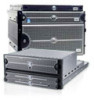
...use a Fibre Channel Arbitrated Loop (FC-AL) as your needs increase. Disk Drive (0 - 14) Front Bezel Figure 1-1 DAE2P/DAE3P 1-2 DAE2P/DAE3P Hardware Reference Rackmount Cabinet EMC2164stil Its modular, scalable design allows for additional disk storage as the interconnect interface. The examples and ...illustrations in this manual show the rackmounted DAE2P/DAE3P in RAID (Redundant Array of Independent Disk) configurations. You can include 15 hard disk drive/carrier modules. The...
...use a Fibre Channel Arbitrated Loop (FC-AL) as your needs increase. Disk Drive (0 - 14) Front Bezel Figure 1-1 DAE2P/DAE3P 1-2 DAE2P/DAE3P Hardware Reference Rackmount Cabinet EMC2164stil Its modular, scalable design allows for additional disk storage as the interconnect interface. The examples and ...illustrations in this manual show the rackmounted DAE2P/DAE3P in RAID (Redundant Array of Independent Disk) configurations. You can include 15 hard disk drive/carrier modules. The...

Hardware Reference
Page 19
... are field-replaceable units (FRUs), which you can interconnect disk enclosures to manage disks and I/O traffic between enclosures. A DAE2P supports 2- The DAE2P and DAE3P are standard. Highly available configurations require at either 2- Figures 1-2 through1-4 show the disk enclosure components. or 4-gigabit disks...of each component accompany the figures. Other configurations use two, three, four, or more separate cabinets. About DAE2P and DAE3P disk enclosures The DAE2P/DAE3P uses FC-AL link control cards to form a large disk storage system; or 4-gigabit disk modules and ...
... are field-replaceable units (FRUs), which you can interconnect disk enclosures to manage disks and I/O traffic between enclosures. A DAE2P supports 2- The DAE2P and DAE3P are standard. Highly available configurations require at either 2- Figures 1-2 through1-4 show the disk enclosure components. or 4-gigabit disks...of each component accompany the figures. Other configurations use two, three, four, or more separate cabinets. About DAE2P and DAE3P disk enclosures The DAE2P/DAE3P uses FC-AL link control cards to form a large disk storage system; or 4-gigabit disk modules and ...

Hardware Reference
Page 20
... Fault LED (Amber) Power LED (Green or Blue) Disk Activity LED (Green) Fault LED (Amber) EMC2166a Figure 1-2 DAE2P/DAE3P front LED display A blue power LED indicates a DAE3P enclosure operating at two Gb. Your disk enclosure may be installed in a rackmount cabinet as shown in Figure 1-2, the front...LED display contains two status lights for each disk module, and two disk enclosure status lights. As shown in Figure 1-1. About DAE2P and DAE3P disk enclosures For increased clarity, the following figures depict the disk enclosure outside of the enclosure. The power LED is green in...
... Fault LED (Amber) Power LED (Green or Blue) Disk Activity LED (Green) Fault LED (Amber) EMC2166a Figure 1-2 DAE2P/DAE3P front LED display A blue power LED indicates a DAE3P enclosure operating at two Gb. Your disk enclosure may be installed in a rackmount cabinet as shown in Figure 1-2, the front...LED display contains two status lights for each disk module, and two disk enclosure status lights. As shown in Figure 1-1. About DAE2P and DAE3P disk enclosures For increased clarity, the following figures depict the disk enclosure outside of the enclosure. The power LED is green in...

Hardware Reference
Page 21
...1-4 Disk enclosure rear view - LEDs and connectors As shown in CLARiiON) Expansion (Out) Primary (In) ! !! +- PRI EXP +- Introduction 1-5 About DAE2P and DAE3P disk enclosures Power/Cooling Module B Link Control Card B EXP PRI PRI # PRI EXP EXP ! !! ! !! # EXP PRI Power/Cooling Module A Figure... 1-3 DAE2P/DAE3P rear components Link Control Card A EMC3232 SPS (Not used in Figure 1-5, an enclosure address (EA) indicator is located on each LCC. (The...
...1-4 Disk enclosure rear view - LEDs and connectors As shown in CLARiiON) Expansion (Out) Primary (In) ! !! +- PRI EXP +- Introduction 1-5 About DAE2P and DAE3P disk enclosures Power/Cooling Module B Link Control Card B EXP PRI PRI # PRI EXP EXP ! !! ! !! # EXP PRI Power/Cooling Module A Figure... 1-3 DAE2P/DAE3P rear components Link Control Card A EMC3232 SPS (Not used in Figure 1-5, an enclosure address (EA) indicator is located on each LCC. (The...