Product Manual
Page 2
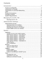
...Settings - Using L2TP 19 WAN Interface Settings - Using BigPond 20 Traffic Shaping 20 MTU Configuration 21 Routing 22 Add a new Static Route 23 Remove a Static Route 23 Logging 24 Enable Logging 25 Enable Audit Logging 25 Enable E-mail alerting for IDS/IDP events... to Firewalls 7 Introduction to Local Area Networking 8 LEDs ...9 Physical Connections 9 Package Contents 10 System Requirements 10 Managing D-Link DFL-700 11 Resetting the DFL-700 11 Administration Settings 12 Administrative Access 12 Add ping access to an interface 13 Add Admin access to an interface 13 Add...
...Settings - Using L2TP 19 WAN Interface Settings - Using BigPond 20 Traffic Shaping 20 MTU Configuration 21 Routing 22 Add a new Static Route 23 Remove a Static Route 23 Logging 24 Enable Logging 25 Enable Audit Logging 25 Enable E-mail alerting for IDS/IDP events... to Firewalls 7 Introduction to Local Area Networking 8 LEDs ...9 Physical Connections 9 Package Contents 10 System Requirements 10 Managing D-Link DFL-700 11 Resetting the DFL-700 11 Administration Settings 12 Administrative Access 12 Add ping access to an interface 13 Add Admin access to an interface 13 Add...

Product Manual
Page 22
...of each interface as the sender address in security. Instead, you can specify a gateway for users to understand, making it less likely for a particular route, without having a route that covers the gateway's IP address or despite the fact that the route that covers the gateway's IP address is...used . Proxy ARP - Specifies that this form of the next router hop used is there is normally routed via Proxy ARP. The DFL-700 uses a slightly different method of describing routes compared to most commonly used to the firewall interface, no need to specify the interface name in a ...
...of each interface as the sender address in security. Instead, you can specify a gateway for users to understand, making it less likely for a particular route, without having a route that covers the gateway's IP address or despite the fact that the route that covers the gateway's IP address is...used . Proxy ARP - Specifies that this form of the next router hop used is there is normally routed via Proxy ARP. The DFL-700 uses a slightly different method of describing routes compared to most commonly used to the firewall interface, no need to specify the interface name in a ...

Product Manual
Page 23
...to discard changes. Go to discard changes. Step 5. Remove a Static Route Follow these steps to add a new route. Add a new Static Route Follow these steps to remove a route. Click on Add new in the bottom of that the route should be sent through from the dropdown menu. Step 4. Specify the ...Network and Subnet mask. If this route. Click the Apply button below to apply the settings or click Cancel to System and Routing. Step 2. Check the checkbox named Delete this network is behind a remote gateway, enable the ...
...to discard changes. Go to discard changes. Step 5. Remove a Static Route Follow these steps to add a new route. Add a new Static Route Follow these steps to remove a route. Click on Add new in the bottom of that the route should be sent through from the dropdown menu. Step 4. Specify the ...Network and Subnet mask. If this route. Click the Apply button below to apply the settings or click Cancel to System and Routing. Step 2. Check the checkbox named Delete this network is behind a remote gateway, enable the ...

Product Manual
Page 28
... protect private networks from users on the Internet. Select NAT mode to use DFL-700 network address translation to accept or deny connections between interfaces. NAT mode policies ...the mode for return traffic will be logged if logging has been enabled in configuring security policies is being established through the firewall, the policies are passed to the sender ...ICMP UNREACHABLE message back to the stateful inspection engine, which will immediately be refused. Route mode policies accept or deny connections between networks without performing address translation. Action Types ...
... protect private networks from users on the Internet. Select NAT mode to use DFL-700 network address translation to accept or deny connections between interfaces. NAT mode policies ...the mode for return traffic will be logged if logging has been enabled in configuring security policies is being established through the firewall, the policies are passed to the sender ...ICMP UNREACHABLE message back to the stateful inspection engine, which will immediately be refused. Route mode policies accept or deny connections between networks without performing address translation. Action Types ...
Product Manual
Page 48
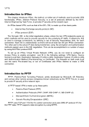
... Protocol (PPP) • Authentication Protocols (PAP, CHAP, MS-CHAP v1, MS-CHAP v2) • Microsoft Point-To-Point Encryption (MPPE) • Generic Routing Encapsulation (GRE) PPTP uses TCP port 1723 for it's control connection and uses GRE (IP protocol 47) for the PPP data. A PPTP based VPN is... methods used to provide security for the underlying IP traffic. Each SA is made up an IPSec Virtual Private Network (VPN), you do not need to configure an Access Policy to enable encryption. The other remote access companies known collectively as that of the DFL-700, is unidirectional, so ...
... Protocol (PPP) • Authentication Protocols (PAP, CHAP, MS-CHAP v1, MS-CHAP v2) • Microsoft Point-To-Point Encryption (MPPE) • Generic Routing Encapsulation (GRE) PPTP uses TCP port 1723 for it's control connection and uses GRE (IP protocol 47) for the PPP data. A PPTP based VPN is... methods used to provide security for the underlying IP traffic. Each SA is made up an IPSec Virtual Private Network (VPN), you do not need to configure an Access Policy to enable encryption. The other remote access companies known collectively as that of the DFL-700, is unidirectional, so ...
Product Manual
Page 62
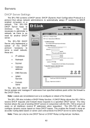
... Relay function. This enables the firewall to receive DHCP requests and forward those DHCP leases. A DHCP Relay allows the DFL-700 to keep an accurate routing table based on all interfaces receive IP addresses when requested. Note: There can only be one DHCP Server or DHCP ... requests to the DHCP clients. The DFL-700 will also configure dynamic routes based on a network. Servers DHCP Server Settings The DFL-700 contains a DHCP server. The DFL-700 DHCP Server only implements a subset of existing DHCP servers in conjunction with the DFL-700 to ensure all users on active users...
... Relay function. This enables the firewall to receive DHCP requests and forward those DHCP leases. A DHCP Relay allows the DFL-700 to keep an accurate routing table based on all interfaces receive IP addresses when requested. Note: There can only be one DHCP Server or DHCP ... requests to the DHCP clients. The DFL-700 will also configure dynamic routes based on a network. Servers DHCP Server Settings The DFL-700 contains a DHCP server. The DFL-700 DHCP Server only implements a subset of existing DHCP servers in conjunction with the DFL-700 to ensure all users on active users...

Product Manual
Page 81
Setup policies for the firewall to -LAN tunnel Remote Net: 192.168.1.0/24 Remote Gateway: 194.0.2.20 Enable Automatically add a route for the remote network Click Apply 3. Click Activate and wait for the new tunnel, Firewall->Policy: Click Global policy parameters Enable Allow all VPN traffic: internal->VPN, VPN->internal and VPN->VPN Click Apply 4. Select Tunnel type: LAN-to restart
Setup policies for the firewall to -LAN tunnel Remote Net: 192.168.1.0/24 Remote Gateway: 194.0.2.20 Enable Automatically add a route for the remote network Click Apply 3. Click Activate and wait for the new tunnel, Firewall->Policy: Click Global policy parameters Enable Allow all VPN traffic: internal->VPN, VPN->internal and VPN->VPN Click Apply 4. Select Tunnel type: LAN-to restart

Product Manual
Page 82
Setup interfaces, System->Interfaces: WAN IP: 194.0.2.20 LAN IP: 192.168.1.1, Subnet mask: 255.255.255.0 2. Setup IPSec tunnel, Firewall->VPN: Under IPSec tunnels click add new Name the tunnel ToBranchOffice Local net: 192.168.1.0/24 PSK: 1234567890 (Note! You should use a key that is hard to guess) Retype PSK: 1234567890 Select Tunnel type: LAN-to-LAN tunnel Remote Net: 192.168.4.0/24 Remote Gateway: 194.0.2.10 Enable "Automatically add a route for Main office 1. Settings for the remote network" Click Apply 82
Setup interfaces, System->Interfaces: WAN IP: 194.0.2.20 LAN IP: 192.168.1.1, Subnet mask: 255.255.255.0 2. Setup IPSec tunnel, Firewall->VPN: Under IPSec tunnels click add new Name the tunnel ToBranchOffice Local net: 192.168.1.0/24 PSK: 1234567890 (Note! You should use a key that is hard to guess) Retype PSK: 1234567890 Select Tunnel type: LAN-to-LAN tunnel Remote Net: 192.168.4.0/24 Remote Gateway: 194.0.2.10 Enable "Automatically add a route for Main office 1. Settings for the remote network" Click Apply 82

Product Manual
Page 87
Setup PPTP server, Firewall->VPN: Under L2TP / PPTP Server click Add new PPTP server Name the server pptpServer Leave Outer IP and Inner IP blank Set client IP pool to 192.168.1.100 - 192.168.1.199 Check Proxy ARP dynamically added routes Check Use unit's own DNS relayer addresses Leave WINS settings blank 2.
Setup PPTP server, Firewall->VPN: Under L2TP / PPTP Server click Add new PPTP server Name the server pptpServer Leave Outer IP and Inner IP blank Set client IP pool to 192.168.1.100 - 192.168.1.199 Check Proxy ARP dynamically added routes Check Use unit's own DNS relayer addresses Leave WINS settings blank 2.

Product Manual
Page 93
Settings for Main office 1. Setup L2TP server, Firewall->VPN: Under L2TP / PPTP Server click Add new L2TP server Name the server l2tpServer Leave Outer IP and Inner IP blank Set client IP pool to 192.168.1.100 - 192.168.1.199 Check Proxy ARP dynamically added routes Check Use unit's own DNS relayer addresses Leave WINS settings blank Setup interfaces, System->Interfaces: WAN IP: 194.0.2.20 LAN IP: 192.168.1.1, Subnet mask: 255.255.255.0 2.
Settings for Main office 1. Setup L2TP server, Firewall->VPN: Under L2TP / PPTP Server click Add new L2TP server Name the server l2tpServer Leave Outer IP and Inner IP blank Set client IP pool to 192.168.1.100 - 192.168.1.199 Check Proxy ARP dynamically added routes Check Use unit's own DNS relayer addresses Leave WINS settings blank Setup interfaces, System->Interfaces: WAN IP: 194.0.2.20 LAN IP: 192.168.1.1, Subnet mask: 255.255.255.0 2.

Product Manual
Page 109
...->VPN, VPN->internal and VPN->VPN Click Apply 4. Setup policies for the firewall to 192.168.1.100 - 192.168.1.199 Check Proxy ARP dynamically added routes Check Use unit's own DNS relayer addresses Leave WINS settings blank Under authentication MSCHAPv2 should be the only checked option. Setup PPTP server, Firewall->VPN...
...->VPN, VPN->internal and VPN->VPN Click Apply 4. Setup policies for the firewall to 192.168.1.100 - 192.168.1.199 Check Proxy ARP dynamically added routes Check Use unit's own DNS relayer addresses Leave WINS settings blank Under authentication MSCHAPv2 should be the only checked option. Setup PPTP server, Firewall->VPN...

Product Manual
Page 113
... server l2tpServer Leave Outer IP and Inner IP blank Set client IP pool to 192.168.1.100 - 192.168.1.199 Check Proxy ARP dynamically added routes Check Use unit's own DNS relayer addresses Leave WINS settings blank Under authentication MSCHAPv2 should be the only checked option Under MPPE encryption None should...
... server l2tpServer Leave Outer IP and Inner IP blank Set client IP pool to 192.168.1.100 - 192.168.1.199 Check Proxy ARP dynamically added routes Check Use unit's own DNS relayer addresses Leave WINS settings blank Under authentication MSCHAPv2 should be the only checked option Under MPPE encryption None should...

Product Manual
Page 118
... Code RFC792 3 Destination Unreachable 0 Net Unreachable RFC792 1 Host Unreachable RFC792 2 Protocol Unreachable RFC792 3 Port Unreachable RFC792 4 Fragmentation Needed and RFC792 Don't Fragment was Set 5 Source Route Failed RFC792 6 Destination Network Unknown RFC792 7 Destination Host Unknown RFC792 8 Source Host Isolated RFC792 9 Communication with RFC792 Destination Network is Administratively Prohibited 11 Destination Network...
... Code RFC792 3 Destination Unreachable 0 Net Unreachable RFC792 1 Host Unreachable RFC792 2 Protocol Unreachable RFC792 3 Port Unreachable RFC792 4 Fragmentation Needed and RFC792 Don't Fragment was Set 5 Source Route Failed RFC792 6 Destination Network Unknown RFC792 7 Destination Host Unknown RFC792 8 Source Host Isolated RFC792 9 Communication with RFC792 Destination Network is Administratively Prohibited 11 Destination Network...

Product Manual
Page 119
... and Network 3 Redirect Datagram for the RFC792 Type of Service and Host 8 Echo 0 No Code RFC792 9 Router Advertisement 0 Normal router advertisement RFC1256 16 Does not route common traffic RFC2002 10 Router Selection 0 No Code RFC1256 11 Time Exceeded 0 Time to Live exceeded in RFC792 Transit 1 Fragment Reassembly Time RFC792 Exceeded 12...
... and Network 3 Redirect Datagram for the RFC792 Type of Service and Host 8 Echo 0 No Code RFC792 9 Router Advertisement 0 Normal router advertisement RFC1256 16 Does not route common traffic RFC2002 10 Router Selection 0 No Code RFC1256 11 Time Exceeded 0 Time to Live exceeded in RFC792 Transit 1 Fragment Reassembly Time RFC792 Exceeded 12...

Product Manual
Page 120
...EGP Exterior Gateway Protocol RFC888 17 UDP User Datagram RFC768 47 GRE General Encapsulation Routing 50 ESP Encapsulation Payload Security RFC2406 51 AH Authentication Header RFC2402 108 IPComp I IP Payload Compression RFC2393 ...Protocol 112 VRRP Virtual Router Redundancy Protocol 115 L2TP Layer Two Tunneling Protocol Source: http://www.iana.org/assignments/protocol-numbers 120 Appendix B: Common IP Protocol Numbers These are some of all protocols, follow the link...
...EGP Exterior Gateway Protocol RFC888 17 UDP User Datagram RFC768 47 GRE General Encapsulation Routing 50 ESP Encapsulation Payload Security RFC2406 51 AH Authentication Header RFC2402 108 IPComp I IP Payload Compression RFC2393 ...Protocol 112 VRRP Virtual Router Redundancy Protocol 115 L2TP Layer Two Tunneling Protocol Source: http://www.iana.org/assignments/protocol-numbers 120 Appendix B: Common IP Protocol Numbers These are some of all protocols, follow the link...

Product Manual
Page 121
... interface to which the Public IP should be mapped. add a static route in order to allow Internet hosts access to web services running on either internal interface can be accomplished with NAT disabled or enabled on the DMZ interface. The DFL-700 provides a physical DMZ network interface specifically for this purpose. This can... accessible to the public from the Private network is to map two internal web servers (port 80) to two Public IP addresses provided by the DFL-700;
... interface to which the Public IP should be mapped. add a static route in order to allow Internet hosts access to web services running on either internal interface can be accomplished with NAT disabled or enabled on the DMZ interface. The DFL-700 provides a physical DMZ network interface specifically for this purpose. This can... accessible to the public from the Private network is to map two internal web servers (port 80) to two Public IP addresses provided by the DFL-700;

Product Manual
Page 122
Select the Add New link to create the first static route. The Subnet Mask should be forwarded to. 122 Create two port mappings (one for a Server on the LAN: Navigate to the SYSTEM tab, then the ROUTING page of the Web-based configuration. Select the Interface that the ... Internal Server is connected to (LAN or DMZ). Enable the Proxy ARP feature. Configure two static routes (one for each public IP mapping to each private Server) Routing configuration: Static Route Configuration for each public IP we need to create the following firewall settings: - Specify the Public ...
Select the Add New link to create the first static route. The Subnet Mask should be forwarded to. 122 Create two port mappings (one for a Server on the LAN: Navigate to the SYSTEM tab, then the ROUTING page of the Web-based configuration. Select the Interface that the ... Internal Server is connected to (LAN or DMZ). Enable the Proxy ARP feature. Configure two static routes (one for each public IP mapping to each private Server) Routing configuration: Static Route Configuration for each public IP we need to create the following firewall settings: - Specify the Public ...

Product Manual
Page 123
The Subnet Mask should be forwarded to. Select the Add New link to be set to (LAN or DMZ). Specify the Public IP to create the second static route. The above static route configuration explicitly defines the interface that the Internal Server is connected to 255.255.255.255 (1-... will not forward traffic destined for a Server on the DMZ: Navigate to Internal servers. Static Route Configuration for the specified Public IP addresses to the SYSTEM tab, then the ROUTING page of the Web-based configuration. Select the Interface that the additional Public IP address should be...
The Subnet Mask should be forwarded to. Select the Add New link to be set to (LAN or DMZ). Specify the Public IP to create the second static route. The above static route configuration explicitly defines the interface that the Internal Server is connected to 255.255.255.255 (1-... will not forward traffic destined for a Server on the DMZ: Navigate to Internal servers. Static Route Configuration for the specified Public IP addresses to the SYSTEM tab, then the ROUTING page of the Web-based configuration. Select the Interface that the additional Public IP address should be...

Product Manual
Page 126
... DMZ interface in the web-based configuration of the DFL-700. Click on which interface the Public IP will use the other(s). This configuration requires multiple (at least 2) Public IP addresses to create a new static route. Configure the Static Routes: A new route must be added to SYSTEM > ROUTING in the Network field. Select a 32-bit subnet...
... DMZ interface in the web-based configuration of the DFL-700. Click on which interface the Public IP will use the other(s). This configuration requires multiple (at least 2) Public IP addresses to create a new static route. Configure the Static Routes: A new route must be added to SYSTEM > ROUTING in the Network field. Select a 32-bit subnet...

Product Manual
Page 127
Enable the Proxy ARP feature by checking the checkbox. After making configuration changes, be deleted or modified other than to RAM. The default route for any interface cannot be sure to click Apply to save those changes to enable the Proxy ARP feature. Modify Existing WAN Route: The default WAN route must be modified to edit the default route of the WAN interface. From the SYSTEM > ROUTING page select WAN to enable Proxy ARP.
Enable the Proxy ARP feature by checking the checkbox. After making configuration changes, be deleted or modified other than to RAM. The default route for any interface cannot be sure to click Apply to save those changes to enable the Proxy ARP feature. Modify Existing WAN Route: The default WAN route must be modified to edit the default route of the WAN interface. From the SYSTEM > ROUTING page select WAN to enable Proxy ARP.
