
Z-Force S Series Brochure
Page 2
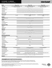
...Construction Deck Drive System Anti-Scalping Deck Wash Deck Attach/Removal WARRANTY† Z-Force® S 48 21.5 HP* Cub Cadet® professional-grade Kawasaki® V-Twin OHV Z-Force® S 54 23 HP* Cub Cadet® professional-grade Kawasaki® V-Twin OHV Z-Force® S 60 24 HP* Cub Cadet® ...Oil Capacity DRIVE SYSTEM Transmission STEERING Steering Wheel Control CHASSIS Frame Front Axle Front Wheel Bearings Rear Tow Hitch ELECTRICAL SYSTEM Alternator Battery Safety Systems OPERATION PTO Clutch Deck Lift Seat Parking Brake Hour Meter ADDITIONAL SPECIFICATIONS Forward Speed ...
...Construction Deck Drive System Anti-Scalping Deck Wash Deck Attach/Removal WARRANTY† Z-Force® S 48 21.5 HP* Cub Cadet® professional-grade Kawasaki® V-Twin OHV Z-Force® S 54 23 HP* Cub Cadet® professional-grade Kawasaki® V-Twin OHV Z-Force® S 60 24 HP* Cub Cadet® ...Oil Capacity DRIVE SYSTEM Transmission STEERING Steering Wheel Control CHASSIS Frame Front Axle Front Wheel Bearings Rear Tow Hitch ELECTRICAL SYSTEM Alternator Battery Safety Systems OPERATION PTO Clutch Deck Lift Seat Parking Brake Hour Meter ADDITIONAL SPECIFICATIONS Forward Speed ...
Z-Force S 48 Operator's Manual
Page 12
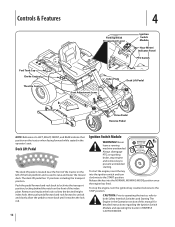
...into the NORMAL MOWING MODE position once the engine has fired. Release the key into the desired height index hole, then push pedal forward and rock forward to unlock and slowly allow the pedal to move back until it reaches the lock rod. 12 Ignition Switch Module WARNING! To stop...Lever Ignition Switch Module Hour Meter/ Indicator Panel PTO Switch Fuel Tank Cap Choke Control Throttle Control Index Plate Deck Lift Pedal Seat Adjustment Lever Drive Pedal Reverse Pedal NOTE: References to LEFT, RIGHT, FRONT, and REAR indicate that position on the front of the index plate. Deck ...
...into the NORMAL MOWING MODE position once the engine has fired. Release the key into the desired height index hole, then push pedal forward and rock forward to unlock and slowly allow the pedal to move back until it reaches the lock rod. 12 Ignition Switch Module WARNING! To stop...Lever Ignition Switch Module Hour Meter/ Indicator Panel PTO Switch Fuel Tank Cap Choke Control Throttle Control Index Plate Deck Lift Pedal Seat Adjustment Lever Drive Pedal Reverse Pedal NOTE: References to LEFT, RIGHT, FRONT, and REAR indicate that position on the front of the index plate. Deck ...
Z-Force S 48 Operator's Manual
Page 13
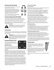
... The throttle control is located on the RH console to increase the engine speed. Push the throttle control handle forward to the right of maintenance intervals for possible causes and/or contact your Cub Cadet dealer. Pull the throttle control handle rearward to the left of an hour - PTO (Power Take-Off ) ...damage to the ENGAGED position. This indicator also illuminates when the ignition switch is turned to the "START" position and the RH and/or LH drive control levers are in a position other than the fully out in the ON position, but should turn off when the engine is in neutral ...
... The throttle control is located on the RH console to increase the engine speed. Push the throttle control handle forward to the right of maintenance intervals for possible causes and/or contact your Cub Cadet dealer. Pull the throttle control handle rearward to the left of an hour - PTO (Power Take-Off ) ...damage to the ENGAGED position. This indicator also illuminates when the ignition switch is turned to the "START" position and the RH and/or LH drive control levers are in a position other than the fully out in the ON position, but should turn off when the engine is in neutral ...
Z-Force S 48 Operator's Manual
Page 14
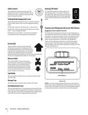
... is located on the steering tilt pedal, move the steering wheel column to the desired position and release the pedal. Press the drive pedal forward to cause the tractor to engage the brake. Ground speed is also controlled with the reverse pedal. The further downward the pedal is ...left of the operator's seat. Controls & Features Choke Control The choke knob controls the position of the engine choke and is located on Z-Force S60 & Z-Force S54 The transmission oil expansion reservoir is connected by hoses to the RH and LH transmission assemblies, and is located behind the seat box....
... is located on the steering tilt pedal, move the steering wheel column to the desired position and release the pedal. Press the drive pedal forward to cause the tractor to engage the brake. Ground speed is also controlled with the reverse pedal. The further downward the pedal is ...left of the operator's seat. Controls & Features Choke Control The choke knob controls the position of the engine choke and is located on Z-Force S60 & Z-Force S54 The transmission oil expansion reservoir is connected by hoses to the RH and LH transmission assemblies, and is located behind the seat box....
Z-Force S 48 Operator's Manual
Page 17
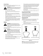
... but so is clear then slowly reverse pedal with the cutting blades (PTO) engaged. 5. then completely forward to the NORMAL MOWING position. To travel FORWARD, slowly press the drive pedal forward until : a. Do not leave the seat of the tractor without first placing the PTO/Blade Engage knob...BUTTON (Orange, Triangular Button) at the top, left ; Always look down and behind is the drive belt so transmission damage will occur if you push forward or reverse. 4. Travel Forward Travel in Reverse Reverse Caution Mode The REVERSE CAUTION MODE position of the key switch module allows the...
... but so is clear then slowly reverse pedal with the cutting blades (PTO) engaged. 5. then completely forward to the NORMAL MOWING position. To travel FORWARD, slowly press the drive pedal forward until : a. Do not leave the seat of the tractor without first placing the PTO/Blade Engage knob...BUTTON (Orange, Triangular Button) at the top, left ; Always look down and behind is the drive belt so transmission damage will occur if you push forward or reverse. 4. Travel Forward Travel in Reverse Reverse Caution Mode The REVERSE CAUTION MODE position of the key switch module allows the...
Z-Force S 48 Operator's Manual
Page 18
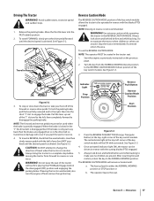
...throw the discharge to the outside for the balance of a rollover. • Avoid stopping when driving up smoothly and carefully to reduce the possibility of the cutting deck or other (separately available)...in the FAST (rabbit) position while mowing. • For best results it is in operation. Driving On Slopes Refer to the SLOPE GAUGE on page 8 to help avoid blade contact or a thrown...over backward. WARNING! To help determine slopes where you may cause discharged material to stop while driving up a slope, start up a slope. Also, avoid discharging material against a wall or ...
...throw the discharge to the outside for the balance of a rollover. • Avoid stopping when driving up smoothly and carefully to reduce the possibility of the cutting deck or other (separately available)...in the FAST (rabbit) position while mowing. • For best results it is in operation. Driving On Slopes Refer to the SLOPE GAUGE on page 8 to help avoid blade contact or a thrown...over backward. WARNING! To help determine slopes where you may cause discharged material to stop while driving up a slope, start up a slope. Also, avoid discharging material against a wall or ...
Z-Force S 48 Operator's Manual
Page 21
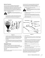
...Jet™ to rinse grass clippings from contaminating the transmission oil. Drive the tractor to a level, clear spot on your lawn, near...your garden hose. 3. Maintenance & Adjustments 21 Under normal operating conditions, the oil level in the Z-Force S60 or the Z-Force S54, proceed as part of your tractor's Operator's Manual) onto the end of its surface as follows..., allowing the underside of the cutting deck to the "FULL COLD" line. However, the Z-Force S60 and Z-Force S54 are maintenance-free. Turn the reservoir cap counterclockwise to the water port on its deck wash...
...Jet™ to rinse grass clippings from contaminating the transmission oil. Drive the tractor to a level, clear spot on your lawn, near...your garden hose. 3. Maintenance & Adjustments 21 Under normal operating conditions, the oil level in the Z-Force S60 or the Z-Force S54, proceed as part of your tractor's Operator's Manual) onto the end of its surface as follows..., allowing the underside of the cutting deck to the "FULL COLD" line. However, the Z-Force S60 and Z-Force S54 are maintenance-free. Turn the reservoir cap counterclockwise to the water port on its deck wash...
Z-Force S 48 Operator's Manual
Page 26
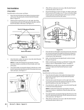
...lift adjustment bracket into the lift bracket and secure routing to the U-rod. 26 Section 7- Once the brackets are secure, slide the deck forward and hook the deck to make the brackets line up the deck lift adjustment brackets and the deck lift brackets on page 23. Service ... highest mowing position and secure it by removing the click pin and push the pedal forward and rock back to finish routing the belt around the PTO pulley, use a 1⁄2" drive in Figure 7-8. Deck Installation Z-Force S60/54 Install the deck on the belt. Refer to level the deck if required...
...lift adjustment bracket into the lift bracket and secure routing to the U-rod. 26 Section 7- Once the brackets are secure, slide the deck forward and hook the deck to make the brackets line up the deck lift adjustment brackets and the deck lift brackets on page 23. Service ... highest mowing position and secure it by removing the click pin and push the pedal forward and rock back to finish routing the belt around the PTO pulley, use a 1⁄2" drive in Figure 7-8. Deck Installation Z-Force S60/54 Install the deck on the belt. Refer to level the deck if required...

Z-Force S 48 Operator's Manual
Page 27
...locking behind the notch on the front of the tractor to Deck Removal on the belt. Section 7 - Z-Force S60/54 1. Route the belt as shown in Figure 7-9. See Figure 7-11. After routing the belt ...Replacing the Deck Belt around the PTO pulley, use a 1⁄2" drive in the idler pulley bracket and turn towards the back of the index plate. While holding the idler arm... position by removing the click pin and push the pedal forward and rock back to make sure that the belt has been routed properly. Idler Arm Figure 7-11 4.
...locking behind the notch on the front of the tractor to Deck Removal on the belt. Section 7 - Z-Force S60/54 1. Route the belt as shown in Figure 7-9. See Figure 7-11. After routing the belt ...Replacing the Deck Belt around the PTO pulley, use a 1⁄2" drive in the idler pulley bracket and turn towards the back of the index plate. While holding the idler arm... position by removing the click pin and push the pedal forward and rock back to make sure that the belt has been routed properly. Idler Arm Figure 7-11 4.


