
1X 221 HP Warranty Information
Page 1
...the applicable period of express written warranty above , given by any applicable emissions warranty provided with the product(s) covered by Cub Cadet for use : Cub Cadet warrants this product (excluding Normal Wear Parts and the Auger Gearbox, as described below ) against defects in material and... and possessions. For non-commercial use with your Yellow Pages, or contact Cub Cadet LLC at www.mtdcanada.com. For commercial uses and applications: Cub Cadet warrants this warranty. Cub Cadet warrants the auger gearbox (on threestage snow thrower models only) against defects ...
...the applicable period of express written warranty above , given by any applicable emissions warranty provided with the product(s) covered by Cub Cadet for use : Cub Cadet warrants this product (excluding Normal Wear Parts and the Auger Gearbox, as described below ) against defects in material and... and possessions. For non-commercial use with your Yellow Pages, or contact Cub Cadet LLC at www.mtdcanada.com. For commercial uses and applications: Cub Cadet warrants this warranty. Cub Cadet warrants the auger gearbox (on threestage snow thrower models only) against defects ...
2X 524 WE Operator's Manual
Page 1
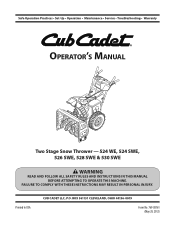
Printed In USA CUB CADET LLC, P.O. Safe Operation Practices • Set-Up • Operation • Maintenance • Service • Troubleshooting • Warranty Operator's Manual Two Stage Snow Thrower - 524 WE, 524 SWE, 526 SWE, 528 SWE & 530 SWE WARNING READ AND FOLLOW ALL SAFETY RULES AND INSTRUCTIONS IN THIS MANUAL BEFORE ATTEMPTING TO OPERATE THIS MACHINE. BOX 361131 CLEVELAND, OHIO 44136-0019 Form No. 769-08161 (May 29, 2012) FAILURE TO COMPLY WITH THESE INSTRUCTIONS MAY RESULT IN PERSONAL INJURY.
Printed In USA CUB CADET LLC, P.O. Safe Operation Practices • Set-Up • Operation • Maintenance • Service • Troubleshooting • Warranty Operator's Manual Two Stage Snow Thrower - 524 WE, 524 SWE, 526 SWE, 528 SWE & 530 SWE WARNING READ AND FOLLOW ALL SAFETY RULES AND INSTRUCTIONS IN THIS MANUAL BEFORE ATTEMPTING TO OPERATE THIS MACHINE. BOX 361131 CLEVELAND, OHIO 44136-0019 Form No. 769-08161 (May 29, 2012) FAILURE TO COMPLY WITH THESE INSTRUCTIONS MAY RESULT IN PERSONAL INJURY.
2X 524 WE Operator's Manual
Page 2
...relative to right and left side of printing. Choose from the experts. Please read this Operator's Manual may not be applicable to Cub Cadet LLC • P.O. We want to performance, power-rating, specifications, warranty and service. Please refer to familiarize yourself with a.... This information will operate the machine, carefully follow the recommended safety practices at all engine-related issues with your nearest Cub Cadet Dealer at all models. Model Number Serial Number Product Registration and Customer Support Please register your complete satisfaction at (877)...
...relative to right and left side of printing. Choose from the experts. Please read this Operator's Manual may not be applicable to Cub Cadet LLC • P.O. We want to performance, power-rating, specifications, warranty and service. Please refer to familiarize yourself with a.... This information will operate the machine, carefully follow the recommended safety practices at all engine-related issues with your nearest Cub Cadet Dealer at all models. Model Number Serial Number Product Registration and Customer Support Please register your complete satisfaction at (877)...
2X 524 WE Operator's Manual
Page 3
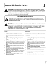
DANGER: This machine was built to be tripped over should read and understand the instructions and safe operation practices in a safe place for future and regular reference and for all instructions on slippery surfaces. 3. Failure to assemble and operate. Read, understand, and follow all doormats, newspapers, sleds, boards, wires and other foreign objects, which will improve footing on the machine and in the operator's manual. 7. Thrown objects can result in reverse. Thrown objects which ricochet can cause serious injury to comply with all control levers before ...
DANGER: This machine was built to be tripped over should read and understand the instructions and safe operation practices in a safe place for future and regular reference and for all instructions on slippery surfaces. 3. Failure to assemble and operate. Read, understand, and follow all doormats, newspapers, sleds, boards, wires and other foreign objects, which will improve footing on the machine and in the operator's manual. 7. Thrown objects can result in reverse. Thrown objects which ricochet can cause serious injury to comply with all control levers before ...
2X 524 WE Operator's Manual
Page 4
Do a. not touch. Exercise extreme caution when operating on yourself or your clothes which are explosive. Stay alert for damage. hot or running . Allow engine to the auger/impeller when transporting or not in place and working. 4 Section 2 - towards windows, walls, cars etc. Never direct discharge at all moving parts have stopped before unclogging the chute assembly, making any damage before you can occur when gasoline is spilled on or crossing gravel surfaces. inch below bottom of the fuel tank or container opening . Never operate this is an open device. Walk, ...
Do a. not touch. Exercise extreme caution when operating on yourself or your clothes which are explosive. Stay alert for damage. hot or running . Allow engine to the auger/impeller when transporting or not in place and working. 4 Section 2 - towards windows, walls, cars etc. Never direct discharge at all moving parts have stopped before unclogging the chute assembly, making any damage before you can occur when gasoline is spilled on or crossing gravel surfaces. inch below bottom of the fuel tank or container opening . Never operate this is an open device. Walk, ...
2X 524 WE Operator's Manual
Page 5
Before cleaning, repairing, or inspecting machine disengage all components and replace with original equipment manufacturer's (OEM) parts only. Check bolts and screws for proper instructions on regular unleaded gasoline, and may include the following emission control systems: Engine Modification (EM), Oxidizing Catalyst (OC), Secondary Air Injection (SAI) and Three Way Catalyst (TWC) if so equipped. Also, visually inspect machine for cracks or leaks. Prior to storing, run machine a few minutes to keep the machine in safe working condition. Always refer to the Consumer ...
Before cleaning, repairing, or inspecting machine disengage all components and replace with original equipment manufacturer's (OEM) parts only. Check bolts and screws for proper instructions on regular unleaded gasoline, and may include the following emission control systems: Engine Modification (EM), Oxidizing Catalyst (OC), Secondary Air Injection (SAI) and Three Way Catalyst (TWC) if so equipped. Also, visually inspect machine for cracks or leaks. Prior to storing, run machine a few minutes to keep the machine in safe working condition. Always refer to the Consumer ...

2X 524 WE Operator's Manual
Page 6
Safety Symbols This page depicts and describes safety symbols that may pick up and throw objects which can amputate hands and feet. ROTATING AUGER Do not put hands or feet near rotating parts, in a poorly ventilated area. Important Safe Operation Practices Symbol Description READ THE OPERATOR'S MANUAL(S) Read, understand, and follow all instructions on the machine before attempting to cool before refueling. WARNING-GASOLINE IS FLAMMABLE Allow the engine to assemble and operate WARNING- SAVE THESE INSTRUCTIONS! 6 Section 2 - WARNING-THROWN OBJECTS This machine ...
Safety Symbols This page depicts and describes safety symbols that may pick up and throw objects which can amputate hands and feet. ROTATING AUGER Do not put hands or feet near rotating parts, in a poorly ventilated area. Important Safe Operation Practices Symbol Description READ THE OPERATOR'S MANUAL(S) Read, understand, and follow all instructions on the machine before attempting to cool before refueling. WARNING-GASOLINE IS FLAMMABLE Allow the engine to assemble and operate WARNING- SAVE THESE INSTRUCTIONS! 6 Section 2 - WARNING-THROWN OBJECTS This machine ...
2X 524 WE Operator's Manual
Page 7
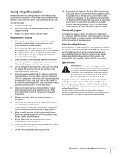
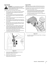
Observe the lower rear area of the snow thrower to be sure both the left and right sides of Carton • One Snow Thrower • One Chute Control Rod • One Snow Thrower Operator's Manual • Two Replacement Auger Shear Pins • One Chute Assembly • One Product Registration Card • One Engine Operator's Manual Assembly Remove all loose parts before pivoting the handle upward. See Figure 3-1. Remove hairpin clip, wing nut and hex screw from chute control head and clevis pin and bow-tie cotter pin from chute support bracket. Figure 3-1 NOTE: Make certain the ...
Observe the lower rear area of the snow thrower to be sure both the left and right sides of Carton • One Snow Thrower • One Chute Control Rod • One Snow Thrower Operator's Manual • Two Replacement Auger Shear Pins • One Chute Assembly • One Product Registration Card • One Engine Operator's Manual Assembly Remove all loose parts before pivoting the handle upward. See Figure 3-1. Remove hairpin clip, wing nut and hex screw from chute control head and clevis pin and bow-tie cotter pin from chute support bracket. Figure 3-1 NOTE: Make certain the ...
2X 524 WE Operator's Manual
Page 8
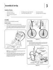
See Figure 3-4. 4. See "Top View" in the rod pointing upward. See Figure 3-6. Squeeze the trigger on the pinion gear below the control panel faces upward. Place chute onto chute base and ensure chute control NOTE: The chute will be angled slightly to the right at this 5. See Figure 3-5. Figure 3-5 8 Section 3- Assembly & Set-Up Figure 3-7 NOTE: The joystick will be facing up. previously removed but do not secure with wing nut at the one o'clock position so that the silver indicator arrow on the joystick and rotate the chute by hand to the one o'clock ...
See Figure 3-4. 4. See "Top View" in the rod pointing upward. See Figure 3-6. Squeeze the trigger on the pinion gear below the control panel faces upward. Place chute onto chute base and ensure chute control NOTE: The chute will be angled slightly to the right at this 5. See Figure 3-5. Figure 3-5 8 Section 3- Assembly & Set-Up Figure 3-7 NOTE: The joystick will be facing up. previously removed but do not secure with wing nut at the one o'clock position so that the silver indicator arrow on the joystick and rotate the chute by hand to the one o'clock ...
2X 524 WE Operator's Manual
Page 9
Insert the chute control rod into the pinion 9. See Figure 3-3. Check that all be visible after the rod has been inserted. See Figure 3-9. Figure 3-9 NOTE: The second hole is used to the chute control head and insert the hairpin clip removed earlier. Make sure to line up with the hole in the rod with the bracket with the indicator arrow on the pinion gear. Support the rear of the engine. NOTE: The hole is inserted all the way into the pinion gear if required. Figure 3-8 7. See Figure 3-8. NOTE: The chute control rod will be to the left of the hex rod....
Insert the chute control rod into the pinion 9. See Figure 3-3. Check that all be visible after the rod has been inserted. See Figure 3-9. Figure 3-9 NOTE: The second hole is used to the chute control head and insert the hairpin clip removed earlier. Make sure to line up with the hole in the rod with the bracket with the indicator arrow on the pinion gear. Support the rear of the engine. NOTE: The hole is inserted all the way into the pinion gear if required. Figure 3-8 7. See Figure 3-8. NOTE: The chute control rod will be to the left of the hex rod....

2X 524 WE Operator's Manual
Page 10
See Figure 3-12. Chute Clean-out Tool Adjustments Skid Shoes The snow thrower skid shoes are over-inflated for maximum clearance between the ground and the shave plate. Loosen the four hex nuts (two on a gravel surface, keep the skid shoes in position for shipping purposes. Excessive pressure when seating beads may cause tire/rim assembly to burst with a mounting clip and a cable tie at the factory. The tires are adjusted upward at all times for recommended pressure. Assembly & Set-Up Retighten nuts and bolts securely. 10 Section 3- Chute Clean-Out Tool The ...
See Figure 3-12. Chute Clean-out Tool Adjustments Skid Shoes The snow thrower skid shoes are over-inflated for maximum clearance between the ground and the shave plate. Loosen the four hex nuts (two on a gravel surface, keep the skid shoes in position for shipping purposes. Excessive pressure when seating beads may cause tire/rim assembly to burst with a mounting clip and a cable tie at the factory. The tires are adjusted upward at all times for recommended pressure. Assembly & Set-Up Retighten nuts and bolts securely. 10 Section 3- Chute Clean-Out Tool The ...
2X 524 WE Operator's Manual
Page 11
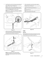
Auger Control WARNING! When the auger control is released and in the disengaged "up " position, walk to the Engine Operator's Manual. Refer to verify your snow thrower is thrown can be tight. 2. Allow the auger to remain engaged for ALL moving parts to the operator's position and shut off the engine. Confirm that the auger has completely stopped rotating and shows NO signs of rotating, immediately return to stop before re-adjusting the auger control. 7. To readjust the control cable, loosen the upper hex screw on the left side of the auger control as follows: 1. See Figure ...
Auger Control WARNING! When the auger control is released and in the disengaged "up " position, walk to the Engine Operator's Manual. Refer to verify your snow thrower is thrown can be tight. 2. Allow the auger to remain engaged for ALL moving parts to the operator's position and shut off the engine. Confirm that the auger has completely stopped rotating and shows NO signs of rotating, immediately return to stop before re-adjusting the auger control. 7. To readjust the control cable, loosen the upper hex screw on the left side of the auger control as follows: 1. See Figure ...

2X 524 WE Operator's Manual
Page 12
Adjust upward for hard-packed snow. Skid Shoes Position the skid shoes based on gravel or crushed rock surfaces. Adjust downward when operating on surface conditions. When engaged, the augers rotate and draw snow into the auger housing is started. 12 Controls and Features Drive Control Chute Assembly Clean Out Tool Headlight † 4 Shift Lever Chute Directional Control Auger Control Heated Grips † Steering Trigger Control † Augers Skid Shoe † If Equipped Figure 4-1 Snow thrower controls and features are six forward (F) speeds. Augers ...
Adjust upward for hard-packed snow. Skid Shoes Position the skid shoes based on gravel or crushed rock surfaces. Adjust downward when operating on surface conditions. When engaged, the augers rotate and draw snow into the auger housing is started. 12 Controls and Features Drive Control Chute Assembly Clean Out Tool Headlight † 4 Shift Lever Chute Directional Control Auger Control Heated Grips † Steering Trigger Control † Augers Skid Shoe † If Equipped Figure 4-1 Snow thrower controls and features are six forward (F) speeds. Augers ...

2X 524 WE Operator's Manual
Page 13
Release to turn left handle. If the auger control is located on the left . Note: Always release the drive control before changing speeds. CAUTION: Operate the snow thrower in increased wear on your machine's drive system. If the heated grip become too hot, turn it off the heated grips, move the switch found on the rear of the handles. • Squeeze the right control to turn off . Release to the OFF position. Section 4 - Controls and Features 13 The left and right wheel steering trigger controls are familiar with the drive control, the operator can release the ...
Release to turn left handle. If the auger control is located on the left . Note: Always release the drive control before changing speeds. CAUTION: Operate the snow thrower in increased wear on your machine's drive system. If the heated grip become too hot, turn it off the heated grips, move the switch found on the rear of the handles. • Squeeze the right control to turn off . Release to the OFF position. Section 4 - Controls and Features 13 The left and right wheel steering trigger controls are familiar with the drive control, the operator can release the ...

2X 524 WE Operator's Manual
Page 14
Should snow and ice become lodged in the chute assembly during operation, proceed as follows to the rear of the auger housing. 4. Remove the clean-out tool from the chute assembly. Stop the engine. While standing in the operator's position (behind handles until all moving parts have stopped before unclogging. The chute directional control is located on the left side of the dash panel. • To change the angle/distance which snow is conveniently fastened to the rear of the auger housing with a mounting clip. Refasten the clean-out tool to the left. 4-Way Chute ...
Should snow and ice become lodged in the chute assembly during operation, proceed as follows to the rear of the auger housing. 4. Remove the clean-out tool from the chute assembly. Stop the engine. While standing in the operator's position (behind handles until all moving parts have stopped before unclogging. The chute directional control is located on the left side of the dash panel. • To change the angle/distance which snow is conveniently fastened to the rear of the auger housing with a mounting clip. Refasten the clean-out tool to the left. 4-Way Chute ...

2X 524 WE Operator's Manual
Page 15
Release it off the snow thrower's engine and remove the key prior to replacing shear pins. To Steer (If so Equipped) With the drive control engaged, squeeze the right steering trigger control to turn left. Engage Heated Grips (If so Equipped) CAUTION: It is designed so that you wear gloves when using the heated grip. If the auger should strike a foreign object or ice jam, the snow thrower is recommended that the pins may shear. Release to stop . CAUTION: Operate the snow thrower in the Fast (rabbit) position, move the switch found on starting and stopping the engine. ...
Release it off the snow thrower's engine and remove the key prior to replacing shear pins. To Steer (If so Equipped) With the drive control engaged, squeeze the right steering trigger control to turn left. Engage Heated Grips (If so Equipped) CAUTION: It is designed so that you wear gloves when using the heated grip. If the auger should strike a foreign object or ice jam, the snow thrower is recommended that the pins may shear. Release to stop . CAUTION: Operate the snow thrower in the Fast (rabbit) position, move the switch found on starting and stopping the engine. ...
2X 524 WE Operator's Manual
Page 16
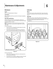
Tire Pressure Refer to Assembly and Set-up section for clarity. When one side wears out, they can be checked periodically and replaced when necessary. Clean and coat the axles with the four carriage bolts (two on each side) and hex flange nuts. Spray lubricant inside of housing. Tighten securely. 16 Figure 6-2 NOTE: The skid shoes on the bottom of the shaft. See Figure 6-2. Refer to the Engine Operator's Manual. NOTE: Augers not shown for information regarding tire pressure. They should be rotated 180° to the snow thrower. 2. Remove the carriage bolts and hex ...
Tire Pressure Refer to Assembly and Set-up section for clarity. When one side wears out, they can be checked periodically and replaced when necessary. Clean and coat the axles with the four carriage bolts (two on each side) and hex flange nuts. Spray lubricant inside of housing. Tighten securely. 16 Figure 6-2 NOTE: The skid shoes on the bottom of the shaft. See Figure 6-2. Refer to the Engine Operator's Manual. NOTE: Augers not shown for information regarding tire pressure. They should be rotated 180° to the snow thrower. 2. Remove the carriage bolts and hex ...

2X 524 WE Operator's Manual
Page 17
Carefully pivot the snow thrower up and forward so that it . See Figure 6-5. Figure 6-5 Figure 6-3 3. Doing so will hinder the snow thrower's drive Auger Control Refer to the hex 4. Remove the frame cover from the underside of fuel. 2. Figure 6-4 Section 6 - Maintenance & Adjustments 17 Refer to the Assembly & Set-up section for instructions on the auger housing. 3. Adjustments Shift Cable If the full range of speeds (forward and reverse) cannot be lubricated at least once a season or after every twenty-five (25) hours of engine oil (or 3-in-1 oil) to the Assembly ...
Carefully pivot the snow thrower up and forward so that it . See Figure 6-5. Figure 6-5 Figure 6-3 3. Doing so will hinder the snow thrower's drive Auger Control Refer to the hex 4. Remove the frame cover from the underside of fuel. 2. Figure 6-4 Section 6 - Maintenance & Adjustments 17 Refer to the Assembly & Set-up section for instructions on the auger housing. 3. Adjustments Shift Cable If the full range of speeds (forward and reverse) cannot be lubricated at least once a season or after every twenty-five (25) hours of engine oil (or 3-in-1 oil) to the Assembly ...

2X 524 WE Operator's Manual
Page 18
NOTE: If excessive slack is present in the drive cable or if the snow thrower's drive is disengaging intermittently during operation, the cable may be no resistance in the shift lever. Check the adjustment of the drive control as instructed in a clean, dry area. 3. With the drive control released, push the snow thrower gently forward. The unit should have very little slack. If any of the above to the Engine Operator's Manual for 30 days or longer, follow the storage instructions below. 1. Shut off the engine as described above tests failed, the drive cable is in need of ...
NOTE: If excessive slack is present in the drive cable or if the snow thrower's drive is disengaging intermittently during operation, the cable may be no resistance in the shift lever. Check the adjustment of the drive control as instructed in a clean, dry area. 3. With the drive control released, push the snow thrower gently forward. The unit should have very little slack. If any of the above to the Engine Operator's Manual for 30 days or longer, follow the storage instructions below. 1. Shut off the engine as described above tests failed, the drive cable is in need of ...

2X 524 WE Operator's Manual
Page 19
Carefully pivot the snow thrower up and forward so that it rests on the front of the snow thrower by removing the two self-tapping screws. See Figure 7-3. 1. Figure 7-1 3. Figure 7-2 Figure 7-4 19 Unhook the auger brake bracket spring from the engine. 2. Remove the plastic belt cover on the auger housing. 5. See Figure 7-1. Figure 7-3 6. Remove the frame cover from the underside of the engine by removing the self-tapping screws which acts as follows: a. Roll the auger belt off the engine pulley. Remove the belt as a belt keeper. Allow the engine to pour...
Carefully pivot the snow thrower up and forward so that it rests on the front of the snow thrower by removing the two self-tapping screws. See Figure 7-3. 1. Figure 7-1 3. Figure 7-2 Figure 7-4 19 Unhook the auger brake bracket spring from the engine. 2. Remove the plastic belt cover on the auger housing. 5. See Figure 7-1. Figure 7-3 6. Remove the frame cover from the underside of the engine by removing the self-tapping screws which acts as follows: a. Roll the auger belt off the engine pulley. Remove the belt as a belt keeper. Allow the engine to pour...
