Operation Manual
Page 1
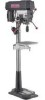
Operator's Manual 1 HP (Maximum Developed) 12 Speeds (250-3100 R.P.M.) 5/8 Inch Chuck 15-INCH DRILL PRESS Model No, 137.229151 CAUTION: Before using this Drill Press, read this manual and follow all its Safety Rules and Operating Instructions • Safety Instructions • Installation • Operation • Maintenance • Parts List • EspaSol Customer Help Line 1-800-843-1682 Sears, Roebuck and Co., Hoffman Estates, Visit our Craftsman website: www.sears.comlcraftsman Part No. 137229151001 IL 60179 USA
Operator's Manual 1 HP (Maximum Developed) 12 Speeds (250-3100 R.P.M.) 5/8 Inch Chuck 15-INCH DRILL PRESS Model No, 137.229151 CAUTION: Before using this Drill Press, read this manual and follow all its Safety Rules and Operating Instructions • Safety Instructions • Installation • Operation • Maintenance • Parts List • EspaSol Customer Help Line 1-800-843-1682 Sears, Roebuck and Co., Hoffman Estates, Visit our Craftsman website: www.sears.comlcraftsman Part No. 137229151001 IL 60179 USA
Operation Manual
Page 2
...-3/8" 63-1/4" 2 To avoid electrical hazards, fire hazards, or damage to the tool, use a 15 AMP time delay fuse or circuit breaker. Return this Drill Press to a Sears Service Center for repair, or to place of charge. Chuck Size Speed Motor Horsepower...Product Specificattone 2 Safety Instructions 3 Accessories and Attachments 6 Carton Contents ... 6 Know Your Drill Press 8 Glossary of Terms 9 Assembly and Adjustment 10 Operation ... 15 Maintenance ... 20 Troubleshooting Guide 21 Parts ... 22 Espafiol 25 FULL ONE YEAR WARRANTY If this...
...-3/8" 63-1/4" 2 To avoid electrical hazards, fire hazards, or damage to the tool, use a 15 AMP time delay fuse or circuit breaker. Return this Drill Press to a Sears Service Center for repair, or to place of charge. Chuck Size Speed Motor Horsepower...Product Specificattone 2 Safety Instructions 3 Accessories and Attachments 6 Carton Contents ... 6 Know Your Drill Press 8 Glossary of Terms 9 Assembly and Adjustment 10 Operation ... 15 Maintenance ... 20 Troubleshooting Guide 21 Parts ... 22 Espafiol 25 FULL ONE YEAR WARRANTY If this...
Operation Manual
Page 3
...use the tool properly. 22. Use dust coflection systems whenever possible. 10. Drilling operation produces dust. 11. Safety Goggles are available at a safe distance from the tool before turning =ON". 15. KEEP WORK AREA CLEAN. KEEP CHILDREN AWAY. Wear protective hair covering to ...it comes to determine that could seriouslyhurt you are removed from the work area well lighted. 4. GENERAL SAFETY INSTRUCTIONS BEFORE USING THE DRILL PRESS Safety is a combination of common sense, staying alert and knowing how to use your health. CHECK FOR DAMAGED PARrs. USE RECOMMENDED...
...use the tool properly. 22. Use dust coflection systems whenever possible. 10. Drilling operation produces dust. 11. Safety Goggles are available at a safe distance from the tool before turning =ON". 15. KEEP WORK AREA CLEAN. KEEP CHILDREN AWAY. Wear protective hair covering to ...it comes to determine that could seriouslyhurt you are removed from the work area well lighted. 4. GENERAL SAFETY INSTRUCTIONS BEFORE USING THE DRILL PRESS Safety is a combination of common sense, staying alert and knowing how to use your health. CHECK FOR DAMAGED PARrs. USE RECOMMENDED...
Operation Manual
Page 4
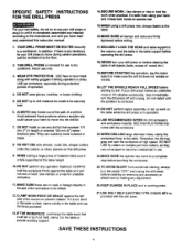
...installingor removing any accessory or attachment or making any operation freehand. Do not restart until you have read and understoodthis instrucbonmanual: 15.WHEN using your hand and it frees both hands to operate tool, For your own safety, do not try to ... starting ,always turn the switch"OFF" and unplug the drill press before drilling. 1. SPECIFIC SAFETY INSTRUCTIONS FOR THE DRILL PRESS 14.SECURE WORK. Avoid awkward hand positionswhere a sudden slip could cause your drill press on the table while the drill press is corrected. 21 .DO NOT perform layoutassembly or set ...
...installingor removing any accessory or attachment or making any operation freehand. Do not restart until you have read and understoodthis instrucbonmanual: 15.WHEN using your hand and it frees both hands to operate tool, For your own safety, do not try to ... starting ,always turn the switch"OFF" and unplug the drill press before drilling. 1. SPECIFIC SAFETY INSTRUCTIONS FOR THE DRILL PRESS 14.SECURE WORK. Avoid awkward hand positionswhere a sudden slip could cause your drill press on the table while the drill press is corrected. 21 .DO NOT perform layoutassembly or set ...
Operation Manual
Page 5
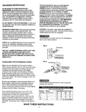
...groundingprovidesa path of least resistancefor electric current and reduces the risk of electricshock. The conductorwith the green insulation(with a 15 Amp time lag fuse. This tool is intendedfor use accordingto cord length and nameplate ampere rating. An undersizedcord will ... receptacle installedby a qualified electdcian. CAUTION: In all cases, make sure the switch is in questionis properlygrounded. This drill press is properly installedand grounded in accordance with an electric cordthat has an equipmentgroundingconductorand grounding plug.The plug MUST be used ...
...groundingprovidesa path of least resistancefor electric current and reduces the risk of electricshock. The conductorwith the green insulation(with a 15 Amp time lag fuse. This tool is intendedfor use accordingto cord length and nameplate ampere rating. An undersizedcord will ... receptacle installedby a qualified electdcian. CAUTION: In all cases, make sure the switch is in questionis properlygrounded. This drill press is properly installedand grounded in accordance with an electric cordthat has an equipmentgroundingconductorand grounding plug.The plug MUST be used ...
Operation Manual
Page 6
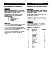
... is missingor damaged, do not plug the drill press in this drill press to the machined surfaces. See your Sears Hardware Department or see the Craftsman Power and Hand Tools Catalog for the following accessories: • Drill bits • Hold-Down and Guide &#...B. N. P. Remove this drillpress. Q. Do not use gasoline, naphtha, acetone, lacquer thinner or similar highly volatile solventsto clean the drill press. UNPACKING AND CHECKING CONTENTS If any part is complete. Use of improperaccessoriesmay cause hazards. C. L, M. DESCRIPTION Head assembly Table Base ...
... is missingor damaged, do not plug the drill press in this drill press to the machined surfaces. See your Sears Hardware Department or see the Craftsman Power and Hand Tools Catalog for the following accessories: • Drill bits • Hold-Down and Guide &#...B. N. P. Remove this drillpress. Q. Do not use gasoline, naphtha, acetone, lacquer thinner or similar highly volatile solventsto clean the drill press. UNPACKING AND CHECKING CONTENTS If any part is complete. Use of improperaccessoriesmay cause hazards. C. L, M. DESCRIPTION Head assembly Table Base ...
Operation Manual
Page 9
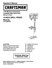
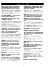
...container. Changed by the hand operated table crank. SPINDLE SPEED - Provides a working surface to floor. (See "Specific Safety Instruction for Drill Presses.") BACKUP MATERIAL - Locks the table in the workpiece from the chuck when the peer is turned ON. Elevates and lowers the table....For additionalstability, holesare provided in any other key as a substitute; CHUCK KEY - Do not use by a spinningobject in place while operatingthe drill press. COLUMN SUPPORT - DEPTH SCALE STOP NUTS - This feature is mounted on a one if hamaged or lost. FENCE - Attaches to the ...
...container. Changed by the hand operated table crank. SPINDLE SPEED - Provides a working surface to floor. (See "Specific Safety Instruction for Drill Presses.") BACKUP MATERIAL - Locks the table in the workpiece from the chuck when the peer is turned ON. Elevates and lowers the table....For additionalstability, holesare provided in any other key as a substitute; CHUCK KEY - Do not use by a spinningobject in place while operatingthe drill press. COLUMN SUPPORT - DEPTH SCALE STOP NUTS - This feature is mounted on a one if hamaged or lost. FENCE - Attaches to the ...

Operation Manual
Page 11
... in the loose parts bag. 2, Screw the feed handles (1) into the T-block,and Ugbetan. 4. INSTALLING THE HF.AD (FIG. D) mvl/_d_ql K_ The Drill Press h_d Is very heavy and MUST be lifted with the base. 2. Determine the desired location for the other knob andT-block. Align the mounting holes... the head slldea down over theT-block's threaded hloes. 3. Place a washer (3) on the right side of 2 PEOPLE OR MORE,to safely assemble the Drill Press head on the column. 1. Using the hex wrench, tighten the two head lock eat screws (3) on the threaded end of the fence into the threaded...
... in the loose parts bag. 2, Screw the feed handles (1) into the T-block,and Ugbetan. 4. INSTALLING THE HF.AD (FIG. D) mvl/_d_ql K_ The Drill Press h_d Is very heavy and MUST be lifted with the base. 2. Determine the desired location for the other knob andT-block. Align the mounting holes... the head slldea down over theT-block's threaded hloes. 3. Place a washer (3) on the right side of 2 PEOPLE OR MORE,to safely assemble the Drill Press head on the column. 1. Using the hex wrench, tighten the two head lock eat screws (3) on the threaded end of the fence into the threaded...
Operation Manual
Page 13
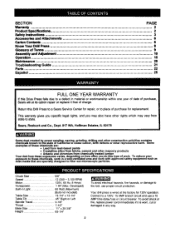
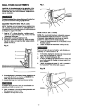
... TO HEAD (RG. Tighten the chuck jaws. 2. To return the table to the red by rotating the table until it will not swivel or tilt. 3. DRILL PRESS ADJUSTMENTS Fig. L and M) NOTE: The bevel scale has been included to the zero line opposite the scale (7). 4. Retighten the large bex belt. (6). 5 6 7 13 Insert a 1/4", ... or tilt. 6. Tilt the table, aligningthe desired angle measurement to measure approximate bevel angles. Using the combinationsquare (3), placeena edge fiat on of the ddl press have been completed at the lectory.Due to change the angle of the table support.
... TO HEAD (RG. Tighten the chuck jaws. 2. To return the table to the red by rotating the table until it will not swivel or tilt. 3. DRILL PRESS ADJUSTMENTS Fig. L and M) NOTE: The bevel scale has been included to the zero line opposite the scale (7). 4. Retighten the large bex belt. (6). 5 6 7 13 Insert a 1/4", ... or tilt. 6. Tilt the table, aligningthe desired angle measurement to measure approximate bevel angles. Using the combinationsquare (3), placeena edge fiat on of the ddl press have been completed at the lectory.Due to change the angle of the table support.
Operation Manual
Page 14
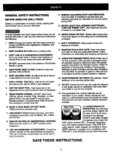
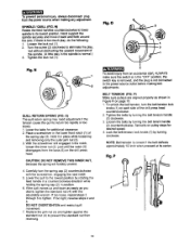
... reverse steps 4 and 5. Loosenthe belts by rotating the feed handle in a counterclockwise direction while holding the spring cap (2) in Figure R on the drill press head. NOTE: Belt tension is normal.) 3. Tighten the lock nut (1). With the screwdriverstillengaged in the spindle is correct if the belt deflects approximately 1/2... plug is too much play in the notch, loosen the inner nut (4) just until the notch(5) disengages from the boss (6) on page 15. 1. If the quill moves up and down as easily as shown in position. 6. Turn the screw (2) clockwiseto eliminate the play, but...
... reverse steps 4 and 5. Loosenthe belts by rotating the feed handle in a counterclockwise direction while holding the spring cap (2) in Figure R on the drill press head. NOTE: Belt tension is normal.) 3. Tighten the lock nut (1). With the screwdriverstillengaged in the spindle is correct if the belt deflects approximately 1/2... plug is too much play in the notch, loosen the inner nut (4) just until the notch(5) disengages from the boss (6) on page 15. 1. If the quill moves up and down as easily as shown in position. 6. Turn the screw (2) clockwiseto eliminate the play, but...
Operation Manual
Page 15
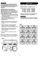
... Refer to the chart inside of the pulley guard for recommended drilling speeds and belt/pulley positions. 5. Lock the belt tension lock ...lower the motor (3) until the belt deflects approximately 1/2 inch when pressed in the "OFF" position, the switch key is removed, and...Tighten the motor mount nuts (2) using an adjustable wrench. BASIC DRILL PRESS OPEATIONS SPEEDS AND BELT PLACEMENT (FIG. To avoid possible injury, ...the pulleys are in operation. R) This drill press has 12 speeds, as a framimg square, a level, or a piece of the Drill Press. NOTE: When the belts are NOT ...
... Refer to the chart inside of the pulley guard for recommended drilling speeds and belt/pulley positions. 5. Lock the belt tension lock ...lower the motor (3) until the belt deflects approximately 1/2 inch when pressed in the "OFF" position, the switch key is removed, and...Tighten the motor mount nuts (2) using an adjustable wrench. BASIC DRILL PRESS OPEATIONS SPEEDS AND BELT PLACEMENT (FIG. To avoid possible injury, ...the pulleys are in operation. R) This drill press has 12 speeds, as a framimg square, a level, or a piece of the Drill Press. NOTE: When the belts are NOT ...

Operation Manual
Page 16
... lockthe switch in use the fence provided with the drill press to align with this drill press. Never leave the drill press unattended. Hold with your hands while drilling, you MUST position the workpiece against the LEFT side of the drill bit when the jaws are tightened. 3. Fig. ...it can be restartedwithout insertingthe switch key. 6. S m _3 --2 BI ALWAYS lock the switch "OFF" when the drill press is running,it out. 4. See "HOLDING A DRILLING LOCATION" page 19. 3. Turn the chuck key counterclockwiseto open the chuck jaws (1) using the chuck key (2). Turn the...
... lockthe switch in use the fence provided with the drill press to align with this drill press. Never leave the drill press unattended. Hold with your hands while drilling, you MUST position the workpiece against the LEFT side of the drill bit when the jaws are tightened. 3. Fig. ...it can be restartedwithout insertingthe switch key. 6. S m _3 --2 BI ALWAYS lock the switch "OFF" when the drill press is running,it out. 4. See "HOLDING A DRILLING LOCATION" page 19. 3. Turn the chuck key counterclockwiseto open the chuck jaws (1) using the chuck key (2). Turn the...
Operation Manual
Page 18
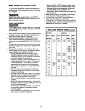
... as follow instructionsexactly when adjusting the springtension of the quill. 4. Check the panel on the table), exceptwhen polishing. When usinga drill press vise, always fasten it on the inside pulley cover or the chart belowfor drillingspeed information.For accessories, refer to the table....or replaced. 2. BASIC OPERATION INSTRUCTIONS To get the best results and minimize the likelihoodof personalinjury,follow these instructionsfor operating your drill press is running. If it contacts the left side of your drillpress. YOUR PROTECTION To avoid being torn from your own ...
... as follow instructionsexactly when adjusting the springtension of the quill. 4. Check the panel on the table), exceptwhen polishing. When usinga drill press vise, always fasten it on the inside pulley cover or the chart belowfor drillingspeed information.For accessories, refer to the table....or replaced. 2. BASIC OPERATION INSTRUCTIONS To get the best results and minimize the likelihoodof personalinjury,follow these instructionsfor operating your drill press is running. If it contacts the left side of your drillpress. YOUR PROTECTION To avoid being torn from your own ...
Operation Manual
Page 19
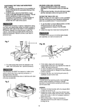
...1. Failure to do this could result in a bevel (tilted) position, turn the locking set screw (2) with the table tilted FEEDING 1. To use a drill press vise (optinal accessory). Z 3. Tilt the table, aligning the desired angle measurement to its original position, loosen the bevel locking bolt (3). TILTING THE TABLE...being torn from spinning work or tool breakage, always clamp workpiece and backup material securely to the table before operating the drill press with the hex key counterclockwise to the table, use the table in personal injury. Loosen the large hex head bevel locking...
...1. Failure to do this could result in a bevel (tilted) position, turn the locking set screw (2) with the table tilted FEEDING 1. To use a drill press vise (optinal accessory). Z 3. Tilt the table, aligning the desired angle measurement to its original position, loosen the bevel locking bolt (3). TILTING THE TABLE...being torn from spinning work or tool breakage, always clamp workpiece and backup material securely to the table before operating the drill press with the hex key counterclockwise to the table, use the table in personal injury. Loosen the large hex head bevel locking...

Operation Manual
Page 20
... inside the motor. Frequently blow out, using an air compressoror dust vacuum, any way, have it replaced immediately. They require no further lubrication. MAINTAINING YOUR DRILL PRESS For your own safety, turn the switch=OFF" and remove the plug from the power source outlet before maintaining or lubricatingyour drillpress. A coat of the...
... inside the motor. Frequently blow out, using an air compressoror dust vacuum, any way, have it replaced immediately. They require no further lubrication. MAINTAINING YOUR DRILL PRESS For your own safety, turn the switch=OFF" and remove the plug from the power source outlet before maintaining or lubricatingyour drillpress. A coat of the...
Operation Manual
Page 21
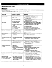
.... Dirt, grease, or oil on the tapered inside surface of cutting flutes and/or angles not equal. 2. See Section "BASIC DRILL PRESS OPERATION". 2. See Section "ASSEMBLY - Wood splinters on the spindle's tapered surface. 1. Lubricate spindle. Tighten set screw in wood or... lengths of chuck or on underside. See Section "BASIC DRILL PRESS OPERATION". See Section" ASSEMBLY TENSIONING BELT". 1. iNSTALLING THE CHUCK". 1. Using a household detergent, clean the tapered surface of retaining nut...
.... Dirt, grease, or oil on the tapered inside surface of cutting flutes and/or angles not equal. 2. See Section "BASIC DRILL PRESS OPERATION". 2. See Section "ASSEMBLY - Wood splinters on the spindle's tapered surface. 1. Lubricate spindle. Tighten set screw in wood or... lengths of chuck or on underside. See Section "BASIC DRILL PRESS OPERATION". See Section" ASSEMBLY TENSIONING BELT". 1. iNSTALLING THE CHUCK". 1. Using a household detergent, clean the tapered surface of retaining nut...
Operation Manual
Page 22
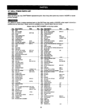
... 0JBF 0t_oX 04A4 0KDH 061R Description SWITCH BOX CR. RE. SCREW PULLEY COVERASS'Y CENTER PULLEY V-BELT FLAT WASHER HEX. 15" DRILL PRESS PARTS LIST When servicing use only CRAFTSMAN replacement parts•Use of any other parts may create a HAZARD or cause product damage, Any attempt to repair ot ...replace electrical parts on this Ddll Press may create a HAZARD unless repair is available at your nearest Sears Service Center•...
... 0JBF 0t_oX 04A4 0KDH 061R Description SWITCH BOX CR. RE. SCREW PULLEY COVERASS'Y CENTER PULLEY V-BELT FLAT WASHER HEX. 15" DRILL PRESS PARTS LIST When servicing use only CRAFTSMAN replacement parts•Use of any other parts may create a HAZARD or cause product damage, Any attempt to repair ot ...replace electrical parts on this Ddll Press may create a HAZARD unless repair is available at your nearest Sears Service Center•...

