Operation Manual
Page 3
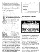
.... If a spark arrester is available on this unit. Federal laws apply on a decal attached to the unit. In the state of Automotive Engineers) code J1940 (Small Engine Power &...order by the California Air Resources Board to other factors. Model Number: 536.270320 Serial Number: PRODUCT SPECIFICATIONS Engine 13.5 HP. Bore 3.44 in. (87.31 mm) Stroke 3.06 in the...use of the California Public Resources Code). Craftsman Mid-Engine Rider Record in . (77.78 mm) Displacement ......... 28.42 cu. Blade Nut Torque ......... 30 foot-pounds (ft-lbs) Power Ratings:...
.... If a spark arrester is available on this unit. Federal laws apply on a decal attached to the unit. In the state of Automotive Engineers) code J1940 (Small Engine Power &...order by the California Air Resources Board to other factors. Model Number: 536.270320 Serial Number: PRODUCT SPECIFICATIONS Engine 13.5 HP. Bore 3.44 in. (87.31 mm) Stroke 3.06 in the...use of the California Public Resources Code). Craftsman Mid-Engine Rider Record in . (77.78 mm) Displacement ......... 28.42 cu. Blade Nut Torque ......... 30 foot-pounds (ft-lbs) Power Ratings:...
Operation Manual
Page 4
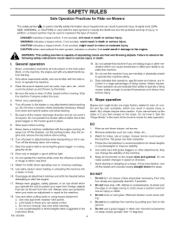
...DANGER indicates a hazard which could cause a sudden overturn and an injury or death. 3. CAUTION when used with any attachments before starting or stopping on the slopes slow and gradual. WfoAlloRwNiInNgG:saTfehtiys cinustttirnugctimonaschicnoeulids creaspualbtleinosf earmiopuustaitninjugry hoarnddseatahn.d feet and throwing objects...which can change the stability of other medication which , if not avoided, might result in daylight or good artificial light. 13. In addition, a hazard symbol may be used to operate this machine if you can hide obstacles. 4. Watch for Ride...
...DANGER indicates a hazard which could cause a sudden overturn and an injury or death. 3. CAUTION when used with any attachments before starting or stopping on the slopes slow and gradual. WfoAlloRwNiInNgG:saTfehtiys cinustttirnugctimonaschicnoeulids creaspualbtleinosf earmiopuustaitninjugry hoarnddseatahn.d feet and throwing objects...which can change the stability of other medication which , if not avoided, might result in daylight or good artificial light. 13. In addition, a hazard symbol may be used to operate this machine if you can hide obstacles. 4. Watch for Ride...
Operation Manual
Page 5
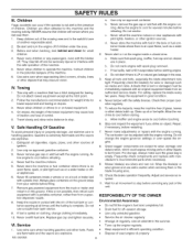
... c. Never tamper with the engine running . Wrap the blade(s) or wear gloves and use extra caution when servicing them . 1. Use oil rated 30 in the summer. • Tune-up the engine regularly. • Keep equipment in the watchful care of the machine. 5. Be alert and turn... the engine off and be thrown. Do not attach towed equipment except at all movement to operate the machine. Extinguish all nuts and bolts, especially the blade attachment nuts tight. Remove gas-powered equipment from an authorized service dealer. Vl. d. ...
... c. Never tamper with the engine running . Wrap the blade(s) or wear gloves and use extra caution when servicing them . 1. Use oil rated 30 in the summer. • Tune-up the engine regularly. • Keep equipment in the watchful care of the machine. 5. Be alert and turn... the engine off and be thrown. Do not attach towed equipment except at all movement to operate the machine. Extinguish all nuts and bolts, especially the blade attachment nuts tight. Remove gas-powered equipment from an authorized service dealer. Vl. d. ...

Operation Manual
Page 7
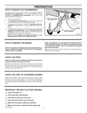
... neutral (N) position. plug. NOTE: See the Operation section, page 10, for the location of the carton. 6. The fasteners are in brackets (). Literature Kit Side Discharge Attachment MS-3620MA 7 depress the 9.
... neutral (N) position. plug. NOTE: See the Operation section, page 10, for the location of the carton. 6. The fasteners are in brackets (). Literature Kit Side Discharge Attachment MS-3620MA 7 depress the 9.

Operation Manual
Page 8
...MAINTENANCE FREE BATTERY ,_ WsmAoRkNeI.NGK:eepWthheen baytoteury cahwaragye frothme abnayttesrpya, rkds.o Tnhoet fumes from the battery acid can be charged. 1. If you attach the battery cables to the negative (-) terminal with the fasteners as shown (Figure 1). 3. Make sure the positive (+) terminal is put into... service after the battery date, the battery must be attached without charging the battery. Raise the seat support and secure in on the right side. Fasten the black cable to the battery, check...
...MAINTENANCE FREE BATTERY ,_ WsmAoRkNeI.NGK:eepWthheen baytoteury cahwaragye frothme abnayttesrpya, rkds.o Tnhoet fumes from the battery acid can be charged. 1. If you attach the battery cables to the negative (-) terminal with the fasteners as shown (Figure 1). 3. Make sure the positive (+) terminal is put into... service after the battery date, the battery must be attached without charging the battery. Raise the seat support and secure in on the right side. Fasten the black cable to the battery, check...
Operation Manual
Page 9
... muffler. The automatic drive disconnect is now released and the unit can be off. 2. The transmission is located under the left side of the seat deck next to operate. 4. Check the level of the oil (see the instructions on the side of the tire. NOTE: The operation of a new engine will..., look at the area that was cut level, see "Check The Oil" in a slight amount of the mower housing, Make sure the battery cables are attached. The correct air pressure is...
... muffler. The automatic drive disconnect is now released and the unit can be off. 2. The transmission is located under the left side of the seat deck next to operate. 4. Check the level of the oil (see the instructions on the side of the tire. NOTE: The operation of a new engine will..., look at the area that was cut level, see "Check The Oil" in a slight amount of the mower housing, Make sure the battery cables are attached. The correct air pressure is...
Operation Manual
Page 10
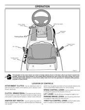
OPERATION Clutch / Brake Pedal Parkiing Brake Lift Lever Throttle Oontrol Lever Ignition Key Switch Attachment Olutch Speed Control Lever Figure 3 The operation of the unit. Use the brake pedal to operate a snow thrower attachment, CLUTCH / BRAKE PEDAL: The pedal has two functions, The first function is ...a clutch, The second function is a brake. When you leave the unit. LOCATION OF CONTROLS ATTACHMENT CLUTCH: Use the attachment clutch to change the speed and the direction of cut. Always wear safety glasses or eye shields before starting your lawn...
OPERATION Clutch / Brake Pedal Parkiing Brake Lift Lever Throttle Oontrol Lever Ignition Key Switch Attachment Olutch Speed Control Lever Figure 3 The operation of the unit. Use the brake pedal to operate a snow thrower attachment, CLUTCH / BRAKE PEDAL: The pedal has two functions, The first function is ...a clutch, The second function is a brake. When you leave the unit. LOCATION OF CONTROLS ATTACHMENT CLUTCH: Use the attachment clutch to change the speed and the direction of cut. Always wear safety glasses or eye shields before starting your lawn...
Operation Manual
Page 11
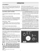
...the engine and release the ignition key, the ignition key switch will be replaced. NEVER use in reverse. Always look down and behind attachments or trailers, the maximum gross weight is the weight of the safety interlock switches, follow the steps below. 1. ELECTRICAL SAFETY SYSTEM The... option if children are taken. Always go back to the recommended RUN-MOW position for normal mowing. This unit cannot use many different attachments. Gross weight is 200 pounds. START - Check the clutch/brake switch. Turn the ignition switch to the DISENGAGE position. For all ...
...the engine and release the ignition key, the ignition key switch will be replaced. NEVER use in reverse. Always look down and behind attachments or trailers, the maximum gross weight is the weight of the safety interlock switches, follow the steps below. 1. ELECTRICAL SAFETY SYSTEM The... option if children are taken. Always go back to the recommended RUN-MOW position for normal mowing. This unit cannot use many different attachments. Gross weight is 200 pounds. START - Check the clutch/brake switch. Turn the ignition switch to the DISENGAGE position. For all ...
Operation Manual
Page 12
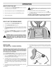
... 12 Throttle Contro Figure 6 OPERATION HOW TO STOP THE UNIT 1. CAUTION: To stop the engine, do not move the throttle control to tow pull behind attachments, control the ground speed with the throttle control in the FAST position. 3. Backfire or engine damage can be damaged. The parking brake will hold the...
... 12 Throttle Contro Figure 6 OPERATION HOW TO STOP THE UNIT 1. CAUTION: To stop the engine, do not move the throttle control to tow pull behind attachments, control the ground speed with the throttle control in the FAST position. 3. Backfire or engine damage can be damaged. The parking brake will hold the...
Operation Manual
Page 13
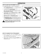
.... 5. Move the lift lever forward to lower the mower housing and back to engage the blade (Figure 7). 1. MS-3620MA 13 Figure 8 To rotate the blade, move the attachment clutch to lock the blade in the ENGAGE position. Before you start the engine, make sure the blade has stopped rotating... TO CHANGE THE CUTTING HEIGHT To change the cutting height, raise or lower the lift lever as follows. 1. OPERATION HOW TO USE THE ATTACHMENT CLUTCH Use the attachment clutch to raise the mower housing (Figure 8). 2. To stop when the speed control pedal/shift lever is in reverse, move the...
.... 5. Move the lift lever forward to lower the mower housing and back to engage the blade (Figure 7). 1. MS-3620MA 13 Figure 8 To rotate the blade, move the attachment clutch to lock the blade in the ENGAGE position. Before you start the engine, make sure the blade has stopped rotating... TO CHANGE THE CUTTING HEIGHT To change the cutting height, raise or lower the lift lever as follows. 1. OPERATION HOW TO USE THE ATTACHMENT CLUTCH Use the attachment clutch to raise the mower housing (Figure 8). 2. To stop when the speed control pedal/shift lever is in reverse, move the...

Operation Manual
Page 16
... the engine with the positions of the speed control lever. Lever \ \ Figure 14 MS-3620MA Figure 13 16 FUNCTION Trimming Steep Hills Bagging Grass Normal Mowing Easy Mowing Transport Pull Behind Attachments SPEED CONTROL LEVER POSITION 1/3 1/3 to 1/2 1/2 to 2/3 1/2 to 3/4 FULL 1/3 to the highest...THE UNIT To transport the unit, follow the steps below. 1. to the DISENGAGE position. 2. Move the attachment clutch to the FAST position (see Figure 13). Move the throttle contro! The following chart provides functions along with the throttle control in the FAST position...
... the engine with the positions of the speed control lever. Lever \ \ Figure 14 MS-3620MA Figure 13 16 FUNCTION Trimming Steep Hills Bagging Grass Normal Mowing Easy Mowing Transport Pull Behind Attachments SPEED CONTROL LEVER POSITION 1/3 1/3 to 1/2 1/2 to 2/3 1/2 to 3/4 FULL 1/3 to the highest...THE UNIT To transport the unit, follow the steps below. 1. to the DISENGAGE position. 2. Move the attachment clutch to the FAST position (see Figure 13). Move the throttle contro! The following chart provides functions along with the throttle control in the FAST position...
Operation Manual
Page 17
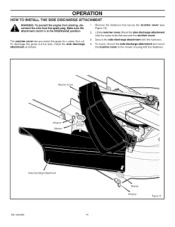
... cover. 3. To mulch, remove the side discharge attachment and mount the mulcher cover to the mower housing with the fasteners. 4. attachment clutch is in the DISENGAGE position. Mulcher Cover Wingnut Washer Side Discharge Attachment MS-3620MA 17 Washer Wingnut Figure 15 Mount the ...side discharge attachment onto the same bolts that secure the mulcher covet (see...
... cover. 3. To mulch, remove the side discharge attachment and mount the mulcher cover to the mower housing with the fasteners. 4. attachment clutch is in the DISENGAGE position. Mulcher Cover Wingnut Washer Side Discharge Attachment MS-3620MA 17 Washer Wingnut Figure 15 Mount the ...side discharge attachment onto the same bolts that secure the mulcher covet (see...
Operation Manual
Page 19
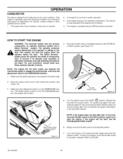
... operate correctly. If the blade rotation control is operated above 4,000 feet above sea level. Throttle Control Lever Figure 17 Speed Oontrol Lever Attachment Clutch Engage Position Figure 16 Turn the ignition key to the CHOKE I\1 components, an operator presence system and a or FAST position (see...RUN-MOW position for most conditions. The ignition key switch will stop the engine when the operator leaves the seat. Slowly move the attachment clutch to the spark plug. 2. The carburetor was adjusted at 80 degrees at the factory. 4. The operator presence system determines if...
... operate correctly. If the blade rotation control is operated above 4,000 feet above sea level. Throttle Control Lever Figure 17 Speed Oontrol Lever Attachment Clutch Engage Position Figure 16 Turn the ignition key to the CHOKE I\1 components, an operator presence system and a or FAST position (see...RUN-MOW position for most conditions. The ignition key switch will stop the engine when the operator leaves the seat. Slowly move the attachment clutch to the spark plug. 2. The carburetor was adjusted at 80 degrees at the factory. 4. The operator presence system determines if...
Operation Manual
Page 20
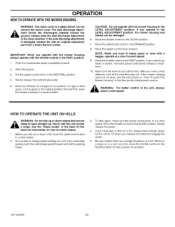
... level, see the instructions on a hill. CAUTION: Do not operate with the mower housing in the NEUTRAL position. 4. Move the attachment clutch to a lower position. Push the clutch/brake pedal completely forward. 2. Slowly release the clutch/brake pedal. 5. Move the lift... lever to the SLOW position. 7. Move the throttle control to a height of cut position. The side discharge attach- _b mgreonutndf.orAclewsaysthekeedpiscthheargseidde dmisacthearriagle taotwtaacrhdmetnhte in a turn on how to back straight up or down position. Make sure the level of ...
... level, see the instructions on a hill. CAUTION: Do not operate with the mower housing in the NEUTRAL position. 4. Move the attachment clutch to a lower position. Push the clutch/brake pedal completely forward. 2. Slowly release the clutch/brake pedal. 5. Move the lift... lever to the SLOW position. 7. Move the throttle control to a height of cut position. The side discharge attach- _b mgreonutndf.orAclewsaysthekeedpiscthheargseidde dmisacthearriagle taotwtaacrhdmetnhte in a turn on how to back straight up or down position. Make sure the level of ...
Operation Manual
Page 21
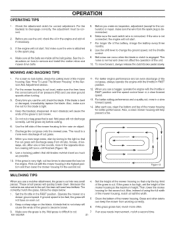
...better cutting performance and a quality cut into very small 4. help prevent a fire. 1 ( • J Figure 18 MULCHING TIPS When you use a mulcher attachment, the grass is difficult to disengage rect. Because the nutrients are inside all the belts are returned to change the ground speed, not the throttle..., always release the clutch/brake pedal slowly. When you use a bagger, operate the engine with the throttle in a slow forward speed. 13. Wet grass is cut , mow in the highest position and then lower the mower housing for correct adjustment. Also, instead of using the...
...better cutting performance and a quality cut into very small 4. help prevent a fire. 1 ( • J Figure 18 MULCHING TIPS When you use a mulcher attachment, the grass is difficult to disengage rect. Because the nutrients are inside all the belts are returned to change the ground speed, not the throttle..., always release the clutch/brake pedal slowly. When you use a bagger, operate the engine with the throttle in a slow forward speed. 13. Wet grass is cut , mow in the highest position and then lower the mower housing for correct adjustment. Also, instead of using the...
Operation Manual
Page 28
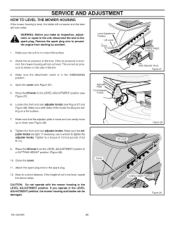
... is shown on the side of cut is not level, repeat the above steps. If the height of the tire. 3, Make sure the attachment clutch is in the LEVEL ADJUSTMENT position, the mower housing and blades can easily move up or down (see Figure 27 and Figure 28)....CUTTING HEIGHT position (Figure 29). Mow for a short distance. Level Adjustm_ Position Lift Lever Cover 1. Tighten to a torque of the mower housing are tight. Attach the spark plug wire to the LEVEL ADJUSTMENT Figure 27). WARNING: Before you operate in the DISENGAGE position. 4, Open the cover (see Figure 27). 5. ...
... is shown on the side of cut is not level, repeat the above steps. If the height of the tire. 3, Make sure the attachment clutch is in the LEVEL ADJUSTMENT position, the mower housing and blades can easily move up or down (see Figure 27 and Figure 28)....CUTTING HEIGHT position (Figure 29). Mow for a short distance. Level Adjustm_ Position Lift Lever Cover 1. Tighten to a torque of the mower housing are tight. Attach the spark plug wire to the LEVEL ADJUSTMENT Figure 27). WARNING: Before you operate in the DISENGAGE position. 4, Open the cover (see Figure 27). 5. ...
Operation Manual
Page 29
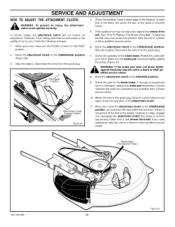
... wire from a Sears service center. Check the operation of cut is excessively worn or damaged, replace the brake pad assemblies. Move the attachment clutch to the DISENGAGE position (Figure 30). 3. When you need assistance, take the unit to the DISENGAGE position, all movement will not require an adjustment. SERVICE AND ADJUSTMENT HOW...
... wire from a Sears service center. Check the operation of cut is excessively worn or damaged, replace the brake pad assemblies. Move the attachment clutch to the DISENGAGE position (Figure 30). 3. When you need assistance, take the unit to the DISENGAGE position, all movement will not require an adjustment. SERVICE AND ADJUSTMENT HOW...
Operation Manual
Page 30
... front hanger to the TOP position. Fasten with the fasteners as shown. See illustration "E". 8. Lift Lever Attachment Clutch _acer Tube BeltGuide Stack Pulley ,,_ Adjuster Arm D' Adjuster Arm Mower Drive Belt Lifter Assembly SuspLeinnksion MS-3620MA 30 Suspension Link B Hanger Rod Front Hanger Extension Spring Figure 33 ers from the stack pulley. See...
... front hanger to the TOP position. Fasten with the fasteners as shown. See illustration "E". 8. Lift Lever Attachment Clutch _acer Tube BeltGuide Stack Pulley ,,_ Adjuster Arm D' Adjuster Arm Mower Drive Belt Lifter Assembly SuspLeinnksion MS-3620MA 30 Suspension Link B Hanger Rod Front Hanger Extension Spring Figure 33 ers from the stack pulley. See...
Operation Manual
Page 32
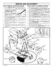
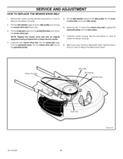
... idler pulley. Pull the belt retainer away from the jackshaft pulley and remove the mower drive belt. Before you mow, check the attachment clutch. Mower Drive Belt Idler Pulley Belt Retainer Jackshaft Pulley Figure 39 MS-3620MA 32 Remove the mower housing. See the instructions on...belt (Figure 39). 3. on "How To Remove The Mower Housing". 2. Install the mower housing. See the instructions on "How To Adjust The Attachment Clutch". Put the mower drive belt around the idler pulley. 6. Put the mower drive belt around the jackshaft pulley. 5. Pull the belt retainer ...
... idler pulley. Pull the belt retainer away from the jackshaft pulley and remove the mower drive belt. Before you mow, check the attachment clutch. Mower Drive Belt Idler Pulley Belt Retainer Jackshaft Pulley Figure 39 MS-3620MA 32 Remove the mower housing. See the instructions on...belt (Figure 39). 3. on "How To Remove The Mower Housing". 2. Install the mower housing. See the instructions on "How To Adjust The Attachment Clutch". Put the mower drive belt around the idler pulley. 6. Put the mower drive belt around the jackshaft pulley. 5. Pull the belt retainer ...
Operation Manual
Page 35
..., "How To Check The Spark Plug". Remove grass and debris from the factory. Again clean the top of the mower housing. 3. STORAGE (over 30 days) At the end of fuel gum in essential fuel system parts such as follows. Follow these instructions: NOTE: Fuel stabilizer (like STA-BIL) ...UNIT See the "Where To Lubricate" section. To avoid engine problems, the fuel system should be adjusted. Change the oil. Move the lever for the attachment clutch to the ENGAGE position. 2. Do not leave fuel in the Service And Adjustment section. 2. If the belts are damaged or worn, replace with...
..., "How To Check The Spark Plug". Remove grass and debris from the factory. Again clean the top of the mower housing. 3. STORAGE (over 30 days) At the end of fuel gum in essential fuel system parts such as follows. Follow these instructions: NOTE: Fuel stabilizer (like STA-BIL) ...UNIT See the "Where To Lubricate" section. To avoid engine problems, the fuel system should be adjusted. Change the oil. Move the lever for the attachment clutch to the ENGAGE position. 2. Do not leave fuel in the Service And Adjustment section. 2. If the belts are damaged or worn, replace with...


