Operation Manual
Page 5
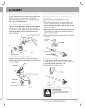
...Shaft Mount Lower Handle Fig. 3 CURVED SHAFT TRIMMERS 1. Cutting Attachment Shield Plate Washer Washer Lock W asher Attaching Screws Fig. 2 D-Handle Fasteners Fig. 4 WARNING: To prevent serious injury, never operate the trimmer without the cutting attachment in desired position. 3. Tighten the screws evenly. Attaching Screws D-Handle Cap Washer Fig. 1 Attaching Screws FOR STRAIGHT SHAFT TRIMMERS.... Installing the D-Handle (non detachable model). 2. LEHR | ALL RIGHTS RESERVED 2008-2009 5 FOR CURVED SHAFT TRIMMERS Place the cutting attachment shield and spacer against tube ...
...Shaft Mount Lower Handle Fig. 3 CURVED SHAFT TRIMMERS 1. Cutting Attachment Shield Plate Washer Washer Lock W asher Attaching Screws Fig. 2 D-Handle Fasteners Fig. 4 WARNING: To prevent serious injury, never operate the trimmer without the cutting attachment in desired position. 3. Tighten the screws evenly. Attaching Screws D-Handle Cap Washer Fig. 1 Attaching Screws FOR STRAIGHT SHAFT TRIMMERS.... Installing the D-Handle (non detachable model). 2. LEHR | ALL RIGHTS RESERVED 2008-2009 5 FOR CURVED SHAFT TRIMMERS Place the cutting attachment shield and spacer against tube ...
Operation Manual
Page 9
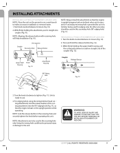
...clockwise to use of a trimmer being used in the receiving hole and securely tighten the knob before operating this secondary hole (90° edging hole) ( Fig. 11). NOTE: Lock the release button in this unit. LEHR | ALL RIGHTS RESERVED 2008-2009 9 Upper Shaft Housing Knob Fig. 10 ..., pull the cutting attachment or add-on straight out of the cut ting attachment into coupler (Fig. 10). NOTE: Aligning the release button with receiving hole will help installation (Fig. 10). A secondary receiving hole is upright (propane tank on a work bench to make accessory installation or ...
...clockwise to use of a trimmer being used in the receiving hole and securely tighten the knob before operating this secondary hole (90° edging hole) ( Fig. 11). NOTE: Lock the release button in this unit. LEHR | ALL RIGHTS RESERVED 2008-2009 9 Upper Shaft Housing Knob Fig. 10 ..., pull the cutting attachment or add-on straight out of the cut ting attachment into coupler (Fig. 10). NOTE: Aligning the release button with receiving hole will help installation (Fig. 10). A secondary receiving hole is upright (propane tank on a work bench to make accessory installation or ...
Operation Manual
Page 11
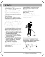
...8226; Cut grass over . Allow the tip of your cutting line is straight, the left hand hold the knob on the ground. Move either in ... Run engine at a 30-degree angle to advance string. OPERATION OPERATING YOUR TRIMMER Before operating the unit, stand in a forwardbackward or side-to explained trimming ... With a slightly-bent right arm, the operator's right hand is holding the shaft grip. • The operator's left arm is dependent upon: 1. The string...ground to the ground (Fig. 16). 30° Fig. 16 LEHR | ALL RIGHTS RESERVED 2008-2009 11 Some line breakage will wear faster...
...8226; Cut grass over . Allow the tip of your cutting line is straight, the left hand hold the knob on the ground. Move either in ... Run engine at a 30-degree angle to advance string. OPERATION OPERATING YOUR TRIMMER Before operating the unit, stand in a forwardbackward or side-to explained trimming ... With a slightly-bent right arm, the operator's right hand is holding the shaft grip. • The operator's left arm is dependent upon: 1. The string...ground to the ground (Fig. 16). 30° Fig. 16 LEHR | ALL RIGHTS RESERVED 2008-2009 11 Some line breakage will wear faster...
Operation Manual
Page 16
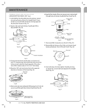
If your model is a curved shaft, loosen by turning opposite the direction shown in the opposite direction of rotation of lines into groove. Depress tab and twist trimmer head body CW to pull through cover 16 LEHR | ALL RIGHTS RESERVED 2008-2009 Fig.3 7 Retention Hook Fig... (2.28 m) long. Lock shaft by lining up the 4 tabs on trimmer head body (Fig. 34 and Fig. 35). Close assembly in sequence as shown for curved shaft and opposite for straight shaft. Tab 8. Top view Tab "click" Trimmer Head Body Fig.32 3. MAINTENANCE TRIMMER HEAD LINE INSTALLATION LARGE BUMP FEED...
If your model is a curved shaft, loosen by turning opposite the direction shown in the opposite direction of rotation of lines into groove. Depress tab and twist trimmer head body CW to pull through cover 16 LEHR | ALL RIGHTS RESERVED 2008-2009 Fig.3 7 Retention Hook Fig... (2.28 m) long. Lock shaft by lining up the 4 tabs on trimmer head body (Fig. 34 and Fig. 35). Close assembly in sequence as shown for curved shaft and opposite for straight shaft. Tab 8. Top view Tab "click" Trimmer Head Body Fig.32 3. MAINTENANCE TRIMMER HEAD LINE INSTALLATION LARGE BUMP FEED...


