Instruction Manual
Page 1
TFT LCD Widescreen Television Instruction Manual TFDVD1574/1973/2274 Please read this manual carefully before connection and use
TFT LCD Widescreen Television Instruction Manual TFDVD1574/1973/2274 Please read this manual carefully before connection and use
Instruction Manual
Page 2
... and the other end to do not perform any servicing other than that is intended to alert the user to the presence of electric to manual for a long time, disconnect the plug from the remote. Model No. The exclamation point within the product's enclosure that all the connections have been properly...
... and the other end to do not perform any servicing other than that is intended to alert the user to the presence of electric to manual for a long time, disconnect the plug from the remote. Model No. The exclamation point within the product's enclosure that all the connections have been properly...
Instruction Manual
Page 3
... to radio or television reception, which the receiver is connected. •• Consult the dealer or an experienced radio/TV technician for help Use of shielded cable is encouraged to try to correct the interference by method claims of certain U.S. ...by Macrovision Corporation and other intellectual property rights owned by Macrovision Corporation. However, there is no guarantee that is prohibited. LCD Information The LCD panel used in a particular installation. Copyright Protection Unauthorized copying, broadcasting, public performance, and lending of disks are designed ...
... to radio or television reception, which the receiver is connected. •• Consult the dealer or an experienced radio/TV technician for help Use of shielded cable is encouraged to try to correct the interference by method claims of certain U.S. ...by Macrovision Corporation and other intellectual property rights owned by Macrovision Corporation. However, there is no guarantee that is prohibited. LCD Information The LCD panel used in a particular installation. Copyright Protection Unauthorized copying, broadcasting, public performance, and lending of disks are designed ...

Instruction Manual
Page 14
The white/red plug of the AV cable can also be used separately to the manual of the AV cable is for the audio connection and the yellow plug for the video connection. Cable Connections Figure. AV Input NOTE: 111 Be sure to have all necessary connections properly done before connect the power supply. 222 When input the AV signal, refer to input the audio signal in the S-video/Component connection. Cable connections Component Input S-Video Input NOTE: We supply the AV cable and the power cord with this product. The white/red plug of the external sources as well. 8
The white/red plug of the AV cable can also be used separately to the manual of the AV cable is for the audio connection and the yellow plug for the video connection. Cable Connections Figure. AV Input NOTE: 111 Be sure to have all necessary connections properly done before connect the power supply. 222 When input the AV signal, refer to input the audio signal in the S-video/Component connection. Cable connections Component Input S-Video Input NOTE: We supply the AV cable and the power cord with this product. The white/red plug of the external sources as well. 8
Instruction Manual
Page 20
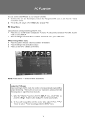
... In jack. PC Function You can be automatically regulated for menu descriptions. NOTE: Please see the TV section for a proper functioning. While working with the monitor after, adjust "H-Pos", "V-Pos", "Clock..." as well as your expectation, please perform the following steps to adjust the screen manually . 111 Enter the "Advanced" sub-menu from the SETUP menu, select "Auto" and press the ..., press OK to select VGA PC Setup Menu Various features can use the unit's TFT LCD as "Phase" accordingly under the SETUP menu. 14 See the "Cable Connection" section. ...
... In jack. PC Function You can be automatically regulated for menu descriptions. NOTE: Please see the TV section for a proper functioning. While working with the monitor after, adjust "H-Pos", "V-Pos", "Clock..." as well as your expectation, please perform the following steps to adjust the screen manually . 111 Enter the "Advanced" sub-menu from the SETUP menu, select "Auto" and press the ..., press OK to select VGA PC Setup Menu Various features can use the unit's TFT LCD as "Phase" accordingly under the SETUP menu. 14 See the "Cable Connection" section. ...
Instruction Manual
Page 27
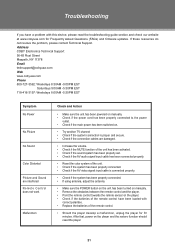
...adjust the antenna. •• Make sure the POWER button on the unit has been turned on manually. •• Remove the obstacles between the remote control and the player. •• Point...the troubleshooting guide section and check our website at www.cobyusa.com for 30 minutes. Address COBY Electronics Technical Support 56-65 Rust Street Maspeth, NY 11378 Email [email protected] Web ... •• Check if the main power has been switched on. •• Try another TV channel •• Check if the system connection is proper and secure. •• Check if...
...adjust the antenna. •• Make sure the POWER button on the unit has been turned on manually. •• Remove the obstacles between the remote control and the player. •• Point...the troubleshooting guide section and check our website at www.cobyusa.com for 30 minutes. Address COBY Electronics Technical Support 56-65 Rust Street Maspeth, NY 11378 Email [email protected] Web ... •• Check if the main power has been switched on. •• Try another TV channel •• Check if the system connection is proper and secure. •• Check if...
Instruction Manual
Page 29
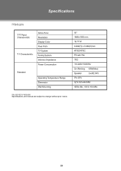
Specifications TFDVD 2274 TFT Panel Characteristic TV Characteristic Active Area Resolution Display Color Pixel Pitch TV System Tuning System Antenna Impedance Power Consumption Standard Operating Temperature Range Dimension Wall Mounting 22" 1680x1050 mm 16.77 M 0.282(H) x 0.282(V)mm ATSC/NTSC FS with PLL 75Ω 110-240V 50/60Hz On Working 65W(Max) Speaker 2x(4Ω,5W) 0ºc-40ºc 527x167x444 MM VESA M4, 100 X 100 MM P/N: 907-FD15-7400-00R Specifications and manual are subject to change without prior notice. 23
Specifications TFDVD 2274 TFT Panel Characteristic TV Characteristic Active Area Resolution Display Color Pixel Pitch TV System Tuning System Antenna Impedance Power Consumption Standard Operating Temperature Range Dimension Wall Mounting 22" 1680x1050 mm 16.77 M 0.282(H) x 0.282(V)mm ATSC/NTSC FS with PLL 75Ω 110-240V 50/60Hz On Working 65W(Max) Speaker 2x(4Ω,5W) 0ºc-40ºc 527x167x444 MM VESA M4, 100 X 100 MM P/N: 907-FD15-7400-00R Specifications and manual are subject to change without prior notice. 23


