Software Guide
Page 35
...T E R 1 The Catalyst 6000 family switches support the following configurations: • Supervisor Engine 2, Policy Feature Card 2 (PFC2), and Multilayer Switch Feature Card 2 (MSFC2) • Supervisor Engine 2 and PFC2 • Supervisor Engine 1, PFC, and MSFC or MSFC2 • Supervisor Engine 1 and PFC • Supervisor Engine 1 Note The Switch Fabric Module is supported only in the Catalyst 6000 Family Multilayer ...protocols, and MIBs supported by the Catalyst 6000 family switches. Note This publication includes the information that previously was in Catalyst 6500 series switches.
...T E R 1 The Catalyst 6000 family switches support the following configurations: • Supervisor Engine 2, Policy Feature Card 2 (PFC2), and Multilayer Switch Feature Card 2 (MSFC2) • Supervisor Engine 2 and PFC2 • Supervisor Engine 1, PFC, and MSFC or MSFC2 • Supervisor Engine 1 and PFC • Supervisor Engine 1 Note The Switch Fabric Module is supported only in the Catalyst 6000 Family Multilayer ...protocols, and MIBs supported by the Catalyst 6000 family switches. Note This publication includes the information that previously was in Catalyst 6500 series switches.

Software Guide
Page 303
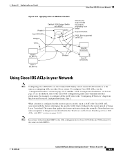
..., the ACLs are applied on routed/Layer 3-switched packets. Output Cisco IOS ACL 4. VACL for bridged packets, routed packets, and multicast packets. Figure 16-1 Applying ACLs on Bridged Packets VACL Bridged Host A (VLAN 10) Catalyst 6500 Series Switch with PFC Host B (VLAN 10) 26961 Routed Packets... Figure 16-2 shows how ACLs are applied in the following order: 1. Chapter 16 Configuring Access Control Applying Cisco IOS ACLs and VACLs on VLANs Applying Cisco IOS ACLs and VACLs on ...
..., the ACLs are applied on routed/Layer 3-switched packets. Output Cisco IOS ACL 4. VACL for bridged packets, routed packets, and multicast packets. Figure 16-1 Applying ACLs on Bridged Packets VACL Bridged Host A (VLAN 10) Catalyst 6500 Series Switch with PFC Host B (VLAN 10) 26961 Routed Packets... Figure 16-2 shows how ACLs are applied in the following order: 1. Chapter 16 Configuring Access Control Applying Cisco IOS ACLs and VACLs on VLANs Applying Cisco IOS ACLs and VACLs on ...

Software Guide
Page 304
...6000 Family Software Configuration Guide-Releases 6.3 and 6.4 78-13315-02 Packets that need multicast expansion: a. Packets after multicast expansion: a. Applying Cisco IOS ACLs and VACLs on VLANs Chapter 16 Configuring Access Control Figure 16-2 Applying ACLs on packets that need multicast expansion. VACL for input ...applied on Routed Packets Routed Input IOS ACL Bridged VACL MSFC Output IOS ACL VACL Bridged Host A (VLAN 10) Catalyst 6500 series switches with MSFC Host B (VLAN 20) 26964 Multicast Packets Figure 16-3 shows how ACLs are applied in the following order: 1....
...6000 Family Software Configuration Guide-Releases 6.3 and 6.4 78-13315-02 Packets that need multicast expansion: a. Packets after multicast expansion: a. Applying Cisco IOS ACLs and VACLs on VLANs Chapter 16 Configuring Access Control Figure 16-2 Applying ACLs on packets that need multicast expansion. VACL for input ...applied on Routed Packets Routed Input IOS ACL Bridged VACL MSFC Output IOS ACL VACL Bridged Host A (VLAN 10) Catalyst 6500 series switches with MSFC Host B (VLAN 20) 26964 Multicast Packets Figure 16-3 shows how ACLs are applied in the following order: 1....
Software Guide
Page 305
...and the "VACL Configuration Guidelines" section on page 16-28. Note that there are some exceptions to process traffic (such as NAT), the Cisco IOS ACL associated with PFC" section on page 16-10. In addition, refer to the "Configuring IP Services" chapter in the Network Protocols... ACLs in your Network Figure 16-3 Applying ACLs on Multicast Packets Routed Input IOS ACL Bridged VACL Catalyst 6500 Series Switch with redundant MSFCs, the ACL configurations for Cisco IOS ACLs and VACLs must be the same on both MSFCs. 78-13315-02 Catalyst 6000 Family Software Configuration Guide-...
...and the "VACL Configuration Guidelines" section on page 16-28. Note that there are some exceptions to process traffic (such as NAT), the Cisco IOS ACL associated with PFC" section on page 16-10. In addition, refer to the "Configuring IP Services" chapter in the Network Protocols... ACLs in your Network Figure 16-3 Applying ACLs on Multicast Packets Routed Input IOS ACL Bridged VACL Catalyst 6500 Series Switch with redundant MSFCs, the ACL configurations for Cisco IOS ACLs and VACLs must be the same on both MSFCs. 78-13315-02 Catalyst 6000 Family Software Configuration Guide-...

Software Guide
Page 319
...-02 Catalyst 6000 Family Software Configuration Guide-Releases 6.3 and 6.4 16-23 Commit the VACL. Chapter 16 Configuring Access Control Figure 16-4 Wiring Closet Configuration Catalyst 6500 series switches with MSFC Using VACLs in a VLAN. To redirect broadcast traffic to a specific server port, perform this task in privileged mode (TCP port 5000...
...-02 Catalyst 6000 Family Software Configuration Guide-Releases 6.3 and 6.4 16-23 Commit the VACL. Chapter 16 Configuring Access Control Figure 16-4 Wiring Closet Configuration Catalyst 6500 series switches with MSFC Using VACLs in a VLAN. To redirect broadcast traffic to a specific server port, perform this task in privileged mode (TCP port 5000...

Software Guide
Page 320
Permit other responses. Commit the VACL. Map the VACL to a Specific Server Port VACL Target server Host A 4/1 Catalyst 6500 series switches with PFC Host B VLAN 10 Application broadcast packet Host C 26960 Restricting the DHCP Response for a specific server, perform this task in privileged mode (...
Permit other responses. Commit the VACL. Map the VACL to a Specific Server Port VACL Target server Host A 4/1 Catalyst 6500 series switches with PFC Host B VLAN 10 Application broadcast packet Host C 26960 Restricting the DHCP Response for a specific server, perform this task in privileged mode (...

Software Guide
Page 321
...; Hosts in subnet 10.1.2.0/24 in VLAN 20 should not have access. Figure 16-6 Redirect DHCP Response for a Specific Server VACL Target server 1.2.3.4 Host A Catalyst 6500 series switches with PFC VLAN 10 DHCP response packets Host B Host C 26962 Denying Access to a Server on another VLAN, perform this task in VLAN 10...
...; Hosts in subnet 10.1.2.0/24 in VLAN 20 should not have access. Figure 16-6 Redirect DHCP Response for a Specific Server VACL Target server 1.2.3.4 Host A Catalyst 6500 series switches with PFC VLAN 10 DHCP response packets Host B Host C 26962 Denying Access to a Server on another VLAN, perform this task in VLAN 10...

Software Guide
Page 322
...VLAN VACL 10.1.1.100 Server (VLAN 10) 10.1.1.4 Host (VLAN 10) 10.1.1.8 Host (VLAN 10) Catalyst 6500 series switches with PFC2. In releases prior to software release 6.1(1), you to all the secondary VLANs. To allow...; You can map VACLs to secondary VLANs or primary VLANs. • Cisco IOS ACLs that are mapped to a primary VLAN get mapped to the associated secondary VLANs. • You... VLANs. You can be either community VLANs or isolated VLANs. ARP traffic is only available with Supervisor Engine 2 with PFC Subnet 10.1.2.0/24 Host (VLAN 20) 26963 Restricting ARP Traffic Note This feature...
...VLAN VACL 10.1.1.100 Server (VLAN 10) 10.1.1.4 Host (VLAN 10) 10.1.1.8 Host (VLAN 10) Catalyst 6500 series switches with PFC2. In releases prior to software release 6.1(1), you to all the secondary VLANs. To allow...; You can map VACLs to secondary VLANs or primary VLANs. • Cisco IOS ACLs that are mapped to a primary VLAN get mapped to the associated secondary VLANs. • You... VLANs. You can be either community VLANs or isolated VLANs. ARP traffic is only available with Supervisor Engine 2 with PFC Subnet 10.1.2.0/24 Host (VLAN 20) 26963 Restricting ARP Traffic Note This feature...

Software Guide
Page 344
... the example configuration shown in the Edit Buffer, page 16-53 • Configuring Hosts for PBF, page 16-53 Figure 16-8 Policy-Based Forwarding Catalyst 6500 series switches PFC2 MAC address: 00-11-11-11-11-11 VLAN 10 Host A IP 10.0.0.1 MAC 00:00:00:00:00:0A Interface: Ethernet1...
... the example configuration shown in the Edit Buffer, page 16-53 • Configuring Hosts for PBF, page 16-53 Figure 16-8 Policy-Based Forwarding Catalyst 6500 series switches PFC2 MAC address: 00-11-11-11-11-11 VLAN 10 Host A IP 10.0.0.1 MAC 00:00:00:00:00:0A Interface: Ethernet1...

Software Guide
Page 352
Configuring Policy-Based Forwarding Chapter 16 Configuring Access Control Figure 16-9 Policy-Based Forwarding Configuration Example Catalyst 6500 series switches PFC2 MAC address: 00-11-22-33-44-55 6/17 6/9 VLAN 1 VLAN 1 Hosts IP: 44.0.0.1 - 44.0.0.17 MAC:00-20-20-20-20-...
Configuring Policy-Based Forwarding Chapter 16 Configuring Access Control Figure 16-9 Policy-Based Forwarding Configuration Example Catalyst 6500 series switches PFC2 MAC address: 00-11-22-33-44-55 6/17 6/9 VLAN 1 VLAN 1 Hosts IP: 44.0.0.1 - 44.0.0.17 MAC:00-20-20-20-20-...

Software Guide
Page 375
Chapter 18 Configuring Dynamic Port VLAN Membership with VMPS Dynamic Port VLAN Membership with VMPS Configuration Examples Figure 18-1 Dynamic Port VLAN Membership Configuration Catalyst 6500 series switches Primary VMPS Server 1 Switch 1 172.20.26.150 3/1 Client End station 1 Switch 2 172.20.26.151 Catalyst 6000 ...20.22.7 Switch 7 172.20.26.156 Switch 8 172.20.26.157 Client Switch 9 End station 2 172.20.26.158 Catalyst 6500 series switches Secondary VMPS Server 3 Switch 10 172.20.26.159 55908 78-13315-02 Catalyst 6000 Family Software Configuration Guide-Releases 6.3 and ...
Chapter 18 Configuring Dynamic Port VLAN Membership with VMPS Dynamic Port VLAN Membership with VMPS Configuration Examples Figure 18-1 Dynamic Port VLAN Membership Configuration Catalyst 6500 series switches Primary VMPS Server 1 Switch 1 172.20.26.150 3/1 Client End station 1 Switch 2 172.20.26.151 Catalyst 6000 ...20.22.7 Switch 7 172.20.26.156 Switch 8 172.20.26.157 Client Switch 9 End station 2 172.20.26.158 Catalyst 6500 series switches Secondary VMPS Server 3 Switch 10 172.20.26.159 55908 78-13315-02 Catalyst 6000 Family Software Configuration Guide-Releases 6.3 and ...

Software Guide
Page 416
... sends the resulting packet to the KDC on the Kerberos server. 2. Figure 21-1 Kerberized Telnet Connection Host (Telnet client) Kerberos server 1 (contains KDC) 2 3 4 5 6 6000 Catalyst 6500 series switches 30794 21-6 Catalyst 6000 Family Software Configuration Guide-Releases 6.3 and 6.4 78-13315-02 Understanding How Authentication Works Chapter 21 Configuring Switch Access Using...
... sends the resulting packet to the KDC on the Kerberos server. 2. Figure 21-1 Kerberized Telnet Connection Host (Telnet client) Kerberos server 1 (contains KDC) 2 3 4 5 6 6000 Catalyst 6500 series switches 30794 21-6 Catalyst 6000 Family Software Configuration Guide-Releases 6.3 and 6.4 78-13315-02 Understanding How Authentication Works Chapter 21 Configuring Switch Access Using...

Software Guide
Page 707
... to support Common Open Policy Service (COPS) and Resouce ReSerVation Protocol (RSVP). Implementing QoS in a timely manner. The QoS feature on the Catalyst 6500 series. • Supervisor Engine 1 and Supervisor Engine 2 provide policing only for the commands used in this publication and all traffic has an equal chance of these sections: • Understanding How QoS...
... to support Common Open Policy Service (COPS) and Resouce ReSerVation Protocol (RSVP). Implementing QoS in a timely manner. The QoS feature on the Catalyst 6500 series. • Supervisor Engine 1 and Supervisor Engine 2 provide policing only for the commands used in this publication and all traffic has an equal chance of these sections: • Understanding How QoS...

Software Guide
Page 783
... the Layer 2 table that the router MAC address is configured). Chapter 42 Configuring ASLB Understanding How ASLB Works Figure 42-1 ASLB Functional Description Clients Catalyst 6500 series switches PK PR PL PA PB PM Server pool S1 S2 S3 28062 VLAN 10 VLAN 20 LocalDirector Layer 3 Operations for ASLB You can...
... the Layer 2 table that the router MAC address is configured). Chapter 42 Configuring ASLB Understanding How ASLB Works Figure 42-1 ASLB Functional Description Clients Catalyst 6500 series switches PK PR PL PA PB PM Server pool S1 S2 S3 28062 VLAN 10 VLAN 20 LocalDirector Layer 3 Operations for ASLB You can...

Software Guide
Page 785
... of 14 in Layer 3 table - Enabler frame - Chapter 42 Configuring ASLB Understanding How ASLB Works Figure 42-2 Client to Server ASLB Packet Flow Clients Catalyst 6500 series switches Path 3 PK PR PL PA PB PM Path 1 Path 2 Server pool S1 S2 S3 VLAN 10 VLAN 20 LocalDirector 28063 Table 42-2 Client...
... of 14 in Layer 3 table - Enabler frame - Chapter 42 Configuring ASLB Understanding How ASLB Works Figure 42-2 Client to Server ASLB Packet Flow Clients Catalyst 6500 series switches Path 3 PK PR PL PA PB PM Path 1 Path 2 Server pool S1 S2 S3 VLAN 10 VLAN 20 LocalDirector 28063 Table 42-2 Client...

Software Guide
Page 786
..." section on page 42-4 with the exception that the LocalDirector selected. 3. Figure 42-3 Server to Client ASLB Packet Flow Clients VLAN 10 VLAN 20 Catalyst 6500 series switches Path 3 PK Server pool S1 S2 S3 PR PL PA PB PM Path 2 Path 1 LocalDirector 28064 Table 42-4 Server to -server direction, the...
..." section on page 42-4 with the exception that the LocalDirector selected. 3. Figure 42-3 Server to Client ASLB Packet Flow Clients VLAN 10 VLAN 20 Catalyst 6500 series switches Path 3 PK Server pool S1 S2 S3 PR PL PA PB PM Path 2 Path 1 LocalDirector 28064 Table 42-4 Server to -server direction, the...

Software Guide
Page 799
Figure 42-4 shows the example network; Figure 42-4 ASLB Configuration Example Server pool Clients VLAN 7 VLAN 5 S1 Catalyst 6500 series switches 5/n 5/6 5/n S2 5/7 5/5 5/n S3 LocalDirector S 28229 78-13315-02 The router configuration is as follows (MSM is used in a "leastconns" fashion (which is 00-e0-...
Figure 42-4 shows the example network; Figure 42-4 ASLB Configuration Example Server pool Clients VLAN 7 VLAN 5 S1 Catalyst 6500 series switches 5/n 5/6 5/n S2 5/7 5/5 5/n S3 LocalDirector S 28229 78-13315-02 The router configuration is as follows (MSM is used in a "leastconns" fashion (which is 00-e0-...

Software Guide
Page 802
... ASLB Figure 42-5 ASLB Redundant Configuration Example LocalDirector 1 Clients VLAN 9 VLAN 5 Router 1 3/7 f1 f2 3/41 VLAN 9 3/23 3/8 Catalyst 6500 series switches 1 VLAN 5 VLAN 5 & 9 (ISL trunk) Router 2 3/23 f1 f2 3/42 VLAN 9 3/27 Catalyst 6500 series switches 2 3/28 VLAN 5 VLAN 9 VLAN 5 LocalDirector LocalDirector 2 failover cable IP Addresses The IP addresses are as follows...
... ASLB Figure 42-5 ASLB Redundant Configuration Example LocalDirector 1 Clients VLAN 9 VLAN 5 Router 1 3/7 f1 f2 3/41 VLAN 9 3/23 3/8 Catalyst 6500 series switches 1 VLAN 5 VLAN 5 & 9 (ISL trunk) Router 2 3/23 f1 f2 3/42 VLAN 9 3/27 Catalyst 6500 series switches 2 3/28 VLAN 5 VLAN 9 VLAN 5 LocalDirector LocalDirector 2 failover cable IP Addresses The IP addresses are as follows...

Software Guide
Page 807
...modules. If you specify none, the switch ports are handled if the Switch Fabric Module is supported in the 13-slot Catalyst 6500 switches. Install the WS-C6500-SFM in either slot 5 or 6 in this chapter, refer to specify how packets are disabled and switching stops. Install ...the WS-X6500-SFM 2 in slots 7 or 8 in the Catalyst 6500 6-slot, 9-slot, 13-slot, and 6509-NEB chassis. The WS-X6500-SFM 2 is removed or fails. The Switch Fabric Module also provides fabric-enabled modules with Supervisor Engine 2 in flow-through mode. A two-...
...modules. If you specify none, the switch ports are handled if the Switch Fabric Module is supported in the 13-slot Catalyst 6500 switches. Install the WS-C6500-SFM in either slot 5 or 6 in this chapter, refer to specify how packets are disabled and switching stops. Install ...the WS-X6500-SFM 2 in slots 7 or 8 in the Catalyst 6500 6-slot, 9-slot, 13-slot, and 6509-NEB chassis. The WS-X6500-SFM 2 is removed or fails. The Switch Fabric Module also provides fabric-enabled modules with Supervisor Engine 2 in flow-through mode. A two-...

Software Guide
Page 808
...-1 Switching Modes with fabric-enabled and nonfabric-enabled modules installed. This mode is forwarded between the local bus and the supervisor engine bus. From the supervisor engine, you install a Switch Fabric Module in a Catalyst 6500 series switch, the traffic is forwarded to or from modules in one of the frame) is sent over the switch...
...-1 Switching Modes with fabric-enabled and nonfabric-enabled modules installed. This mode is forwarded between the local bus and the supervisor engine bus. From the supervisor engine, you install a Switch Fabric Module in a Catalyst 6500 series switch, the traffic is forwarded to or from modules in one of the frame) is sent over the switch...