
Hardware Maintenance Manual
Page 10
...-Port Ethernet Network Processor Module LEDs 4-4 Token Ring Module Network Connector 4-5 Four-Port Serial Network Processor Module Ports 4-6 G.703/G.704 Serial Network Processor Module Ports (DB-15) 4-6 Serial Port Labeled V2 4-7 Dual Serial Network Processor Module-Top View 4-8 Dual Serial Port LED Card-Side View 4-8 Dual-Attachment Single-Mode FDDI Module-End View 4-9 x Cisco 4000 Series Hardware Installation...
...-Port Ethernet Network Processor Module LEDs 4-4 Token Ring Module Network Connector 4-5 Four-Port Serial Network Processor Module Ports 4-6 G.703/G.704 Serial Network Processor Module Ports (DB-15) 4-6 Serial Port Labeled V2 4-7 Dual Serial Network Processor Module-Top View 4-8 Dual Serial Port LED Card-Side View 4-8 Dual-Attachment Single-Mode FDDI Module-End View 4-9 x Cisco 4000 Series Hardware Installation...
Hardware Maintenance Manual
Page 61
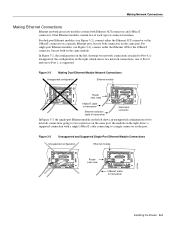
...network connections, one to Port 0 and one to Port 0, is supported. Figure 3-2 Making Dual-Ethernet Module Network Connections Unsupported configuration Ethernet module AUI AUI AUI Router AUI (rear view) H1571a AUX 10BaseT cable AUX to transceiver Slide-latch Ethernet transition ...connector cable to transceiver In Figure 3-3, the single-port Ethernet module on the left shows an unsupported configuration of connector interface. the module on the right shows a supported connection with a single 10BaseT cable connecting to transceiver ...
...network connections, one to Port 0 and one to Port 0, is supported. Figure 3-2 Making Dual-Ethernet Module Network Connections Unsupported configuration Ethernet module AUI AUI AUI Router AUI (rear view) H1571a AUX 10BaseT cable AUX to transceiver Slide-latch Ethernet transition ...connector cable to transceiver In Figure 3-3, the single-port Ethernet module on the left shows an unsupported configuration of connector interface. the module on the right shows a supported connection with a single 10BaseT cable connecting to transceiver ...
