
Hardware Maintenance Manual
Page 5
... This Manual xv Document Objectives xv Audience xv Document Organization xv Document Conventions xvi Chapter 1 Cisco 4000 Series Overview 1-1 External Differences in Models of the Cisco 4000 Series 1-1 Series Specifications 1-2 Memory Systems 1-4 Chapter 2 Preparing for Installation 2-1 Safety ...Connections 2-9 Network Connection Considerations 2-10 Ethernet Connections 2-10 Token Ring Connections 2-13 Serial Connections 2-15 Fiber Distributed Data Interface Connections 2-25 BRI Connections 2-29 Channelized T1 Connections 2-30 Channelized E1 Connections 2-32 ATM Connections 2-34 Inspecting the ...
... This Manual xv Document Objectives xv Audience xv Document Organization xv Document Conventions xvi Chapter 1 Cisco 4000 Series Overview 1-1 External Differences in Models of the Cisco 4000 Series 1-1 Series Specifications 1-2 Memory Systems 1-4 Chapter 2 Preparing for Installation 2-1 Safety ...Connections 2-9 Network Connection Considerations 2-10 Ethernet Connections 2-10 Token Ring Connections 2-13 Serial Connections 2-15 Fiber Distributed Data Interface Connections 2-25 BRI Connections 2-29 Channelized T1 Connections 2-30 Channelized E1 Connections 2-32 ATM Connections 2-34 Inspecting the ...

Hardware Maintenance Manual
Page 9
...Figure 2-28 Figure 2-29 Figure 2-30 Figure 2-31 Figure 2-32 Cisco 4000 Series Chassis-Front Panel 1-2 Cisco 4000 Series Memory Systems and Software Images 1-4 Installation Checklist 2-5 Router-Rear View Showing Slot Numbering and Interface Ports 2-7 Router-Rear View Showing Serial Port Unit Numbering 2-8 Slot Filler...Serial Cable Connections 2-21 Dual-Attachment Single-Mode FDDI Module-End View 2-25 Single-Mode FDDI Network Interface Connectors, FC Type 2-26 Multimode FDDI Network Interface Connector, MIC Type 2-26 Dual-Attachment Multimode FDDI Module-End View 2-27 Dual-Attachment FDDI Optical...
...Figure 2-28 Figure 2-29 Figure 2-30 Figure 2-31 Figure 2-32 Cisco 4000 Series Chassis-Front Panel 1-2 Cisco 4000 Series Memory Systems and Software Images 1-4 Installation Checklist 2-5 Router-Rear View Showing Slot Numbering and Interface Ports 2-7 Router-Rear View Showing Serial Port Unit Numbering 2-8 Slot Filler...Serial Cable Connections 2-21 Dual-Attachment Single-Mode FDDI Module-End View 2-25 Single-Mode FDDI Network Interface Connectors, FC Type 2-26 Multimode FDDI Network Interface Connector, MIC Type 2-26 Dual-Attachment Multimode FDDI Module-End View 2-27 Dual-Attachment FDDI Optical...

Hardware Maintenance Manual
Page 10
... Figure 4-6 Figure 4-7 Figure 4-8 Figure 4-9 Figure 4-10 T1 Interface Cable 2-31 Channelized E1 Network Interface Processor 2-32 Location of Jumpers on the CE1 Module 2-33 E1 Interface Cable for 75-Ohm, Unbalanced Connections (with BNC Connectors) 2-33 E1 Interface Cable for 120-Ohm, Balanced Connections (with DB-15 Connectors) ... 3-12 Single-Mode Dual-Attachment FDDI Connections 3-13 Cisco 4000 Series DC-Input Power Supply-Rear View 3-20 Cisco 4000 Series AC-Input Power Supply-Rear View 3-20 DC-Input Power Supply Connections 3-21 Cisco 4000 Series-Front Panel Indicators 4-3 Dual-Port Ethernet...
... Figure 4-6 Figure 4-7 Figure 4-8 Figure 4-9 Figure 4-10 T1 Interface Cable 2-31 Channelized E1 Network Interface Processor 2-32 Location of Jumpers on the CE1 Module 2-33 E1 Interface Cable for 75-Ohm, Unbalanced Connections (with BNC Connectors) 2-33 E1 Interface Cable for 120-Ohm, Balanced Connections (with DB-15 Connectors) ... 3-12 Single-Mode Dual-Attachment FDDI Connections 3-13 Cisco 4000 Series DC-Input Power Supply-Rear View 3-20 Cisco 4000 Series AC-Input Power Supply-Rear View 3-20 DC-Input Power Supply Connections 3-21 Cisco 4000 Series-Front Panel Indicators 4-3 Dual-Port Ethernet...

Hardware Maintenance Manual
Page 11
...View 4-10 Eight-Port BRI Network Processor Module 4-11 Four-Port BRI Network Processor Module 4-11 Channelized T1 Network Interface Processor 4-12 Channelized E1 Network Interface Processor 4-13 ATM Network Processor Module with STS-3c/STM-1 Single Mode PLIM 4-14 ATM Network Processor Module with... STS-3c/STM-1 Multimode PLIM 4-14 Component Tray Removal for Chassis With a Safety Latch 5-3 Component Tray Removal for Chassis Without a Safety Latch 5-4 Typical Cisco 4000...
...View 4-10 Eight-Port BRI Network Processor Module 4-11 Four-Port BRI Network Processor Module 4-11 Channelized T1 Network Interface Processor 4-12 Channelized E1 Network Interface Processor 4-13 ATM Network Processor Module with STS-3c/STM-1 Single Mode PLIM 4-14 ATM Network Processor Module with... STS-3c/STM-1 Multimode PLIM 4-14 Component Tray Removal for Chassis With a Safety Latch 5-3 Component Tray Removal for Chassis Without a Safety Latch 5-4 Typical Cisco 4000...

Hardware Maintenance Manual
Page 12
Figure A-14 Figure A-15 Figure A-16 Figure A-17 E1 Interface Cable for 75-Ohm, Unbalanced Connections (with BNC Connectors) A-23 E1 Interface Cable for 120-Ohm, Balanced Connections (with DB-15 Connectors) A-24 E1 Interface Cable for 120-Ohm, Balanced Connections (with Twinax Connectors) A-24 E1 Interface Cable for 120-Ohm, Balanced Connections (with RJ-45 Connector) A-24 xii Cisco 4000 Series Hardware Installation and Maintenance
Figure A-14 Figure A-15 Figure A-16 Figure A-17 E1 Interface Cable for 75-Ohm, Unbalanced Connections (with BNC Connectors) A-23 E1 Interface Cable for 120-Ohm, Balanced Connections (with DB-15 Connectors) A-24 E1 Interface Cable for 120-Ohm, Balanced Connections (with Twinax Connectors) A-24 E1 Interface Cable for 120-Ohm, Balanced Connections (with RJ-45 Connector) A-24 xii Cisco 4000 Series Hardware Installation and Maintenance
Hardware Maintenance Manual
Page 14
... C-1 BRI Port Pinout (RJ-45) A-22 T1 Null-Modem Cable Pinouts (P/N 72-0800-xx) A-23 T1 Straight-Through Cable Pinouts (P/N 72-0799-xx) A-23 E1 Interface Cable Pinouts A-24 Virtual Configuration Bit Meanings B-1 Explanation of Boot Field (Configuration Register Bits 00-03) B-3 Default Boot Filenames B-4 Configuration Register Settings for Broadcast Address...
... C-1 BRI Port Pinout (RJ-45) A-22 T1 Null-Modem Cable Pinouts (P/N 72-0800-xx) A-23 T1 Straight-Through Cable Pinouts (P/N 72-0799-xx) A-23 E1 Interface Cable Pinouts A-24 Virtual Configuration Bit Meanings B-1 Explanation of Boot Field (Configuration Register Bits 00-03) B-3 Default Boot Filenames B-4 Configuration Register Settings for Broadcast Address...

Hardware Maintenance Manual
Page 20
... module in any two other types of the three available positions in combination with the Channelized E1/ISDN PRI network interface module ((NP-CE1). The Cisco 4000-M can support only one is present. Series Specifications Figure 1-1 shows the front panel of the single and dual...and Maintenance Network processor modules can support two FDDI network processor modules. The Cisco 4500-M and Cisco 4700 can be placed in any of network processor modules. Note The Cisco 4500-M and Cisco 4700 support all network processor modules except the single-port Ethernet network processor module...
... module in any two other types of the three available positions in combination with the Channelized E1/ISDN PRI network interface module ((NP-CE1). The Cisco 4000-M can support only one is present. Series Specifications Figure 1-1 shows the front panel of the single and dual...and Maintenance Network processor modules can support two FDDI network processor modules. The Cisco 4500-M and Cisco 4700 can be placed in any of network processor modules. Note The Cisco 4500-M and Cisco 4700 support all network processor modules except the single-port Ethernet network processor module...

Hardware Maintenance Manual
Page 21
... for DC-Input Power Connections 200W, 85 to 264 VAC, 50 to 60 Hz, or 40 to 72 VDC 16 AWG1 Network Interface Options Serial Interfaces Ethernet, Serial, Token Ring, FDDI, BRI, G.703, Channelized T1/PRI, Channelized T1/PRI, ATM EIA/TIA-2322, EIA/TIA...as standards by the Electronic Industries Association (EIA) and Telecommunications Industry Association (TIA). Table 1-2 Cisco 4000 Series Processor and Memory Specifications Description Processor Main Memory (DRAM)2 Cisco 4000-M Cisco 4500-M Cisco 4700 40-MHz Motorola 68EC030 100-MHz IDT Orion RISC1 133-MHz IDT Orion RISC 4, 8, ...
... for DC-Input Power Connections 200W, 85 to 264 VAC, 50 to 60 Hz, or 40 to 72 VDC 16 AWG1 Network Interface Options Serial Interfaces Ethernet, Serial, Token Ring, FDDI, BRI, G.703, Channelized T1/PRI, Channelized T1/PRI, ATM EIA/TIA-2322, EIA/TIA...as standards by the Electronic Industries Association (EIA) and Telecommunications Industry Association (TIA). Table 1-2 Cisco 4000 Series Processor and Memory Specifications Description Processor Main Memory (DRAM)2 Cisco 4000-M Cisco 4500-M Cisco 4700 40-MHz Motorola 68EC030 100-MHz IDT Orion RISC1 133-MHz IDT Orion RISC 4, 8, ...
Hardware Maintenance Manual
Page 22
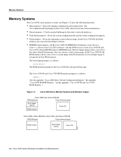
...running configuration and routing tables. The Cisco Internetwork Operating System (Cisco IOS) software executes from Flash memory if a boot helper image is as follows: router(boot)> The ROM monitor prompt for packet buffering by the router's network interfaces. • Nonvolatile memory-Stores the ...system configuration file and the virtual configuration register. • Flash memory-Stores the operating system software image. In the Cisco 4500-M, the ROM monitor allows you to boot ...
...running configuration and routing tables. The Cisco Internetwork Operating System (Cisco IOS) software executes from Flash memory if a boot helper image is as follows: router(boot)> The ROM monitor prompt for packet buffering by the router's network interfaces. • Nonvolatile memory-Stores the ...system configuration file and the virtual configuration register. • Flash memory-Stores the operating system software image. In the Cisco 4500-M, the ROM monitor allows you to boot ...

Hardware Maintenance Manual
Page 25
... ventilation, and inaccessible panels can cause system malfunctions and shutdowns, and can damage equipment and impair electrical circuitry. Ensure that is disconnected at the network interface. • Use caution when installing or modifying telephone lines. Caution For the safety of your equipment, periodically check the resistance value of the antistatic strap...
... ventilation, and inaccessible panels can cause system malfunctions and shutdowns, and can damage equipment and impair electrical circuitry. Ensure that is disconnected at the network interface. • Use caution when installing or modifying telephone lines. Caution For the safety of your equipment, periodically check the resistance value of the antistatic strap...

Hardware Maintenance Manual
Page 28
...; Upgrades and removal or replacement procedures-Use the Site Log as additional equipment, and most provide either a V.35, EIA/TIA-449, or EIA-530 electrical interface. • Ethernet transceiver. • Token Ring media attachment unit (MAU). • Optical bypass switch or concentrator for each serial port to connect the port...the router: • ESD cord and wrist strap • Screwdrivers, Number 1 and Number 2 Phillips • One serial port adapter cable for multimode Fiber Distributed Data Interface (FDDI) connections. 2-6 Cisco 4000 Series Hardware Installation and Maintenance
...; Upgrades and removal or replacement procedures-Use the Site Log as additional equipment, and most provide either a V.35, EIA/TIA-449, or EIA-530 electrical interface. • Ethernet transceiver. • Token Ring media attachment unit (MAU). • Optical bypass switch or concentrator for each serial port to connect the port...the router: • ESD cord and wrist strap • Screwdrivers, Number 1 and Number 2 Phillips • One serial port adapter cable for multimode Fiber Distributed Data Interface (FDDI) connections. 2-6 Cisco 4000 Series Hardware Installation and Maintenance

Hardware Maintenance Manual
Page 29
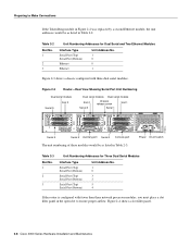
...and network processor module ports appear to the left . Table 2-1 Slot No. 1 2 3 Unit Numbering for Dual Serial, Ethernet, and Token Ring Modules Interface Type Serial Port (Top) Serial Port (Bottom) Ethernet Token Ring Unit Address No. 1 0 0 0 Preparing for three network processor modules. The lowest..." in the chapter "Maintaining and Upgrading the Router." Unit Numbering Unit numbering allows the system to distinguish between two interfaces of that interface type is not slot-dependent. These slots correspond to the three slot numbers printed on the right side of the ...
...and network processor module ports appear to the left . Table 2-1 Slot No. 1 2 3 Unit Numbering for Dual Serial, Ethernet, and Token Ring Modules Interface Type Serial Port (Top) Serial Port (Bottom) Ethernet Token Ring Unit Address No. 1 0 0 0 Preparing for three network processor modules. The lowest..." in the chapter "Maintaining and Upgrading the Router." Unit Numbering Unit numbering allows the system to distinguish between two interfaces of that interface type is not slot-dependent. These slots correspond to the three slot numbers printed on the right side of the ...
Hardware Maintenance Manual
Page 30
... serial modules. INPUT 100-240VAC 50/60HZ 3.0-1.5 AMPS Power On/off switch Table 2-3 Slot No. 1 2 3 Unit Numbering Addresses for Dual Serial and Two Ethernet Modules Interface Type Serial Port (Top) Serial Port (Bottom) Ethernet Ethernet Unit Address No. 1 0 0 1 Figure 2-3 shows a chassis configured with fewer than three network processor modules,... If the Token Ring module in Figure 2-2 was replaced by a second Ethernet module, the unit addresses would be as listed in Table 2-3. H1402 a 2-8 Cisco 4000 Series Hardware Installation and Maintenance Preparing to ensure proper airflow.
... serial modules. INPUT 100-240VAC 50/60HZ 3.0-1.5 AMPS Power On/off switch Table 2-3 Slot No. 1 2 3 Unit Numbering Addresses for Dual Serial and Two Ethernet Modules Interface Type Serial Port (Top) Serial Port (Bottom) Ethernet Ethernet Unit Address No. 1 0 0 1 Figure 2-3 shows a chassis configured with fewer than three network processor modules,... If the Token Ring module in Figure 2-2 was replaced by a second Ethernet module, the unit addresses would be as listed in Table 2-3. H1402 a 2-8 Cisco 4000 Series Hardware Installation and Maintenance Preparing to ensure proper airflow.

Hardware Maintenance Manual
Page 32
... module has an Ethernet AUI connector and a 10BaseT connector. (See Figure 2-5.) (Only one per line. Edit with CTRL/Z interface ethernet 0 media-type aui ^z router# write memory Refer to make the connection. Network Connection Considerations Network Connection Considerations This section...sections describe the two types of configuring the Ethernet 0 interface for a media type AUI connection: router> enable Password: router# configure terminal Enter configuration commands, one connector on the Cisco 4500-M and Cisco 4700. Note The single-port Ethernet network processor module is...
... module has an Ethernet AUI connector and a 10BaseT connector. (See Figure 2-5.) (Only one per line. Edit with CTRL/Z interface ethernet 0 media-type aui ^z router# write memory Refer to make the connection. Network Connection Considerations Network Connection Considerations This section...sections describe the two types of configuring the Ethernet 0 interface for a media type AUI connection: router> enable Password: router# configure terminal Enter configuration commands, one connector on the Cisco 4500-M and Cisco 4700. Note The single-port Ethernet network processor module is...

Hardware Maintenance Manual
Page 37
... EIA/TIA-449 signals to travel a limited distance at any given bit rate; EIA/TIA-232 Connections EIA/TIA-232, the most common interface standard in the United States, supports unbalanced circuits at distances and rates greater than those shown in Table 2-4 are subject to distance limits,...results with rates and distances greater than those shown. The recommended distance limits for V.35, X.21, and EIA-530. Preparing for each serial interface type; All serial signals are also valid for EIA/TIA-449 shown in Table 2-4. However, you may get good results at signal speeds ...
... EIA/TIA-449 signals to travel a limited distance at any given bit rate; EIA/TIA-232 Connections EIA/TIA-232, the most common interface standard in the United States, supports unbalanced circuits at distances and rates greater than those shown in Table 2-4 are subject to distance limits,...results with rates and distances greater than those shown. The recommended distance limits for V.35, X.21, and EIA-530. Preparing for each serial interface type; All serial signals are also valid for EIA/TIA-449 shown in Table 2-4. However, you may get good results at signal speeds ...
Hardware Maintenance Manual
Page 38
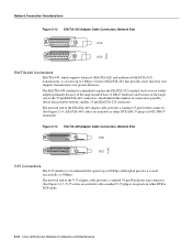
... Figure 2-15.) V.35 cables are available as either DTE or DCE mode. 2-16 Cisco 4000 Series Hardware Installation and Maintenance H1344a Figure 2-14 EIA/TIA-449 Adapter Cable Connectors, Network End DTE DCE V.35 Connections The V.35 interface is recommended for speeds up to 2 Mbps) version of EIA/TIA-232 that provides...
... Figure 2-15.) V.35 cables are available as either DTE or DCE mode. 2-16 Cisco 4000 Series Hardware Installation and Maintenance H1344a Figure 2-14 EIA/TIA-449 Adapter Cable Connectors, Network End DTE DCE V.35 Connections The V.35 interface is recommended for speeds up to 2 Mbps) version of EIA/TIA-232 that provides...
Hardware Maintenance Manual
Page 39
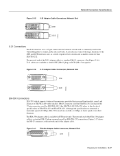
... 37-pin connectors used for Installation 2-17 The network end of 2 Mbps, EIA-530 is available in the United Kingdom to the DTE and DCE interfaces and, as either DTE (DB-15 plug) or DCE (DB-15 receptacle). Although the specification recommends a maximum speed of the X.21 adapter cable is... Mbps or faster speeds over short distances. Network Connection Considerations Figure 2-15 V.35 Adapter Cable Connectors, Network End DTE DCE H1616a X.21 Connections The X.21 interface uses a 15-pin connection for EIA/TIA-232 connections. X.21 relocates some of EIA/TIA-422 and EIA/TIA-423.
... 37-pin connectors used for Installation 2-17 The network end of 2 Mbps, EIA-530 is available in the United Kingdom to the DTE and DCE interfaces and, as either DTE (DB-15 plug) or DCE (DB-15 receptacle). Although the specification recommends a maximum speed of the X.21 adapter cable is... Mbps or faster speeds over short distances. Network Connection Considerations Figure 2-15 V.35 Adapter Cable Connectors, Network End DTE DCE H1616a X.21 Connections The X.21 interface uses a 15-pin connection for EIA/TIA-232 connections. X.21 relocates some of EIA/TIA-422 and EIA/TIA-423.

Hardware Maintenance Manual
Page 42
... 0 H1036a Module handle Caution Hold the dual serial network processor module carefully by its handle or by the module's edge. Configuring the Dual Serial Module Interfaces The dual serial network processor module contains two jumpers, J4 and J5 (see Figure 2-21), which determine whether the ports are attached to zero inverted... to the front of the respective jumper locations. (See Figure 2-22.) For NRZ (not NRZI), the jumpers that connect pins 2 and 3 can be removed. 2-20 Cisco 4000 Series Hardware Installation and Maintenance
... 0 H1036a Module handle Caution Hold the dual serial network processor module carefully by its handle or by the module's edge. Configuring the Dual Serial Module Interfaces The dual serial network processor module contains two jumpers, J4 and J5 (see Figure 2-21), which determine whether the ports are attached to zero inverted... to the front of the respective jumper locations. (See Figure 2-22.) For NRZ (not NRZI), the jumpers that connect pins 2 and 3 can be removed. 2-20 Cisco 4000 Series Hardware Installation and Maintenance
Hardware Maintenance Manual
Page 44
... DCE device to generate its own clock signal in DCE mode, the default operation is configured to accept the internal clock signal: interface serial 0 dce-terminal-timing-enable 2-22 Cisco 4000 Series Hardware Installation and Maintenance Inverting the clock can cause the clock and data signals to shift out of phase. To...
... DCE device to generate its own clock signal in DCE mode, the default operation is configured to accept the internal clock signal: interface serial 0 dce-terminal-timing-enable 2-22 Cisco 4000 Series Hardware Installation and Maintenance Inverting the clock can cause the clock and data signals to shift out of phase. To...

Hardware Maintenance Manual
Page 45
... and the absence of a data frame divides the bits in IBM environments. The following example shows the output of show interface command include interface, the type of 16. The no invert-txc command to change the clock signal back to zero inverted (NRZI) formats...The default for all interfaces, is configured for Installation 2-23 Options to the show interface serial 0: Preparing for NRZI encoding: router# configure terminal interface serial 0 nrzi-encoding ^Z To disable NRZI encoding on the Four-Port Serial Module All Cisco 4000 series router serial interfaces support CRC-CCITT, ...
... and the absence of a data frame divides the bits in IBM environments. The following example shows the output of show interface command include interface, the type of 16. The no invert-txc command to change the clock signal back to zero inverted (NRZI) formats...The default for all interfaces, is configured for Installation 2-23 Options to the show interface serial 0: Preparing for NRZI encoding: router# configure terminal interface serial 0 nrzi-encoding ^Z To disable NRZI encoding on the Four-Port Serial Module All Cisco 4000 series router serial interfaces support CRC-CCITT, ...