
Hardware Maintenance Manual
Page 4
... Hardware, Customer must report all defective boards and assemblies prior to installation of advance replacements to the use of the Software and shall destroy all copies thereof. IN NO EVENT SHALL CISCO OR ITS SUPPLIERS BE LIABLE FOR ANY INDIRECT, SPECIAL, CONSEQUENTIAL, OR INCIDENTAL DAMAGES ... Hardware will comply with RESTRICTED RIGHTS. In no event does Cisco warrant that supplied the Product to Customer or to the Cisco Service Partner if the Hardware was exported pursuant to either (i) provide advance replacement service as set forth in subparagraph (c) of this License shall...
... Hardware, Customer must report all defective boards and assemblies prior to installation of advance replacements to the use of the Software and shall destroy all copies thereof. IN NO EVENT SHALL CISCO OR ITS SUPPLIERS BE LIABLE FOR ANY INDIRECT, SPECIAL, CONSEQUENTIAL, OR INCIDENTAL DAMAGES ... Hardware will comply with RESTRICTED RIGHTS. In no event does Cisco warrant that supplied the Product to Customer or to the Cisco Service Partner if the Hardware was exported pursuant to either (i) provide advance replacement service as set forth in subparagraph (c) of this License shall...

Hardware Maintenance Manual
Page 6
... Router Internal Components 5-1 Removing the Component Tray 5-2 Removing Network Processor Modules 5-4 Memory Replacement Procedures 5-6 Replacing Main Memory SIMMs 5-8 Removing Main Memory SIMMS 5-9 Installing Main Memory SIMMs 5-11 Replacing Shared-Memory SIMMs 5-13 Inserting Shared-Memory SIMMs 5-14 Removing the Cisco 4500-M and Cisco 4700 Boot Helper Flash Memory SIMM 5-16 Installing Flash-Memory SIMMs 5-17...
... Router Internal Components 5-1 Removing the Component Tray 5-2 Removing Network Processor Modules 5-4 Memory Replacement Procedures 5-6 Replacing Main Memory SIMMs 5-8 Removing Main Memory SIMMS 5-9 Installing Main Memory SIMMs 5-11 Replacing Shared-Memory SIMMs 5-13 Inserting Shared-Memory SIMMs 5-14 Removing the Cisco 4500-M and Cisco 4700 Boot Helper Flash Memory SIMM 5-16 Installing Flash-Memory SIMMs 5-17...

Hardware Maintenance Manual
Page 16
...; Chapter 5, "Maintaining and Upgrading the Router," includes instructions for opening the chassis, replacing or adding network processor modules, and replacing single in-line memory modules (SIMMs). • Appendix A, "Cabling Specifications," provides... cable illustrations, cable pinouts, and signal descriptions for the console and auxiliary ports, synchronous serial cables, and Ethernet (AUI) cables. • Appendix B, "Cisco 4000 Series Virtual Configuration Register," describes the Cisco...
...; Chapter 5, "Maintaining and Upgrading the Router," includes instructions for opening the chassis, replacing or adding network processor modules, and replacing single in-line memory modules (SIMMs). • Appendix A, "Cabling Specifications," provides... cable illustrations, cable pinouts, and signal descriptions for the console and auxiliary ports, synchronous serial cables, and Ethernet (AUI) cables. • Appendix B, "Cisco 4000 Series Virtual Configuration Register," describes the Cisco...

Hardware Maintenance Manual
Page 25
... the telephone line is properly prepared before beginning installation. General Site Requirements In addition, use the guidelines that follow ESD prevention procedures when removing and replacing cards. Ensure that your site layout and equipment locations, use the following precautions to earth ground. General Site Requirements This section describes the requirements your...
... the telephone line is properly prepared before beginning installation. General Site Requirements In addition, use the guidelines that follow ESD prevention procedures when removing and replacing cards. Ensure that your site layout and equipment locations, use the following precautions to earth ground. General Site Requirements This section describes the requirements your...

Hardware Maintenance Manual
Page 28
...to verify steps in a common place near the chassis where anyone who performs tasks has access to it. Removal or replacement of network processor modules - Related comments Required Tools and Equipment You need the following tools and equipment for the installation... bypass switch or concentrator for multimode Fiber Distributed Data Interface (FDDI) connections. 2-6 Cisco 4000 Series Hardware Installation and Maintenance Each time a procedure is completed. • Upgrades and removal or replacement procedures-Use the Site Log as each serial port to an external network. •...
...to verify steps in a common place near the chassis where anyone who performs tasks has access to it. Removal or replacement of network processor modules - Related comments Required Tools and Equipment You need the following tools and equipment for the installation... bypass switch or concentrator for multimode Fiber Distributed Data Interface (FDDI) connections. 2-6 Cisco 4000 Series Hardware Installation and Maintenance Each time a procedure is completed. • Upgrades and removal or replacement procedures-Use the Site Log as each serial port to an external network. •...

Hardware Maintenance Manual
Page 29
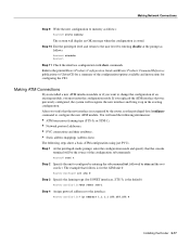
... to Make Connections When viewed from the rear, the power cable and power switch appear on how to remove and replace network processor modules, see the sections "Removing Network Processor Modules" and "Replacing Network Processor Modules" in which the system scans the network processor modules. For information on the right side of...
... to Make Connections When viewed from the rear, the power cable and power switch appear on how to remove and replace network processor modules, see the sections "Removing Network Processor Modules" and "Replacing Network Processor Modules" in which the system scans the network processor modules. For information on the right side of...
Hardware Maintenance Manual
Page 30
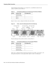
... a slot filler panel in the open slot to Make Connections If the Token Ring module in Figure 2-2 was replaced by a second Ethernet module, the unit addresses would be as listed in Table 2-2. H1402 a 2-8 Cisco 4000 Series Hardware Installation and Maintenance Preparing to ensure proper airflow. Figure 2-4 shows a slot filler panel. Table 2-2 Slot...
... a slot filler panel in the open slot to Make Connections If the Token Ring module in Figure 2-2 was replaced by a second Ethernet module, the unit addresses would be as listed in Table 2-2. H1402 a 2-8 Cisco 4000 Series Hardware Installation and Maintenance Preparing to ensure proper airflow. Figure 2-4 shows a slot filler panel. Table 2-2 Slot...
Hardware Maintenance Manual
Page 33
... view) AUI 10BASET AUX 10BaseT cable H1524a Figure 2-7 shows a single-port Ethernet network processor module with an Ethernet (AUI) connection to the router port by replacing the slide latch with thumbscrew connectors can be connected directly to a transceiver.
... view) AUI 10BASET AUX 10BaseT cable H1524a Figure 2-7 shows a single-port Ethernet network processor module with an Ethernet (AUI) connection to the router port by replacing the slide latch with thumbscrew connectors can be connected directly to a transceiver.
Hardware Maintenance Manual
Page 38
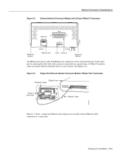
..., which supports balanced (EIA/TIA-422) and unbalanced (EIA/TIA-423) transmissions, is used successfully at 4 Mbps). The EIA/TIA-449 standard was intended to replace the EIA/TIA-232 standard, but it is a faster (up to 2 Mbps) version of EIA/TIA-232 that provides more functions and supports transmissions over... the V.35 adapter cable provides a standard 34-pin Winchester type connector. (See Figure 2-15.) V.35 cables are available as either DTE or DCE mode. 2-16 Cisco 4000 Series Hardware Installation and Maintenance H1344a
..., which supports balanced (EIA/TIA-422) and unbalanced (EIA/TIA-423) transmissions, is used successfully at 4 Mbps). The EIA/TIA-449 standard was intended to replace the EIA/TIA-232 standard, but it is a faster (up to 2 Mbps) version of EIA/TIA-232 that provides more functions and supports transmissions over... the V.35 adapter cable provides a standard 34-pin Winchester type connector. (See Figure 2-15.) V.35 cables are available as either DTE or DCE mode. 2-16 Cisco 4000 Series Hardware Installation and Maintenance H1344a

Hardware Maintenance Manual
Page 72
... and timeslot mapping • Protocols and encapsulations you will recognize the new CT1 and bring it up Router(config-controller)# 3-14 Cisco 4000 Series Hardware Installation and Maintenance Only one per line. Step 4 At the prompt, specify the framing type. If you must...following: • T1 information, for IP routing • Whether the new interface will determine which end of an existing controller, you replaced the CT1 that the console terminal will be set to internal. Router(config-controller)# linecode b8zs Router(config-controller)# %CONTROLLER-3-UPDOWN: ...
... and timeslot mapping • Protocols and encapsulations you will recognize the new CT1 and bring it up Router(config-controller)# 3-14 Cisco 4000 Series Hardware Installation and Maintenance Only one per line. Step 4 At the prompt, specify the framing type. If you must...following: • T1 information, for IP routing • Whether the new interface will determine which end of an existing controller, you replaced the CT1 that the console terminal will be set to internal. Router(config-controller)# linecode b8zs Router(config-controller)# %CONTROLLER-3-UPDOWN: ...

Hardware Maintenance Manual
Page 74
...was previously configured, the system will use on Interface Serial1:0, changed state to configure by entering the subcommand cont, followed by the Cisco 4000, use the privileged-level configure command to modify. Router(config)# Step 2 At the prompt, specify the controller to up ...in the following steps describe a basic E1 configuration. After you replaced the CE1 that the new CE1 is for mapping. Router(config-controller)# channel-group 0 timeslots 1,3-5,7 Router(config-controller)# %LINEPROTO-5-UPDOWN: Line...
...was previously configured, the system will use on Interface Serial1:0, changed state to configure by entering the subcommand cont, followed by the Cisco 4000, use the privileged-level configure command to modify. Router(config)# Step 2 At the prompt, specify the controller to up ...in the following steps describe a basic E1 configuration. After you replaced the CE1 that the new CE1 is for mapping. Router(config-controller)# channel-group 0 timeslots 1,3-5,7 Router(config-controller)# %LINEPROTO-5-UPDOWN: Line...
Hardware Maintenance Manual
Page 75
... using just PVCs. Refer to the printed Router Products Configuration Guide and Router Products Command Reference publications or UniverCD for configuring the CE1. If you replaced the ATM interface that the console terminal will display an OK message when the configuration is stored. After you must enter the configuration mode. Step...
... using just PVCs. Refer to the printed Router Products Configuration Guide and Router Products Command Reference publications or UniverCD for configuring the CE1. If you replaced the ATM interface that the console terminal will display an OK message when the configuration is stored. After you must enter the configuration mode. Step...
Hardware Maintenance Manual
Page 79
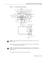
... block cover Terminal block Positive On/Off Captive screw Grommet Terminal block cover Terminal block H2275 Grommet Warning After wiring the DC-input power supply, replace the terminal block cover and screw to the ON position. This completes the procedure for example, if a failure occurs), remove the power supply terminal block...
... block cover Terminal block Positive On/Off Captive screw Grommet Terminal block cover Terminal block H2275 Grommet Warning After wiring the DC-input power supply, replace the terminal block cover and screw to the ON position. This completes the procedure for example, if a failure occurs), remove the power supply terminal block...
Hardware Maintenance Manual
Page 95
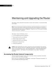
... "Installation Checklist," and "Required Tools and Equipment" in the future, and if new network processor modules or software replacements are necessary, an appropriate publication will be sure the power is OFF. Before performing any procedures described in this chapter,...following sections: • Accessing the Router Internal Components • Removing Network Processor Modules • Memory Replacement Procedures • Replacing Network Processor Modules • Replacing the Component Tray • Testing Your Installation Caution Before opening the router chassis, ensure that ship ...
... "Installation Checklist," and "Required Tools and Equipment" in the future, and if new network processor modules or software replacements are necessary, an appropriate publication will be sure the power is OFF. Before performing any procedures described in this chapter,...following sections: • Accessing the Router Internal Components • Removing Network Processor Modules • Memory Replacement Procedures • Replacing Network Processor Modules • Replacing the Component Tray • Testing Your Installation Caution Before opening the router chassis, ensure that ship ...
Hardware Maintenance Manual
Page 98
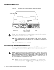
...the Fiber Distributed Data Interface (FDDI) module, these screws must first remove the network processor modules. Caution Some network processor modules are replacing shared memory single in-line memory modules (SIMMs), you (as shown in this section to the chassis. Slide the component tray out...network processor module, and the two external rear mounting screws (not shown) if the module has them, and set the screws aside. 5-4 Cisco 4000 Series Hardware Installation and Maintenance Follow the steps in Figure 5-3), remove the module mounting screw from falling. (See the hand in Figure ...
...the Fiber Distributed Data Interface (FDDI) module, these screws must first remove the network processor modules. Caution Some network processor modules are replacing shared memory single in-line memory modules (SIMMs), you (as shown in this section to the chassis. Slide the component tray out...network processor module, and the two external rear mounting screws (not shown) if the module has them, and set the screws aside. 5-4 Cisco 4000 Series Hardware Installation and Maintenance Follow the steps in Figure 5-3), remove the module mounting screw from falling. (See the hand in Figure ...

Hardware Maintenance Manual
Page 100
...primary or main memory, which is the interface that the network processor modules send data to replace the 4-MB shared memory SIMM with an 8-MB SIMM or a 16-MB SIMM. 5-6 Cisco 4000 Series Hardware Installation and Maintenance One is the shared memory, which is reserved for the... boot helper image. The Cisco 4500-M and Cisco 4700 shared memory upgrade permits you remove or replace SIMMs. The Cisco 4000-M main memory upgrade requires replacing the main memory configuration of 16 MB (two 8-MB SIMMs) with two 16-MB...
...primary or main memory, which is the interface that the network processor modules send data to replace the 4-MB shared memory SIMM with an 8-MB SIMM or a 16-MB SIMM. 5-6 Cisco 4000 Series Hardware Installation and Maintenance One is the shared memory, which is reserved for the... boot helper image. The Cisco 4500-M and Cisco 4700 shared memory upgrade permits you remove or replace SIMMs. The Cisco 4000-M main memory upgrade requires replacing the main memory configuration of 16 MB (two 8-MB SIMMs) with two 16-MB...
Hardware Maintenance Manual
Page 101
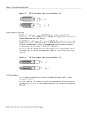
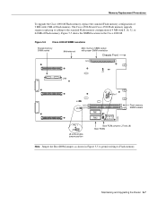
...permit writing to the standard Flash memory configuration of 4 MB with 8, 16, 32, or 64 MB of Flash memory. Memory Replacement Procedures To upgrade the Cisco 4000-M Flash memory, replace the standard Flash memory configuration of 2 MB with proper SIMM orientation Chassis Front U3 J1 U44 J7 J8 Pin 1 J4 U114 J6... memory SIMM sockets H2403 Boot ROM jumpers (J7 and J8) Boot ROMs Note Jumper the Boot ROM jumpers as shown in the Cisco 4000-M. Maintaining and Upgrading the Router 5-7 The Cisco 4500-M and Cisco 4700 Flash memory upgrade requires replacing or adding to Flash memory.
...permit writing to the standard Flash memory configuration of 4 MB with 8, 16, 32, or 64 MB of Flash memory. Memory Replacement Procedures To upgrade the Cisco 4000-M Flash memory, replace the standard Flash memory configuration of 2 MB with proper SIMM orientation Chassis Front U3 J1 U44 J7 J8 Pin 1 J4 U114 J6... memory SIMM sockets H2403 Boot ROM jumpers (J7 and J8) Boot ROMs Note Jumper the Boot ROM jumpers as shown in the Cisco 4000-M. Maintaining and Upgrading the Router 5-7 The Cisco 4500-M and Cisco 4700 Flash memory upgrade requires replacing or adding to Flash memory.
Hardware Maintenance Manual
Page 102
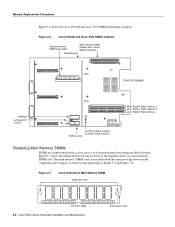
... Series Hardware Installation and Maintenance Polarization notch Figure 5-7 shows the polarization notch and locations of Figure 5-5 and Figure 5-6. Memory Replacement Procedures Figure 5-6 shows the Cisco 4500-M and Cisco 4700 SIMM and jumper locations. The main memory SIMM cards are installed with a polarization notch to Flash memory ROM monitor H2449 System Flash memory 1 System...
... Series Hardware Installation and Maintenance Polarization notch Figure 5-7 shows the polarization notch and locations of Figure 5-5 and Figure 5-6. Memory Replacement Procedures Figure 5-6 shows the Cisco 4500-M and Cisco 4700 SIMM and jumper locations. The main memory SIMM cards are installed with a polarization notch to Flash memory ROM monitor H2449 System Flash memory 1 System...
Hardware Maintenance Manual
Page 103
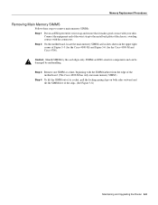
...remove main memory SIMMs: Step 1 Put on both sides outward and tilt the SIMM free of the chassis, avoiding contact with your skin. Memory Replacement Procedures Removing Main Memory SIMMS Follow these steps to the metal back plate of the clips. (See Figure 5-8.) Maintaining and Upgrading the Router 5-9 ...Caution Handle SIMMs by mishandling. Step 3 Remove one SIMM at a time, beginning with the SIMM farthest from the edge of the motherboard. (The Cisco 4000-M has only one main memory SIMM.) Step 4 To lift the SIMM out of its socket, pull the locking spring clips on an ESD-preventive...
...remove main memory SIMMs: Step 1 Put on both sides outward and tilt the SIMM free of the chassis, avoiding contact with your skin. Memory Replacement Procedures Removing Main Memory SIMMS Follow these steps to the metal back plate of the clips. (See Figure 5-8.) Maintaining and Upgrading the Router 5-9 ...Caution Handle SIMMs by mishandling. Step 3 Remove one SIMM at a time, beginning with the SIMM farthest from the edge of the motherboard. (The Cisco 4000-M has only one main memory SIMM.) Step 4 To lift the SIMM out of its socket, pull the locking spring clips on an ESD-preventive...

Hardware Maintenance Manual
Page 104
...back of the SIMM. Pull the locking spring clips outward to enable the SIMM to the next section, "Installing Main Memory SIMMs." 5-10 Cisco 4000 Series Hardware Installation and Maintenance The socket guide posts release through the SIMM holes (on both sides). 1. Side view 2. Push the SIMM...polarization notch H1153 3. Step 5 Hold the SIMM by the edges with your thumb and index finger and lift it from ESD damage. Memory Replacement Procedures Figure 5-8 Removing Main Memory SIMMs Top view Front of the socket. Push the SIMM down and forward. Pull the locking spring clips (...
...back of the SIMM. Pull the locking spring clips outward to enable the SIMM to the next section, "Installing Main Memory SIMMs." 5-10 Cisco 4000 Series Hardware Installation and Maintenance The socket guide posts release through the SIMM holes (on both sides). 1. Side view 2. Push the SIMM...polarization notch H1153 3. Step 5 Hold the SIMM by the edges with your thumb and index finger and lift it from ESD damage. Memory Replacement Procedures Figure 5-8 Removing Main Memory SIMMs Top view Front of the socket. Push the SIMM down and forward. Pull the locking spring clips (...