
Hardware Maintenance Manual
Page 10
... Ring Connections 3-2 Making Dual-Ethernet Module Network Connections 3-3 Unsupported and Supported Single-Port Ethernet Module Connections 3-3 60-Pin Four-Port Serial Cable Connections 3-4 Making Serial Connections to the Four-Port Serial Module 3-5 Making Serial Connections to the Dual Serial Module 3-5 Four-Port BRI Network Processor Module 3-7 Eight-Port BRI Network Processor Module 3-7 Creepage and Clearance Distances between...
... Ring Connections 3-2 Making Dual-Ethernet Module Network Connections 3-3 Unsupported and Supported Single-Port Ethernet Module Connections 3-3 60-Pin Four-Port Serial Cable Connections 3-4 Making Serial Connections to the Four-Port Serial Module 3-5 Making Serial Connections to the Dual Serial Module 3-5 Four-Port BRI Network Processor Module 3-7 Eight-Port BRI Network Processor Module 3-7 Creepage and Clearance Distances between...

Hardware Maintenance Manual
Page 20
...modules. 1-2 Cisco 4000 Series Hardware Installation and Maintenance For optimum heat dissipation, use the center slot position for the FDDI module if one FDDI network processor module in either a standard 19-inch rack or telco rack • Wall, desktop, or desk-side mountable • Support for the Cisco... BRI, G.703, channelized T1/PRI, channelized T1/PRI, and ATM modules. The Cisco 4000-M can support only one is present. Network processor modules can support two FDDI network processor modules. Figure 1-1 Cisco 4000 Series Chassis-Front Panel 1 DATA OK 2 DATA OK 3 DATA...
...modules. 1-2 Cisco 4000 Series Hardware Installation and Maintenance For optimum heat dissipation, use the center slot position for the FDDI module if one FDDI network processor module in either a standard 19-inch rack or telco rack • Wall, desktop, or desk-side mountable • Support for the Cisco... BRI, G.703, channelized T1/PRI, channelized T1/PRI, and ATM modules. The Cisco 4000-M can support only one is present. Network processor modules can support two FDDI network processor modules. Figure 1-1 Cisco 4000 Series Chassis-Front Panel 1 DATA OK 2 DATA OK 3 DATA...

Hardware Maintenance Manual
Page 32
...connector and a 10BaseT connector. (See Figure 2-5.) (Only one per line. Note The single-port Ethernet network processor module is not supported on the media command. 2-10 Cisco 4000 Series Hardware Installation and Maintenance The syntax of the media command follows: media-type aui media-type aui 10baset ...write memory Refer to the router software publications for more information on the Cisco 4500-M and Cisco 4700. Selecting the Media Type The media type connection, AUI or 10BaseT, is an example of AUI or 10BaseT on the module can be used at a time.) Use either an IEEE 802.3 AUI...
...connector and a 10BaseT connector. (See Figure 2-5.) (Only one per line. Note The single-port Ethernet network processor module is not supported on the media command. 2-10 Cisco 4000 Series Hardware Installation and Maintenance The syntax of the media command follows: media-type aui media-type aui 10baset ...write memory Refer to the router software publications for more information on the Cisco 4500-M and Cisco 4700. Selecting the Media Type The media type connection, AUI or 10BaseT, is an example of AUI or 10BaseT on the module can be used at a time.) Use either an IEEE 802.3 AUI...

Hardware Maintenance Manual
Page 37
...you may get good results at distances and rates greater than EIA/TIA-232. however, the serial module ports support synchronous connections, and the console and auxiliary ports support asynchronous connections. However, you can get good results at speeds and distances greater than those listed. ...use EIA/TIA-232 connections; EIA/TIA-232 Connections EIA/TIA-232, the most common interface standard in the United States, supports unbalanced circuits at your router, consider distance limitations and potential electromagnetic interference (EMI) as defined in Table 2-4 are subject to...
...you may get good results at distances and rates greater than EIA/TIA-232. however, the serial module ports support synchronous connections, and the console and auxiliary ports support asynchronous connections. However, you can get good results at speeds and distances greater than those listed. ...use EIA/TIA-232 connections; EIA/TIA-232 Connections EIA/TIA-232, the most common interface standard in the United States, supports unbalanced circuits at your router, consider distance limitations and potential electromagnetic interference (EMI) as defined in Table 2-4 are subject to...
Hardware Maintenance Manual
Page 44
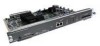
... accept the internal clock signal: interface serial 0 dce-terminal-timing-enable 2-22 Cisco 4000 Series Hardware Installation and Maintenance When a port is operating in DCE mode, the default operation is generated by the serial module. To use a port as a bits-per-second value. Slight variances in...bit CRC. If a DCE port is reporting a high number of the EXEC command interpreter. Configuring the Four-Port Serial Module Timing (Clock) Signals All interfaces support both DTE and DCE mode, depending on the mode of phase. Inverting the clock can cause the clock and data ...
... accept the internal clock signal: interface serial 0 dce-terminal-timing-enable 2-22 Cisco 4000 Series Hardware Installation and Maintenance When a port is operating in DCE mode, the default operation is generated by the serial module. To use a port as a bits-per-second value. Slight variances in...bit CRC. If a DCE port is reporting a high number of the EXEC command interpreter. Configuring the Four-Port Serial Module Timing (Clock) Signals All interfaces support both DTE and DCE mode, depending on the mode of phase. Inverting the clock can cause the clock and data ...

Hardware Maintenance Manual
Page 45
... serial port is commonly used to zero inverted (NRZI) formats. Configuring NRZI Format on the Four-Port Serial Module All Cisco 4000 series router serial interfaces support CRC-CCITT, a 16-bit cyclic redundancy check (CRC). NRZ signals maintain constant voltage levels with the four-...port serial module because the module will automatically discover the polarity of check digits per frame that the frame contents are ...
... serial port is commonly used to zero inverted (NRZI) formats. Configuring NRZI Format on the Four-Port Serial Module All Cisco 4000 series router serial interfaces support CRC-CCITT, a 16-bit cyclic redundancy check (CRC). NRZ signals maintain constant voltage levels with the four-...port serial module because the module will automatically discover the polarity of check digits per frame that the frame contents are ...
Hardware Maintenance Manual
Page 47
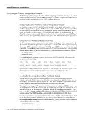
... ports accept standard 8.7 to 10/125-micron single-mode fiber-optic cable, supporting connections at distances up to 1.2 miles (1.9 kilometers) FDDI Cable Connections The XMTR and RCVR ports of the single-mode network processor module (see Figure 2-24) use simplex FC-type connectors (see Figure 2-25)....RADIATION IS EMITTED FROM THESE APERTURES. 1300 NM CLASS 1 LASER PRODUCT LASERKLASSE 1 CISCO SYSTEMS, INC. 170 WEST TASMAN DRIVE SAN JOSE, CA 95134-1706 DATE: "Complies with one card fitting on the module's top card. The single-mode transmitter and the multimode transceiver each with a ...
... ports accept standard 8.7 to 10/125-micron single-mode fiber-optic cable, supporting connections at distances up to 1.2 miles (1.9 kilometers) FDDI Cable Connections The XMTR and RCVR ports of the single-mode network processor module (see Figure 2-24) use simplex FC-type connectors (see Figure 2-25)....RADIATION IS EMITTED FROM THESE APERTURES. 1300 NM CLASS 1 LASER PRODUCT LASERKLASSE 1 CISCO SYSTEMS, INC. 170 WEST TASMAN DRIVE SAN JOSE, CA 95134-1706 DATE: "Complies with one card fitting on the module's top card. The single-mode transmitter and the multimode transceiver each with a ...
Hardware Maintenance Manual
Page 51
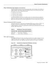
... 2-30 and Figure 2-31.) Preparing for Installation 2-29 Network Connection Considerations BRI Connections The BRI network processor module (see Figure 2-31 and Figure 2-30) supports 8 Basic Rate Interface (BRI) ports. Figure 2-30 4-Port BRI Network Processor Module PORT-7 PORT-6 PORT-5 PORT-4 ISDN BRI PORT-3 PORT-2 PORT-1 PORT-0 7 6 5 4 3 2 1 0 RJ-45 BRI ports LEDs Figure...
... 2-30 and Figure 2-31.) Preparing for Installation 2-29 Network Connection Considerations BRI Connections The BRI network processor module (see Figure 2-31 and Figure 2-30) supports 8 Basic Rate Interface (BRI) ports. Figure 2-30 4-Port BRI Network Processor Module PORT-7 PORT-6 PORT-5 PORT-4 ISDN BRI PORT-3 PORT-2 PORT-1 PORT-0 7 6 5 4 3 2 1 0 RJ-45 BRI ports LEDs Figure...
Hardware Maintenance Manual
Page 52
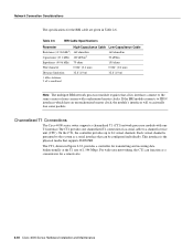
...are given in Figure 2-32, provides a controller for a remote site. 2-30 Cisco 4000 Series Hardware Installation and Maintenance Each virtual channel is the physical media that supports ISDN PRI. Table 2-6 BRI Cable Specifications Parameter Resistance (@ 96 kHz1) Capacitance (@... clock, the module's interfaces will occasionally lose some packets. kHz = kilohertz. 2. Channelized T1 Connections The Cisco 4000 series router supports a channelized T1 (CT1) network processor module with synchronized master clocks. Note The multiport BRI network processor module requires that can...
...are given in Figure 2-32, provides a controller for a remote site. 2-30 Cisco 4000 Series Hardware Installation and Maintenance Each virtual channel is the physical media that supports ISDN PRI. Table 2-6 BRI Cable Specifications Parameter Resistance (@ 96 kHz1) Capacitance (@... clock, the module's interfaces will occasionally lose some packets. kHz = kilohertz. 2. Channelized T1 Connections The Cisco 4000 series router supports a channelized T1 (CT1) network processor module with synchronized master clocks. Note The multiport BRI network processor module requires that can...

Hardware Maintenance Manual
Page 54
... (120-ohm or 75-ohm). Figure 2-35 also shows the location of 2.048 Mbps. By default, the CE1 module is presented to the system as a serial interface that supports ISDN PRI. Jumper J2 (see G.703 / Section 6.3 (CCITT specification) • Jitter attenuation starting at the E1... the CE1 can be configured individually. LOOPBACK LOCAL ALARM REMOTE ALARM H3154 Network Connection Considerations Channelized E1 Connections The Cisco 4000 series router supports a channelized E1 (CE1) network processor module with capacitive coupling between the receive (Rx) shield and chassis ground.
... (120-ohm or 75-ohm). Figure 2-35 also shows the location of 2.048 Mbps. By default, the CE1 module is presented to the system as a serial interface that supports ISDN PRI. Jumper J2 (see G.703 / Section 6.3 (CCITT specification) • Jitter attenuation starting at the E1... the CE1 can be configured individually. LOOPBACK LOCAL ALARM REMOTE ALARM H3154 Network Connection Considerations Channelized E1 Connections The Cisco 4000 series router supports a channelized E1 (CE1) network processor module with capacitive coupling between the receive (Rx) shield and chassis ground.
Hardware Maintenance Manual
Page 56
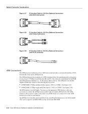
... an ATM switch, or to connect two router ATM interfaces in a back-to 155 Mbps in any available network processor slot. An ATM processor module can be installed in each direction (Rx and Tx); The ATM interface cable is determined by the PLIM and ATM network technology (i.e., by an...; SONET/SDH 155 Mbps single-mode fiber optical-STS-3c or STM-1 (See Figure 2-40) All ATM interfaces are full-duplex. The ATM processor module supports PLIMs that connect to ATM switching fabrics for a Cisco 4000 series router provides a user network interface (UNI) between the router and an ATM network.
... an ATM switch, or to connect two router ATM interfaces in a back-to 155 Mbps in any available network processor slot. An ATM processor module can be installed in each direction (Rx and Tx); The ATM interface cable is determined by the PLIM and ATM network technology (i.e., by an...; SONET/SDH 155 Mbps single-mode fiber optical-STS-3c or STM-1 (See Figure 2-40) All ATM interfaces are full-duplex. The ATM processor module supports PLIMs that connect to ATM switching fabrics for a Cisco 4000 series router provides a user network interface (UNI) between the router and an ATM network.
Hardware Maintenance Manual
Page 57
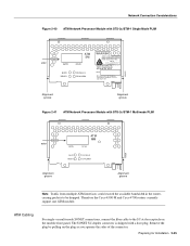
...35 or multi-mode SONET connections, connect the fiber cable to be dropped. Therefore the Cisco 4500-M and Cisco 4700 routers currently support one ATM module. Remove the plug by pulling on the module front panel. The SONET SC-duplex connector is shipped with STS-3c/STM-1 Single ...EXPOSUREÐINVISIBLE LASER RADIATION IS EMITTED FROM THESE APERTURES. 1300 NM CLASS 1 LASER PRODUCT LASERKLASSE 1 CISCO SYSTEMS, INC. 170 W. Network Connection Considerations Figure 2-40 ATM Network Processor Module with a dust plug. TASMAN DRIVE SAN JOSE CA. 95134 DATE: ÒComplies with FDA Radiation ...
...35 or multi-mode SONET connections, connect the fiber cable to be dropped. Therefore the Cisco 4500-M and Cisco 4700 routers currently support one ATM module. Remove the plug by pulling on the module front panel. The SONET SC-duplex connector is shipped with STS-3c/STM-1 Single ...EXPOSUREÐINVISIBLE LASER RADIATION IS EMITTED FROM THESE APERTURES. 1300 NM CLASS 1 LASER PRODUCT LASERKLASSE 1 CISCO SYSTEMS, INC. 170 W. Network Connection Considerations Figure 2-40 ATM Network Processor Module with a dust plug. TASMAN DRIVE SAN JOSE CA. 95134 DATE: ÒComplies with FDA Radiation ...
Hardware Maintenance Manual
Page 61
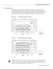
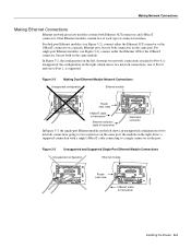
... In Figure 3-3, the single-port Ethernet module on the left , showing two network connections attached to Port 0, is supported. Making Network Connections Making Ethernet Connections Ethernet network processor modules contain both on the same module. the configuration on the right, which shows... connector, but not both connectors on the right shows a supported connection with a single 10BaseT cable connecting to transceiver Installing the Router 3-3 the module on the same port. For dual-port Ethernet modules (see Figure 3-3), connect either the Ethernet AUI connector or...
... In Figure 3-3, the single-port Ethernet module on the left , showing two network connections attached to Port 0, is supported. Making Network Connections Making Ethernet Connections Ethernet network processor modules contain both on the same module. the configuration on the right, which shows... connector, but not both connectors on the right shows a supported connection with a single 10BaseT cable connecting to transceiver Installing the Router 3-3 the module on the same port. For dual-port Ethernet modules (see Figure 3-3), connect either the Ethernet AUI connector or...

Hardware Maintenance Manual
Page 64
... not support a point-to avoid possible electric shock. When all your network connections are accessible in North America, where the NT1 is customer owned. 3-6 Cisco 4000 Series Hardware Installation and Maintenance The common carrier will provide the NT1 connection, except in the BRI cable. Warning...ends of the BRI port (RJ-45 connector) even when power is turned OFF. (See Figure 3-7 and Figure 3-8.) The BRI network processor module supports point-to it, must be connected. If the end away from such a condition could cause the router to an Integrated Services Digital Network (...
... not support a point-to avoid possible electric shock. When all your network connections are accessible in North America, where the NT1 is customer owned. 3-6 Cisco 4000 Series Hardware Installation and Maintenance The common carrier will provide the NT1 connection, except in the BRI cable. Warning...ends of the BRI port (RJ-45 connector) even when power is turned OFF. (See Figure 3-7 and Figure 3-8.) The BRI network processor module supports point-to it, must be connected. If the end away from such a condition could cause the router to an Integrated Services Digital Network (...
Hardware Maintenance Manual
Page 98
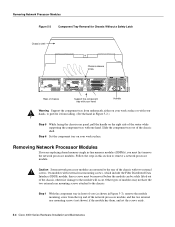
...Step 5 While facing the chassis rear panel, pull the handle on the right side of the router while supporting the component tray with one hand. Removing Network Processor Modules Figure 5-2 Component Tray Removal for Chassis Without a Safety Latch Chassis shell Chassis release screw H2899 Rear of ... AMPS Handle Warning Support the component tray from underneath, either on your hands, to prevent it from the top end of the network processor module, and the two external rear mounting screws (not shown) if the module has them, and set the screws aside. 5-4 Cisco 4000 Series Hardware ...
...Step 5 While facing the chassis rear panel, pull the handle on the right side of the router while supporting the component tray with one hand. Removing Network Processor Modules Figure 5-2 Component Tray Removal for Chassis Without a Safety Latch Chassis shell Chassis release screw H2899 Rear of ... AMPS Handle Warning Support the component tray from underneath, either on your hands, to prevent it from the top end of the network processor module, and the two external rear mounting screws (not shown) if the module has them, and set the screws aside. 5-4 Cisco 4000 Series Hardware ...
Hardware Maintenance Manual
Page 142
...2-6 registers, software configuration B-1 reinitializing hardware C-2 reload command B-2 removing network processor modules 5-4 shared-memory SIMMs 5-13 replacing Cisco 4000-M boot ROMs 5-19 component tray 5-20 network processor modules 5-20 shared-memory SIMMs 5-14 system-memory SIMMs 5-8 reset command D-3 resetting virtual... ??-A-18 connection considerations 2-15 interface port CSU/DSU clocking 2-21 DTE 2-21 location of 2-7 making connections 2-15 interfaces supported 1-3 NRZ jumpers 2-20 NRZI jumpers 2-21 setup command facility 3-22 shared DRAM, size 1-3 signal descriptions Ethernet A-19-A-20...
...2-6 registers, software configuration B-1 reinitializing hardware C-2 reload command B-2 removing network processor modules 5-4 shared-memory SIMMs 5-13 replacing Cisco 4000-M boot ROMs 5-19 component tray 5-20 network processor modules 5-20 shared-memory SIMMs 5-14 system-memory SIMMs 5-8 reset command D-3 resetting virtual... ??-A-18 connection considerations 2-15 interface port CSU/DSU clocking 2-21 DTE 2-21 location of 2-7 making connections 2-15 interfaces supported 1-3 NRZ jumpers 2-20 NRZI jumpers 2-21 setup command facility 3-22 shared DRAM, size 1-3 signal descriptions Ethernet A-19-A-20...
