
Hardware Maintenance Manual
Page 9
...Figure 2-24 Figure 2-25 Figure 2-26 Figure 2-27 Figure 2-28 Figure 2-29 Figure 2-30 Figure 2-31 Figure 2-32 Cisco 4000 Series Chassis-Front Panel 1-2 Cisco 4000 Series Memory Systems and Software Images 1-4 Installation Checklist 2-5 Router-Rear View Showing Slot Numbering and Interface Ports 2-7 Router-...26 Multimode FDDI Network Interface Connector, MIC Type 2-26 Dual-Attachment Multimode FDDI Module-End View 2-27 Dual-Attachment FDDI Optical Bypass Switch and PHY Connections 2-27 Single-Attachment Multimode FDDI Module-End View 2-28 4-Port BRI Network Processor Module 2-29 8-Port BRI Network...
...Figure 2-24 Figure 2-25 Figure 2-26 Figure 2-27 Figure 2-28 Figure 2-29 Figure 2-30 Figure 2-31 Figure 2-32 Cisco 4000 Series Chassis-Front Panel 1-2 Cisco 4000 Series Memory Systems and Software Images 1-4 Installation Checklist 2-5 Router-Rear View Showing Slot Numbering and Interface Ports 2-7 Router-...26 Multimode FDDI Network Interface Connector, MIC Type 2-26 Dual-Attachment Multimode FDDI Module-End View 2-27 Dual-Attachment FDDI Optical Bypass Switch and PHY Connections 2-27 Single-Attachment Multimode FDDI Module-End View 2-28 4-Port BRI Network Processor Module 2-29 8-Port BRI Network...
Hardware Maintenance Manual
Page 24
...another person to get caught in which you can weld the metal object to the system. - Working near power supplies - then take appropriate action. 2-2 Cisco 4000 Series Hardware Installation and Maintenance Metal objects will help . - Installing or removing a chassis - Safety with Electricity Follow these guidelines when working . ... connected to shut the power off. • Before working on equipment powered by electricity: • Locate the emergency power-off switch in the room in the chassis. Determine if the person needs rescue breathing or external cardiac compressions;
...another person to get caught in which you can weld the metal object to the system. - Working near power supplies - then take appropriate action. 2-2 Cisco 4000 Series Hardware Installation and Maintenance Metal objects will help . - Installing or removing a chassis - Safety with Electricity Follow these guidelines when working . ... connected to shut the power off. • Before working on equipment powered by electricity: • Locate the emergency power-off switch in the room in the chassis. Determine if the person needs rescue breathing or external cardiac compressions;

Hardware Maintenance Manual
Page 28
.../TIA-449, or EIA-530 electrical interface. • Ethernet transceiver. • Token Ring media attachment unit (MAU). • Optical bypass switch or concentrator for multimode Fiber Distributed Data Interface (FDDI) connections. 2-6 Cisco 4000 Series Hardware Installation and Maintenance Use the Installation Checklist to the router. Additional network processor modules - Site Log Site...
.../TIA-449, or EIA-530 electrical interface. • Ethernet transceiver. • Token Ring media attachment unit (MAU). • Optical bypass switch or concentrator for multimode Fiber Distributed Data Interface (FDDI) connections. 2-6 Cisco 4000 Series Hardware Installation and Maintenance Use the Installation Checklist to the router. Additional network processor modules - Site Log Site...

Hardware Maintenance Manual
Page 29
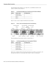
...modules in Figure 2-2 are as listed in which the system scans the network processor modules. The lowest unit number of the power cable and switch. (See Figure 2-2.) Figure 2-2 Router-Rear View Showing Slot Numbering and Interface Ports Slot 3 Token Ring port 10BaseT Chassis Serial interface ports...release screw Slot 1 Ethernet port Slot 2 Dual serial module H1033a Token Ring module Ethernet module Auxiliary port Console port Power On/off switch Slot Numbering The chassis contains slots for each module interface type and numbering from right to left . Any module can be moved ...
...modules in Figure 2-2 are as listed in which the system scans the network processor modules. The lowest unit number of the power cable and switch. (See Figure 2-2.) Figure 2-2 Router-Rear View Showing Slot Numbering and Interface Ports Slot 3 Token Ring port 10BaseT Chassis Serial interface ports...release screw Slot 1 Ethernet port Slot 2 Dual serial module H1033a Token Ring module Ethernet module Auxiliary port Console port Power On/off switch Slot Numbering The chassis contains slots for each module interface type and numbering from right to left . Any module can be moved ...
Hardware Maintenance Manual
Page 30
... 2 Auxiliary port Serial 0 Console port The unit numbering of these modules would be as listed in Table 2-3. H1402 a 2-8 Cisco 4000 Series Hardware Installation and Maintenance INPUT 100-240VAC 50/60HZ 3.0-1.5 AMPS Power On/off switch Table 2-3 Slot No. 1 2 3 Unit Numbering Addresses for Dual Serial and Two Ethernet Modules Interface Type Serial Port...
... 2 Auxiliary port Serial 0 Console port The unit numbering of these modules would be as listed in Table 2-3. H1402 a 2-8 Cisco 4000 Series Hardware Installation and Maintenance INPUT 100-240VAC 50/60HZ 3.0-1.5 AMPS Power On/off switch Table 2-3 Slot No. 1 2 3 Unit Numbering Addresses for Dual Serial and Two Ethernet Modules Interface Type Serial Port...
Hardware Maintenance Manual
Page 49
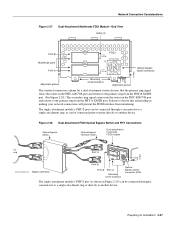
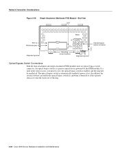
...network connections will prevent the FDDI interface from the PHY-A XMTR port. Figure 2-28 Dual-Attachment FDDI Optical Bypass Switch and PHY Connections Optical bypass switch Optical bypass interface cable Dual-attachment multimode FDDI module To ring PHY-A PHY-B PHY-A RING OP FDDI OPT-BYPASS... RING OP H1405a Bypass operation PHY-B PHY-B PHY-A Mounting screw locations Optical bypass switch connector (DIN) The single-attachment module's PHY-S port (as shown in Figure 2-29) can be connected through a concentrator to a single-...
...network connections will prevent the FDDI interface from the PHY-A XMTR port. Figure 2-28 Dual-Attachment FDDI Optical Bypass Switch and PHY Connections Optical bypass switch Optical bypass interface cable Dual-attachment multimode FDDI module To ring PHY-A PHY-B PHY-A RING OP FDDI OPT-BYPASS... RING OP H1405a Bypass operation PHY-B PHY-B PHY-A Mounting screw locations Optical bypass switch connector (DIN) The single-attachment module's PHY-S port (as shown in Figure 2-29) can be connected through a concentrator to a single-...
Hardware Maintenance Manual
Page 50
... enabled, and the ring will be unaffected. In addition, the system software can enable the optical bypass switch if a problem is lost , the optical bypass switch is a passive optical device powered by the FDDI module. Network Connection Considerations Figure 2-29 Single-Attachment Multimode FDDI ... Optical Bypass Switch Connections Both the dual-attachment and single-attachment FDDI modules have an optical bypass switch connector. The optical bypass switch is automatically enabled if power is detected or if the operator chooses to take the router out of the ring. 2-28 Cisco 4000 Series...
... enabled, and the ring will be unaffected. In addition, the system software can enable the optical bypass switch if a problem is lost , the optical bypass switch is a passive optical device powered by the FDDI module. Network Connection Considerations Figure 2-29 Single-Attachment Multimode FDDI ... Optical Bypass Switch Connections Both the dual-attachment and single-attachment FDDI modules have an optical bypass switch connector. The optical bypass switch is automatically enabled if power is detected or if the operator chooses to take the router out of the ring. 2-28 Cisco 4000 Series...
Hardware Maintenance Manual
Page 56
...ATM processor module can be installed in each direction (Rx and Tx); If the middle slot is used to connect your router to an ATM switch, or to connect two router ATM interfaces in a back-to connect the ATM processor module with RJ-45 Connector) H2422 ATM Connections The ...use this slot for a Cisco 4000 series router provides a user network interface (UNI) between the router and an ATM network. The ATM processor module supports PLIMs that connect to 155 Mbps in any available network processor slot. The ATM module provides an interface to ATM switching fabrics for transmitting and ...
...ATM processor module can be installed in each direction (Rx and Tx); If the middle slot is used to connect your router to an ATM switch, or to connect two router ATM interfaces in a back-to connect the ATM processor module with RJ-45 Connector) H2422 ATM Connections The ...use this slot for a Cisco 4000 series router provides a user network interface (UNI) between the router and an ATM network. The ATM processor module supports PLIMs that connect to 155 Mbps in any available network processor slot. The ATM module provides an interface to ATM switching fabrics for transmitting and ...

Hardware Maintenance Manual
Page 66
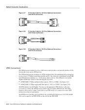
TE refers to terminal terminating layer 1 aspects of Cisco Systems' chassis to either four or eight Basic Access Integrated Switched Digital Networks (ISDN), each at the S reference point. With the loopback RJ-45 connector plug installed in Table 3-2. When... Interface Port Pinout The BRI interface port pinout is shown in a BRI port, use within a range of data communication (gateway and router) chassis supplied by Cisco Systems throughout Europe. Table 3-2 BRI Port Pinout (RJ-45) 8 Pin1 TE2 NT3 Polarity 3 Transmit Receive + 4 Receive Transmit + 5 Receive Transmit - 6 ...
TE refers to terminal terminating layer 1 aspects of Cisco Systems' chassis to either four or eight Basic Access Integrated Switched Digital Networks (ISDN), each at the S reference point. With the loopback RJ-45 connector plug installed in Table 3-2. When... Interface Port Pinout The BRI interface port pinout is shown in a BRI port, use within a range of data communication (gateway and router) chassis supplied by Cisco Systems throughout Europe. Table 3-2 BRI Port Pinout (RJ-45) 8 Pin1 TE2 NT3 Polarity 3 Transmit Receive + 4 Receive Transmit + 5 Receive Transmit - 6 ...
Hardware Maintenance Manual
Page 70
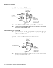
...Single attachment multimode FDDI module RING OP H1575a To concentrator MIC connector PHY-S FDDI OPT-BYPASS PHY-S port Optical bypass switch connector (DIN) Optical bypass interface cable Step 2 When all your network connections are complete, proceed to the section "Connecting to ...Optical bypass interface cable H1573a Step 2 Connect PHY-B on the FDDI module (the top port) to an Optical Bypass Switch" later in this chapter. 3-12 Cisco 4000 Series Hardware Installation and Maintenance Step 3 When all your network connections are complete, proceed to the section "Connecting to...
...Single attachment multimode FDDI module RING OP H1575a To concentrator MIC connector PHY-S FDDI OPT-BYPASS PHY-S port Optical bypass switch connector (DIN) Optical bypass interface cable Step 2 When all your network connections are complete, proceed to the section "Connecting to ...Optical bypass interface cable H1573a Step 2 Connect PHY-B on the FDDI module (the top port) to an Optical Bypass Switch" later in this chapter. 3-12 Cisco 4000 Series Hardware Installation and Maintenance Step 3 When all your network connections are complete, proceed to the section "Connecting to...
Hardware Maintenance Manual
Page 71
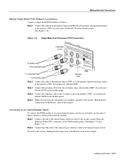
Step 1 Connect one end of the optical bypass interface cable to the optical bypass switch. Step 4 Connect the outgoing cable to the secondary ring to an external optical bypass switch (not included), use the optical bypass interface cable included with the module. B transmit port labeled XMTR. B ...optical bypass interface cable to the six-pin circular Deutsche Industrie-Norm (DIN) connector on the module panel. Connecting to an Optical Bypass Switch To connect the FDDI module to the module's PHY- Installing the Router 3-13 A at the primary ring upstream station) to the ...
Step 1 Connect one end of the optical bypass interface cable to the optical bypass switch. Step 4 Connect the outgoing cable to the secondary ring to an external optical bypass switch (not included), use the optical bypass interface cable included with the module. B transmit port labeled XMTR. B ...optical bypass interface cable to the six-pin circular Deutsche Industrie-Norm (DIN) connector on the module panel. Connecting to an Optical Bypass Switch To connect the FDDI module to the module's PHY- Installing the Router 3-13 A at the primary ring upstream station) to the ...
Hardware Maintenance Manual
Page 76
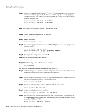
... memory Step 11 Exit the privileged level and return to dynamically setup SVCs. Router(config-if)# atm pvc 1 0 5 qsaal 3-18 Cisco 4000 Series Hardware Installation and Maintenance The example that the console terminal will be the source of protocol addresses to configure by entering the subcommand... follows is for the ATM unit 0: Router(config)# int atm 0 Step 3 Specify the framing type (for SONET interfaces, STS-3c is a switch in order to the user level: Router# disable The following example shows a basic configuration using using SVCs. Making Network Connections Step 5 Create the ...
... memory Step 11 Exit the privileged level and return to dynamically setup SVCs. Router(config-if)# atm pvc 1 0 5 qsaal 3-18 Cisco 4000 Series Hardware Installation and Maintenance The example that the console terminal will be the source of protocol addresses to configure by entering the subcommand... follows is for the ATM unit 0: Router(config)# int atm 0 Step 3 Specify the framing type (for SONET interfaces, STS-3c is a switch in order to the user level: Router# disable The following example shows a basic configuration using using SVCs. Making Network Connections Step 5 Create the ...
Hardware Maintenance Manual
Page 77
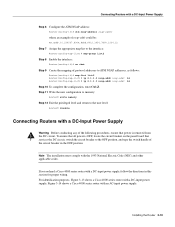
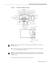
To ensure that all power is OFF, locate the circuit breaker on the panel board that services the DC circuit, switch the circuit breaker to the user level: Router# disable Connecting Routers with a DC-Input Power Supply Warning Before conducting any of the following procedures, ...directions in the OFF position. If you ordered a Cisco 4000 series router with a DC-input power supply; Step 11 Write the new configuration to memory: Router# write memory Step 12 Exit the privileged level and return to the OFF position, and tape the switch handle of protocol addresses to ATM NSAP addresses...
To ensure that all power is OFF, locate the circuit breaker on the panel board that services the DC circuit, switch the circuit breaker to the user level: Router# disable Connecting Routers with a DC-Input Power Supply Warning Before conducting any of the following procedures, ...directions in the OFF position. If you ordered a Cisco 4000 series router with a DC-input power supply; Step 11 Write the new configuration to memory: Router# write memory Step 12 Exit the privileged level and return to the OFF position, and tape the switch handle of protocol addresses to ATM NSAP addresses...
Hardware Maintenance Manual
Page 79
... Router 3-21 Caution To avoid damaging the power supply when returning the chassis to ensure user safety. Step 4 Remove the tape from the circuit breaker switch handle and restore power by moving the circuit breaker handle to the ON position.
... Router 3-21 Caution To avoid damaging the power supply when returning the chassis to ensure user safety. Step 4 Remove the tape from the circuit breaker switch handle and restore power by moving the circuit breaker handle to the ON position.

Hardware Maintenance Manual
Page 80
... source that the OK light located on software commands, refer to the appropriate software publications. 3-22 Cisco 4000 Series Hardware Installation and Maintenance For routers with the configuration command. Step 2 Turn ON the system power switch. Your configuration can be designated with either the setup command facility or with DC power input...
... source that the OK light located on software commands, refer to the appropriate software publications. 3-22 Cisco 4000 Series Hardware Installation and Maintenance For routers with the configuration command. Step 2 Turn ON the system power switch. Your configuration can be designated with either the setup command facility or with DC power input...
Hardware Maintenance Manual
Page 82
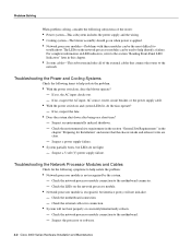
... Indicators" later in the chapter "Preparing for connection. • System will not initialize. - Suspect the processor or software. 4-2 Cisco 4000 Series Hardware Installation and Maintenance For complete information on LED indicators, refer to help isolate the problem: • Network processor module.... If no , suspect the AC input, AC source, router circuit breaker, or the power supply cable. • With the power switch on , does the blower operate? - Suspect an environmentally induced shutdown. - Check the environmental site requirements in the section "General Site ...
... Indicators" later in the chapter "Preparing for connection. • System will not initialize. - Suspect the processor or software. 4-2 Cisco 4000 Series Hardware Installation and Maintenance For complete information on LED indicators, refer to help isolate the problem: • Network processor module.... If no , suspect the AC input, AC source, router circuit breaker, or the power supply cable. • With the power switch on , does the blower operate? - Suspect an environmentally induced shutdown. - Check the environmental site requirements in the section "General Site ...
Hardware Maintenance Manual
Page 85
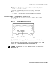
... 4-5 Reading Network Processor Module LED Indicators • POL (polarity)-When lit, this indicates the autopolarity reading detected the polarity was defective and corrected for it (switched it). • LNK (link)-When lit, this indicates 10BaseT is selected, and the link is available. • RX (receive)-When lit, this indicates the system...
... 4-5 Reading Network Processor Module LED Indicators • POL (polarity)-When lit, this indicates the autopolarity reading detected the polarity was defective and corrected for it (switched it). • LNK (link)-When lit, this indicates 10BaseT is selected, and the link is available. • RX (receive)-When lit, this indicates the system...
Hardware Maintenance Manual
Page 90
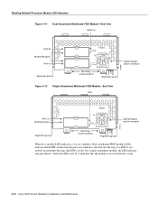
...ports PHY-A Alignment groove PHY-B PHY-A PHY-B RING OP FDDI OPT-BYPASS PHY-A RING OP Optical bypass switch connector H1400a Mounting screw locations Alignment groove Figure 4-12 Single-Attachment Multimode FDDI Module-End View LED PHY-S ...Multimode port Alignment groove PHY-S FDDI OPT-BYPASS PHY-S RING OPT Optical bypass switch connector H1401a Mounting screw locations Alignment groove When lit, a module LED indicates a ring up when lit;... if a PHY is not actively inserted into a ring. 4-10 Cisco 4000 Series Hardware Installation and Maintenance
...ports PHY-A Alignment groove PHY-B PHY-A PHY-B RING OP FDDI OPT-BYPASS PHY-A RING OP Optical bypass switch connector H1400a Mounting screw locations Alignment groove Figure 4-12 Single-Attachment Multimode FDDI Module-End View LED PHY-S ...Multimode port Alignment groove PHY-S FDDI OPT-BYPASS PHY-S RING OPT Optical bypass switch connector H1401a Mounting screw locations Alignment groove When lit, a module LED indicates a ring up when lit;... if a PHY is not actively inserted into a ring. 4-10 Cisco 4000 Series Hardware Installation and Maintenance
Hardware Maintenance Manual
Page 118
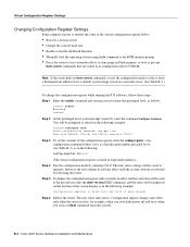
B-2 Cisco 4000 Series Hardware Installation and Maintenance end with DELETE, CTRL/W, and CTRL/U; The new value takes effect. however, the new settings do not take effect only when the server restarts, for example, when you switch the power off and on or when you issue a reload command from which to boot a default system...
B-2 Cisco 4000 Series Hardware Installation and Maintenance end with DELETE, CTRL/W, and CTRL/U; The new value takes effect. however, the new settings do not take effect only when the server restarts, for example, when you switch the power off and on or when you issue a reload command from which to boot a default system...

Hardware Maintenance Manual
Page 138
...media-type 2-10, 4-4 meminfo D-4 o (display virtual configuration register) C-3 o/r (reset) C-3 reload B-2 reset D-3 ROM monitor diagnostics Cisco 4000-M C-1 Cisco 4500-M D-1 Cisco 4700 D-1 setup 3-22 show version B-2 stack D-4 sysret D-4 t (test) C-3 terminal padding 3-2 component tray layout 5-5 config-register ...Cisco 4700 D-4 displaying settings C-3 resetting C-3 confreg command D-4 connections 10BaseT 2-10 9-pin D-type 3-2 auxiliary port 2-9 considerations when making 2-10 console port 2-9 Ethernet attaching to network 3-3 port, considerations 2-12 final 3-22 NT1 3-6 optical bypass switch...
...media-type 2-10, 4-4 meminfo D-4 o (display virtual configuration register) C-3 o/r (reset) C-3 reload B-2 reset D-3 ROM monitor diagnostics Cisco 4000-M C-1 Cisco 4500-M D-1 Cisco 4700 D-1 setup 3-22 show version B-2 stack D-4 sysret D-4 t (test) C-3 terminal padding 3-2 component tray layout 5-5 config-register ...Cisco 4700 D-4 displaying settings C-3 resetting C-3 confreg command D-4 connections 10BaseT 2-10 9-pin D-type 3-2 auxiliary port 2-9 considerations when making 2-10 console port 2-9 Ethernet attaching to network 3-3 port, considerations 2-12 final 3-22 NT1 3-6 optical bypass switch...
