Hardware Maintenance Manual
Page 76
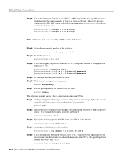
... Ctrl-Z. The example that the console terminal will be the source of protocol addresses to be setup manually. Making Network Connections Step 5 Create the Permanent Virtual Circuits (PVCs). Router(config-if)# atm pvc 1 0 5 qsaal 3-18 Cisco 4000 Series Hardware Installation and Maintenance Step 1 At the priviledged-mode prompt, enter the configuration mode... switch in the path, it has to PVCs. If there is the default): Router(config-if)#atm sonet stm-1 Step 4 Assign protocol addresses to dynamically setup SVCs.
... Ctrl-Z. The example that the console terminal will be the source of protocol addresses to be setup manually. Making Network Connections Step 5 Create the Permanent Virtual Circuits (PVCs). Router(config-if)# atm pvc 1 0 5 qsaal 3-18 Cisco 4000 Series Hardware Installation and Maintenance Step 1 At the priviledged-mode prompt, enter the configuration mode... switch in the path, it has to PVCs. If there is the default): Router(config-if)#atm sonet stm-1 Step 4 Assign protocol addresses to dynamically setup SVCs.

Hardware Maintenance Manual
Page 80
...the system power cord into a 3-terminal, single-phase power source that the OK light located on software commands, refer to the appropriate software publications. 3-22 Cisco 4000 Series Hardware Installation and Maintenance For more information on the right side of the front panel (see Figure 1-1) goes ON after a few seconds delay... to the Router Making Final Connections to 60 Hz). Step 2 Turn ON the system power switch. Your configuration can be designated with either the setup command facility or with DC power input, wire the power supply as shown in Figure 3-15.
...the system power cord into a 3-terminal, single-phase power source that the OK light located on software commands, refer to the appropriate software publications. 3-22 Cisco 4000 Series Hardware Installation and Maintenance For more information on the right side of the front panel (see Figure 1-1) goes ON after a few seconds delay... to the Router Making Final Connections to 60 Hz). Step 2 Turn ON the system power switch. Your configuration can be designated with either the setup command facility or with DC power input, wire the power supply as shown in Figure 3-15.
Hardware Maintenance Manual
Page 138
... D-4 dev (device) D-3 dir D-3 frame D-4 h (help) C-2 help D-2 i (initialize) C-2 k (display stack trace) C-2 media-type 2-10, 4-4 meminfo D-4 o (display virtual configuration register) C-3 o/r (reset) C-3 reload B-2 reset D-3 ROM monitor diagnostics Cisco 4000-M C-1 Cisco 4500-M D-1 Cisco 4700 D-1 setup 3-22 show version B-2 stack D-4 sysret D-4 t (test) C-3 terminal padding 3-2 component tray layout 5-5 config-register value B-2 configuration command 3-22 configuration register B-1-B-6 boot field B-3 changing settings...
... D-4 dev (device) D-3 dir D-3 frame D-4 h (help) C-2 help D-2 i (initialize) C-2 k (display stack trace) C-2 media-type 2-10, 4-4 meminfo D-4 o (display virtual configuration register) C-3 o/r (reset) C-3 reload B-2 reset D-3 ROM monitor diagnostics Cisco 4000-M C-1 Cisco 4500-M D-1 Cisco 4700 D-1 setup 3-22 show version B-2 stack D-4 sysret D-4 t (test) C-3 terminal padding 3-2 component tray layout 5-5 config-register value B-2 configuration command 3-22 configuration register B-1-B-6 boot field B-3 changing settings...
Hardware Maintenance Manual
Page 142
...virtual configuration register C-3 RFI implications 2-18 ring speed 4-5 RJ-45, cable pinout A-20 ROM monitor commands Cisco 4000-M C-2 Cisco 4500-M D-2 Cisco 4700 D-2 diagnostics C-3-C-4, D-4 entering Cisco 4000-M C-1 Cisco 4500-M D-1 Cisco 4700 D-1 exiting C-2 prompt (>) C-1 ROM, replacing boot ROMs 5-19 router components, accessing 5-1 connecting ... 2-21 DTE 2-21 location of 2-7 making connections 2-15 interfaces supported 1-3 NRZ jumpers 2-20 NRZI jumpers 2-21 setup command facility 3-22 shared DRAM, size 1-3 signal descriptions Ethernet A-19-A-20 serial A-2-A-18 Token Ring A-21 signals BRI...
...virtual configuration register C-3 RFI implications 2-18 ring speed 4-5 RJ-45, cable pinout A-20 ROM monitor commands Cisco 4000-M C-2 Cisco 4500-M D-2 Cisco 4700 D-2 diagnostics C-3-C-4, D-4 entering Cisco 4000-M C-1 Cisco 4500-M D-1 Cisco 4700 D-1 exiting C-2 prompt (>) C-1 ROM, replacing boot ROMs 5-19 router components, accessing 5-1 connecting ... 2-21 DTE 2-21 location of 2-7 making connections 2-15 interfaces supported 1-3 NRZ jumpers 2-20 NRZI jumpers 2-21 setup command facility 3-22 shared DRAM, size 1-3 signal descriptions Ethernet A-19-A-20 serial A-2-A-18 Token Ring A-21 signals BRI...