
Hardware Installation Guide
Page 9
... Switch and Running POST 3-10 Powering Off the Switch and Disconnecting the Console Port 3-11 Planning the Stack 3-12 Planning Considerations 3-12 Powering Considerations 3-13 Cabling Considerations 3-14 Recommended Cabling Configurations 3-15 Installing the Switch 3-17 Rack Mounting 3-18 Removing Screws from the Switch 3-19 Attaching... Catalyst 3750-24TS, 3750G-24T, 3750G-12S, and 3750-48TS Switches 3-25 Mounting the Switch in a Rack 3-28 Attaching the Cable Guide 3-30 Wall Mounting 3-32 Attaching the Brackets to the Switch for Wall-Mounting 3-32 Attaching the RPS Connector Cover 3-33 Mounting...
... Switch and Running POST 3-10 Powering Off the Switch and Disconnecting the Console Port 3-11 Planning the Stack 3-12 Planning Considerations 3-12 Powering Considerations 3-13 Cabling Considerations 3-14 Recommended Cabling Configurations 3-15 Installing the Switch 3-17 Rack Mounting 3-18 Removing Screws from the Switch 3-19 Attaching... Catalyst 3750-24TS, 3750G-24T, 3750G-12S, and 3750-48TS Switches 3-25 Mounting the Switch in a Rack 3-28 Attaching the Cable Guide 3-30 Wall Mounting 3-32 Attaching the Brackets to the Switch for Wall-Mounting 3-32 Attaching the RPS Connector Cover 3-33 Mounting...

Hardware Installation Guide
Page 10
... to 1000BASE-T SFP Modules 3-48 Where to Go Next 3-50 4 C H A P T E R Troubleshooting 4-1 Understanding POST Results 4-1 Clearing the Switch IP Address and Configuration 4-2 Diagnosing Problems 4-3 Replacing a Failed Stack Member 4-7 A A P P E N D I X Technical Specifications A-1 B A P P E N D I X Connector and Cable Specifications B-1 Connector Specifications B-1 10/100/1000 Ports B-1 Connecting to 1000BASE-T Devices B-2 10/100 Ports B-3 SFP Module Ports B-5 Console Port...
... to 1000BASE-T SFP Modules 3-48 Where to Go Next 3-50 4 C H A P T E R Troubleshooting 4-1 Understanding POST Results 4-1 Clearing the Switch IP Address and Configuration 4-2 Diagnosing Problems 4-3 Replacing a Failed Stack Member 4-7 A A P P E N D I X Technical Specifications A-1 B A P P E N D I X Connector and Cable Specifications B-1 Connector Specifications B-1 10/100/1000 Ports B-1 Connecting to 1000BASE-T Devices B-2 10/100 Ports B-3 SFP Module Ports B-5 Console Port...

Hardware Installation Guide
Page 11
Contents C A P P E N D I X D A P P E N D I X Crossover Cable and Adapter Pinouts B-9 Identifying a Crossover Cable B-9 Adapter Pinouts B-10 Managing the Switch by Using the Cluster Management Suite C-1 Connecting to an Ethernet Port C-2 Launching the Switch... CLI D-2 Accessing the CLI Through Express Setup (Unconfigured Switch Only) D-2 Accessing the CLI Through the Console Port D-3 Taking Out What You Need D-4 Stacking the Switches (Optional) D-5 Connecting to the Console Port D-7 Starting the Terminal Emulation Software D-9 Connecting to a Power Source D-9 Entering the Initial Configuration ...
Contents C A P P E N D I X D A P P E N D I X Crossover Cable and Adapter Pinouts B-9 Identifying a Crossover Cable B-9 Adapter Pinouts B-10 Managing the Switch by Using the Cluster Management Suite C-1 Connecting to an Ethernet Port C-2 Launching the Switch... CLI D-2 Accessing the CLI Through Express Setup (Unconfigured Switch Only) D-2 Accessing the CLI Through the Console Port D-3 Taking Out What You Need D-4 Stacking the Switches (Optional) D-5 Connecting to the Console Port D-7 Starting the Terminal Emulation Software D-9 Connecting to a Power Source D-9 Entering the Initial Configuration ...

Hardware Installation Guide
Page 12
... A P P E N D I X INDEX Translated Safety Warnings E-1 Attaching the Cisco RPS (model PWR300-AC-RPS-N1) E-1 Attaching the Cisco RPS (model PWR675-AC-RPS-N1) E-2 Installation Warning E-4 Installation Instructions E-5 Jewelry Removal Warning E-6 Stacking the Chassis Warning E-8 Main Disconnecting Device E-10 Grounded Equipment Warning E-11 Installing or ... E-19 Redundant Power Supply Connection Warning E-24 Switch Installation Warning E-25 Restricted Area E-27 Ethernet Cable Shielding in Offices E-28 Laser Beam Exposure E-30 Laser Radiation E-31 E-32 Catalyst 3750 Switch Hardware Installation Guide x 78...
... A P P E N D I X INDEX Translated Safety Warnings E-1 Attaching the Cisco RPS (model PWR300-AC-RPS-N1) E-1 Attaching the Cisco RPS (model PWR675-AC-RPS-N1) E-2 Installation Warning E-4 Installation Instructions E-5 Jewelry Removal Warning E-6 Stacking the Chassis Warning E-8 Main Disconnecting Device E-10 Grounded Equipment Warning E-11 Installing or ... E-19 Redundant Power Supply Connection Warning E-24 Switch Installation Warning E-25 Restricted Area E-27 Ethernet Cable Shielding in Offices E-28 Laser Beam Exposure E-30 Laser Radiation E-31 E-32 Catalyst 3750 Switch Hardware Installation Guide x 78...
Hardware Installation Guide
Page 30
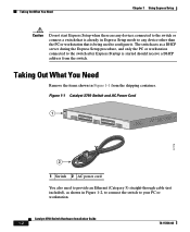
... is started should receive a DHCP address from the shipping container. Figure 1-1 Catalyst 3750 Switch and AC Power Cord 1 SYST RPS MASTR STAT 1X DUPLX SPEED STACK MODE 2X 11X 13X 12X 14X 23X Catalyst 3750 SERIES 24X 97175 2 1 Switch 2 AC power cord You also need to provide an Ethernet (Category 5) straight...
... is started should receive a DHCP address from the shipping container. Figure 1-1 Catalyst 3750 Switch and AC Power Cord 1 SYST RPS MASTR STAT 1X DUPLX SPEED STACK MODE 2X 11X 13X 12X 14X 23X Catalyst 3750 SERIES 24X 97175 2 1 Switch 2 AC power cord You also need to provide an Ethernet (Category 5) straight...

Hardware Installation Guide
Page 31
Figure 1-3 Connecting the Power 1 STACK 1 STACK 2 CONSOLE 1.2A-100R>06A-A2T4,IN05GV0-~60 HZ DSCPIENPCPO+IUWF1T2IEESvDRFISO@NUR1MP3RPAAELNYMUOATLE 97176 1 Switch 2 2 AC power cord 78-15136-02 Catalyst 3750 Switch Hardware Installation Guide 1-3 Chapter 1 Using Express Setup Figure 1-2 Ethernet Cable Powering On the Switch 89887 Powering On the Switch Complete these steps to power on the switch: Step 1 Connect one end of the AC power cord to the power connector on the switch rear panel, as shown in Figure 1-3.
Figure 1-3 Connecting the Power 1 STACK 1 STACK 2 CONSOLE 1.2A-100R>06A-A2T4,IN05GV0-~60 HZ DSCPIENPCPO+IUWF1T2IEESvDRFISO@NUR1MP3RPAAELNYMUOATLE 97176 1 Switch 2 2 AC power cord 78-15136-02 Catalyst 3750 Switch Hardware Installation Guide 1-3 Chapter 1 Using Express Setup Figure 1-2 Ethernet Cable Powering On the Switch 89887 Powering On the Switch Complete these steps to power on the switch: Step 1 Connect one end of the AC power cord to the power connector on the switch rear panel, as shown in Figure 1-3.

Hardware Installation Guide
Page 32
If the POST fails, see the "Understanding POST Results" section on a stack master switch. Starting Express Setup Express Setup is started should receive a DHCP address from the switch. The switch acts as a DHCP server during the Express ... POST is also green on a single switch or on page 4-2. You assign the IP information so that run automatically to determine a course of the power cable to the switch. Caution Do not start Express Setup until POST has completed. For information about troubleshooting a POST failure, see Chapter 4, "Troubleshooting," to ensure that...
If the POST fails, see the "Understanding POST Results" section on a stack master switch. Starting Express Setup Express Setup is started should receive a DHCP address from the switch. The switch acts as a DHCP server during the Express ... POST is also green on a single switch or on page 4-2. You assign the IP information so that run automatically to determine a course of the power cable to the switch. Caution Do not start Express Setup until POST has completed. For information about troubleshooting a POST failure, see Chapter 4, "Troubleshooting," to ensure that...

Hardware Installation Guide
Page 33
... the four LEDs above the Mode button turn green. Figure 1-4 Starting Express Setup SYST RPS MASTR STAT DUPLX SPEED STACK MODE 97173 1 1 Mode button Step 3 Release the Mode button. Step 4 Connect the Ethernet cable (not included) to a 10/100 Ethernet port or small form-factor pluggable (SFP) module port on page 4-2. Note...
... the four LEDs above the Mode button turn green. Figure 1-4 Starting Express Setup SYST RPS MASTR STAT DUPLX SPEED STACK MODE 97173 1 1 Mode button Step 3 Release the Mode button. Step 4 Connect the Ethernet cable (not included) to a 10/100 Ethernet port or small form-factor pluggable (SFP) module port on page 4-2. Note...

Hardware Installation Guide
Page 34
... Enter. Figure 1-5 Connecting the Switch and PC or Workstation Ethernet Ports 1 SYST RPS MASTR STAT 1X DUPLX SPEED STACK MODE 2X 11X 13X 12X 14X 23X Catalyst 3750 SERIES 24X 2 97174 3 1 Switch 2 Ethernet cable 3 PC or workstation Step 5 Step 6 Step 7 Connect the other than the PC or workstation being used to the... Installation Guide 1-6 78-15136-02 Starting Express Setup Chapter 1 Using Express Setup Caution Do not connect the switch to any device other end of the cable to configure it. Verify that the port status LEDs on your PC or workstation.
... Enter. Figure 1-5 Connecting the Switch and PC or Workstation Ethernet Ports 1 SYST RPS MASTR STAT 1X DUPLX SPEED STACK MODE 2X 11X 13X 12X 14X 23X Catalyst 3750 SERIES 24X 2 97174 3 1 Switch 2 Ethernet cable 3 PC or workstation Step 5 Step 6 Step 7 Connect the other than the PC or workstation being used to the... Installation Guide 1-6 78-15136-02 Starting Express Setup Chapter 1 Using Express Setup Caution Do not connect the switch to any device other end of the cable to configure it. Verify that the port status LEDs on your PC or workstation.

Hardware Installation Guide
Page 42
...100/1000 ports, autonegotiates the speed and supports only full-duplex mode • The Catalyst 3750 switches support stacking. Catalyst 3750G-12S-12 SFP module slots • The switches support these SFP modules: - 1000BASE-SX ...3750G-12S switches. Catalyst 3750G-24T-24 10/100/1000 Ethernet ports - Connection for optional Cisco RPS 300 redundant power system that operates on AC input and supplies backup DC power output ...1000 Mbps in full-duplex mode or in a stack by cabling the StackWise ports. Features Chapter 2 Product Overview Figure 2-1 through Figure 2-5 show the Catalyst 3750...
...100/1000 ports, autonegotiates the speed and supports only full-duplex mode • The Catalyst 3750 switches support stacking. Catalyst 3750G-12S-12 SFP module slots • The switches support these SFP modules: - 1000BASE-SX ...3750G-12S switches. Catalyst 3750G-24T-24 10/100/1000 Ethernet ports - Connection for optional Cisco RPS 300 redundant power system that operates on AC input and supplies backup DC power output ...1000 Mbps in full-duplex mode or in a stack by cabling the StackWise ports. Features Chapter 2 Product Overview Figure 2-1 through Figure 2-5 show the Catalyst 3750...

Hardware Installation Guide
Page 55
... 5 RPS connector StackWise Ports The Catalyst 3750 switch ships with a 0.5-meter StackWise cable (72-2632-XX CABASY) that you can order these StackWise cables from your Cisco sales representative: • CAB-STACK-50CM= (0.5-meter cable) • CAB-STACK-1M= (1-meter cable) • CAB-STACK-3M= (3-meter cable) 78-15136-02 Catalyst 3750 Switch Hardware Installation Guide 2-15 Caution Use...
... 5 RPS connector StackWise Ports The Catalyst 3750 switch ships with a 0.5-meter StackWise cable (72-2632-XX CABASY) that you can order these StackWise cables from your Cisco sales representative: • CAB-STACK-50CM= (0.5-meter cable) • CAB-STACK-1M= (1-meter cable) • CAB-STACK-3M= (3-meter cable) 78-15136-02 Catalyst 3750 Switch Hardware Installation Guide 2-15 Caution Use...

Hardware Installation Guide
Page 61
... to keep in this order: • Preparing for Installation, page 3-1 • Verifying Switch Operation, page 3-8 • Planning the Stack, page 3-12 • Installing the Switch, page 3-17 • Connecting StackWise Cable to StackWise Ports, page 3-37 • Connecting to the 10/100 and 10/100/1000 Ports, page 3-44 • Connecting to...
... to keep in this order: • Preparing for Installation, page 3-1 • Verifying Switch Operation, page 3-8 • Planning the Stack, page 3-12 • Installing the Switch, page 3-17 • Connecting StackWise Cable to StackWise Ports, page 3-37 • Connecting to the 10/100 and 10/100/1000 Ports, page 3-44 • Connecting to...
Hardware Installation Guide
Page 67
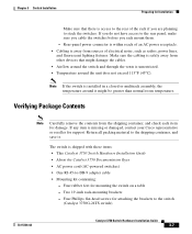
... is unrestricted. • Temperature around it . Return all packing material to the rear panel, make sure you cable the switches before you are planning to stack the switches. Note If the switch is installed in a closed or multirack assembly, the temperature around the unit...feet for damage. Verifying Package Contents Note Carefully remove the contents from sources of an AC power receptacle. • Cabling is missing or damaged, contact your Cisco representative or reseller for support. Two 19-inch rack-mounting brackets - Rear-panel power connector is within reach of electrical...
... is unrestricted. • Temperature around it . Return all packing material to the rear panel, make sure you cable the switches before you are planning to stack the switches. Note If the switch is installed in a closed or multirack assembly, the temperature around the unit...feet for damage. Verifying Package Contents Note Carefully remove the contents from sources of an AC power receptacle. • Cabling is missing or damaged, contact your Cisco representative or reseller for support. Two 19-inch rack-mounting brackets - Rear-panel power connector is within reach of electrical...

Hardware Installation Guide
Page 71
...3750G-12S, or 3750-48TS switches, you can use the Cisco RPS 300. Chapter 3 Switch Installation Preparing for Installation Step 3 Connect the other LEDs turn amber for 2 seconds. Disconnect the cable from the switch. The Speed and the Stack LEDs turn solid green, and each port LED turns off... . If there is a failure associated with a particular port, that the switch functions properly. Warning Attach only the Cisco RPS 300 (model PWR300-AC-...
...3750G-12S, or 3750-48TS switches, you can use the Cisco RPS 300. Chapter 3 Switch Installation Preparing for Installation Step 3 Connect the other LEDs turn amber for 2 seconds. Disconnect the cable from the switch. The Speed and the Stack LEDs turn solid green, and each port LED turns off... . If there is a failure associated with a particular port, that the switch functions properly. Warning Attach only the Cisco RPS 300 (model PWR300-AC-...

Hardware Installation Guide
Page 72
..., page 3-12 • Powering Considerations, page 3-13 • Cabling Considerations, page 3-14 • Recommended Cabling Configurations, page 3-15 Planning Considerations Before connecting the Catalyst 3750 switches in a stack, observe these planning considerations: • Size of the rack if you...stack your Cisco supplier. The "Recommended Cabling Configurations" section on page 3-15 provides examples of the StackWise cable, the 0.5-meter cable is access to the rear ports for unrestricted cabling. Depending on page 2-15. If you require the 1-meter cable or 3-meter cable...
..., page 3-12 • Powering Considerations, page 3-13 • Cabling Considerations, page 3-14 • Recommended Cabling Configurations, page 3-15 Planning Considerations Before connecting the Catalyst 3750 switches in a stack, observe these planning considerations: • Size of the rack if you...stack your Cisco supplier. The "Recommended Cabling Configurations" section on page 3-15 provides examples of the StackWise cable, the 0.5-meter cable is access to the rear ports for unrestricted cabling. Depending on page 2-15. If you require the 1-meter cable or 3-meter cable...

Hardware Installation Guide
Page 74
... 3-4 and Figure 3-5 show the stack bandwidth and possible stack partitioning. therefore, this stack provides only half bandwidth and does not have redundant connections. Planning the Stack Chapter 3 Switch Installation Cabling Considerations The illustrations in link B; therefore, this section display cabling configuration examples that provides full bandwidth and redundant StackWise cable connections. This stack provides only half bandwidth and...
... 3-4 and Figure 3-5 show the stack bandwidth and possible stack partitioning. therefore, this stack provides only half bandwidth and does not have redundant connections. Planning the Stack Chapter 3 Switch Installation Cabling Considerations The illustrations in link B; therefore, this section display cabling configuration examples that provides full bandwidth and redundant StackWise cable connections. This stack provides only half bandwidth and...

Hardware Installation Guide
Page 75
... Catalyst 3750 Switch Hardware Installation Guide 3-15 Stacking Switches in a vertical rack or on a Table Figure 3-6 is an example of a Partitioned Stack with a Failover Condition A B 86824 Recommended Cabling Configurations This section describes the recommended cabling configurations for stacking the switches. Chapter 3 Switch Installation Planning the Stack Figure 3-4 Example of a Stack with a Failover Condition 86822 A B C Figure 3-5 Example of...
... Catalyst 3750 Switch Hardware Installation Guide 3-15 Stacking Switches in a vertical rack or on a Table Figure 3-6 is an example of a Partitioned Stack with a Failover Condition A B 86824 Recommended Cabling Configurations This section describes the recommended cabling configurations for stacking the switches. Chapter 3 Switch Installation Planning the Stack Figure 3-4 Example of a Stack with a Failover Condition 86822 A B C Figure 3-5 Example of...

Hardware Installation Guide
Page 76
Figure 3-7 Stacking the Catalyst 3750 Switches in addition to the supplied 0.5-meter StackWise cable. This configuration also provides redundant connections. Planning the Stack Chapter 3 Switch Installation Figure 3-6 Stacking the Switches in a Vertical Rack or on a Table Using the 0.5-meter StackWise Cable 86586 The configuration examples in Figure 3-7 use the 3-meter StackWise cable in a Vertical Rack or on a Table Using 0.5-meter and 3-meter StackWise Cables 86585 3-16 Catalyst 3750 Switch Hardware Installation Guide 78-15136-02
Figure 3-7 Stacking the Catalyst 3750 Switches in addition to the supplied 0.5-meter StackWise cable. This configuration also provides redundant connections. Planning the Stack Chapter 3 Switch Installation Figure 3-6 Stacking the Switches in a Vertical Rack or on a Table Using the 0.5-meter StackWise Cable 86586 The configuration examples in Figure 3-7 use the 3-meter StackWise cable in a Vertical Rack or on a Table Using 0.5-meter and 3-meter StackWise Cables 86585 3-16 Catalyst 3750 Switch Hardware Installation Guide 78-15136-02

Hardware Installation Guide
Page 77
... Mounting, page 3-36 78-15136-02 Catalyst 3750 Switch Hardware Installation Guide 3-17 Figure 3-8 Stacking up to connect the switches. Use the 1-meter and 3-meter StackWise cables to Eight Switches in a Side-by-Side Mounting Configuration 86825 Figure 3-9 Stacking Nine Switches in a Rack or on a Wall Figure 3-8 and Figure 3-9 are examples of recommended...
... Mounting, page 3-36 78-15136-02 Catalyst 3750 Switch Hardware Installation Guide 3-17 Figure 3-8 Stacking up to connect the switches. Use the 1-meter and 3-meter StackWise cables to Eight Switches in a Side-by-Side Mounting Configuration 86825 Figure 3-9 Stacking Nine Switches in a Rack or on a Wall Figure 3-8 and Figure 3-9 are examples of recommended...

Hardware Installation Guide
Page 196
... Network Management Protocol See SNMP SNMP network management platforms 2-18 software switch management 2-18 specifications A-1 stacking cabling considerations 3-14 connecting to a StackWise port 3-12 examples 3-12 planning considerations 3-12 powering considerations 3-13 StackWise ports 2-15 straight-through cable pinout four twisted-pair 10/100 ports B-7 four twisted-pair 1000BASE-T ports B-8 two twisted-pair...
... Network Management Protocol See SNMP SNMP network management platforms 2-18 software switch management 2-18 specifications A-1 stacking cabling considerations 3-14 connecting to a StackWise port 3-12 examples 3-12 planning considerations 3-12 powering considerations 3-13 StackWise ports 2-15 straight-through cable pinout four twisted-pair 10/100 ports B-7 four twisted-pair 1000BASE-T ports B-8 two twisted-pair...