
Hardware Installation Guide
Page 8
...A P T E R 3 C H A P T E R Rerunning Express Setup 1-11 Where to Go Next 1-12 Other Switch Home Page Features 1-12 Installing or Connecting Devices to the Switch 1-12 Product Overview 2-1 Features 2-1 Front Panel Description 2-3 10/100 and 10/100/1000 Ports 2-6 SFP Module Slots 2-7 SFP... Connectors 2-16 Internal Power Supply Connector 2-16 Cisco RPS Connector 2-16 Console Port 2-17 Management Options 2-18 Network Configurations 2-19 Switch Installation 3-1 Preparing for Installation 3-1 Warnings 3-2 EMC Regulatory Statements 3-4 Catalyst 3750 Switch Hardware Installation Guide vi 78-15136-02
...A P T E R 3 C H A P T E R Rerunning Express Setup 1-11 Where to Go Next 1-12 Other Switch Home Page Features 1-12 Installing or Connecting Devices to the Switch 1-12 Product Overview 2-1 Features 2-1 Front Panel Description 2-3 10/100 and 10/100/1000 Ports 2-6 SFP Module Slots 2-7 SFP... Connectors 2-16 Internal Power Supply Connector 2-16 Cisco RPS Connector 2-16 Console Port 2-17 Management Options 2-18 Network Configurations 2-19 Switch Installation 3-1 Preparing for Installation 3-1 Warnings 3-2 EMC Regulatory Statements 3-4 Catalyst 3750 Switch Hardware Installation Guide vi 78-15136-02

Hardware Installation Guide
Page 9
... 3-13 Cabling Considerations 3-14 Recommended Cabling Configurations 3-15 Installing the Switch 3-17 Rack Mounting 3-18 Removing Screws from the Switch 3-19 Attaching Brackets to the Catalyst 3750G-24TS Switch 3-20 Attaching Brackets to the Catalyst 3750-24TS, 3750G-24T, 3750G-12S, and 3750-48TS Switches 3-25 Mounting the Switch in a Rack 3-28 Attaching the Cable Guide 3-30 Wall...
... 3-13 Cabling Considerations 3-14 Recommended Cabling Configurations 3-15 Installing the Switch 3-17 Rack Mounting 3-18 Removing Screws from the Switch 3-19 Attaching Brackets to the Catalyst 3750G-24TS Switch 3-20 Attaching Brackets to the Catalyst 3750-24TS, 3750G-24T, 3750G-12S, and 3750-48TS Switches 3-25 Mounting the Switch in a Rack 3-28 Attaching the Cable Guide 3-30 Wall...

Hardware Installation Guide
Page 12
... Unit E-12 Overtemperature Warning E-14 Working During Lightning Activity E-16 Product Disposal Warning E-17 Chassis Warning for Rack-Mounting and Servicing E-19 Redundant Power Supply Connection Warning E-24 Switch Installation Warning E-25 Restricted Area E-27 Ethernet Cable Shielding in Offices E-28 Laser Beam Exposure E-30 Laser Radiation E-31 E-32 Catalyst 3750 Switch Hardware Installation...
... Unit E-12 Overtemperature Warning E-14 Working During Lightning Activity E-16 Product Disposal Warning E-17 Chassis Warning for Rack-Mounting and Servicing E-19 Redundant Power Supply Connection Warning E-24 Switch Installation Warning E-25 Restricted Area E-27 Ethernet Cable Shielding in Offices E-28 Laser Beam Exposure E-30 Laser Radiation E-31 E-32 Catalyst 3750 Switch Hardware Installation...
Hardware Installation Guide
Page 17
... page. For information about the standard Cisco IOS Release 12.1 commands, refer to install a switch, and provides troubleshooting information. It describes the physical and performance characteristics of each switch, explains how to the IOS documentation set from the Cisco IOS Software drop-down list. 78-15136-02 Catalyst 3750 Switch Hardware Installation Guide xv We assume that...
... page. For information about the standard Cisco IOS Release 12.1 commands, refer to install a switch, and provides troubleshooting information. It describes the physical and performance characteristics of each switch, explains how to the IOS documentation set from the Cisco IOS Software drop-down list. 78-15136-02 Catalyst 3750 Switch Hardware Installation Guide xv We assume that...
Hardware Installation Guide
Page 29
...." For quick setup instructions for a standalone switch or a switch stack. If you are installing a new switch, refer to the Cisco IOS release label on switches running releases earlier than Cisco IOS Release 12.1(14)EA1, go to determine the release....switches running Cisco IOS Release 12.1(14)EA1 or later. The setup procedure includes these steps: • Taking Out What You Need, page 1-2 • Powering On the Switch, page 1-3 • Starting Express Setup, page 1-4 • Configuring the Switch Settings, page 1-9 • Where to Go Next, page 1-12 78-15136-02 Catalyst 3750 Switch...
...." For quick setup instructions for a standalone switch or a switch stack. If you are installing a new switch, refer to the Cisco IOS release label on switches running releases earlier than Cisco IOS Release 12.1(14)EA1, go to determine the release....switches running Cisco IOS Release 12.1(14)EA1 or later. The setup procedure includes these steps: • Taking Out What You Need, page 1-2 • Powering On the Switch, page 1-3 • Starting Express Setup, page 1-4 • Configuring the Switch Settings, page 1-9 • Where to Go Next, page 1-12 78-15136-02 Catalyst 3750 Switch...

Hardware Installation Guide
Page 36
...use either a crossover or a straight-through Ethernet cable between an Ethernet port of the switch and the Ethernet port of the PC or workstation, as shown Figure 1-5. Catalyst 3750 Switch Hardware Installation Guide 1-8 78-15136-02 If not, make sure that POST successfully ran ... switch software configuration guide or the switch command reference. To configure the switch by using the Express Setup web page. Starting Express Setup Chapter 1 Using Express Setup Re-enter 10.0.0.1 in the CLI to enable the automatic crossover feature. Note On switches running Cisco IOS Release 12...
...use either a crossover or a straight-through Ethernet cable between an Ethernet port of the switch and the Ethernet port of the PC or workstation, as shown Figure 1-5. Catalyst 3750 Switch Hardware Installation Guide 1-8 78-15136-02 If not, make sure that POST successfully ran ... switch software configuration guide or the switch command reference. To configure the switch by using the Express Setup web page. Starting Express Setup Chapter 1 Using Express Setup Re-enter 10.0.0.1 in the CLI to enable the automatic crossover feature. Note On switches running Cisco IOS Release 12...
Hardware Installation Guide
Page 38
Enter a password in Figure 1-8. 1-10 Catalyst 3750 Switch Hardware Installation Guide 78-15136-02 Enter the ...follow these steps to manage switches by using Cisco Works or another SNMP-based network-management system. Verifying Switch IP Address (Optional) After you have installed the switch in your settings. The switch exits Express Setup mode. If...Read Community field, the SNMP Write Community field, or both. Verifying Switch IP Address (Optional) Chapter 1 Using Express Setup Step 10 Step 11 Step 12 (Optional) Click Enable in the Telnet Access field if you are ...
Enter a password in Figure 1-8. 1-10 Catalyst 3750 Switch Hardware Installation Guide 78-15136-02 Enter the ...follow these steps to manage switches by using Cisco Works or another SNMP-based network-management system. Verifying Switch IP Address (Optional) After you have installed the switch in your settings. The switch exits Express Setup mode. If...Read Community field, the SNMP Write Community field, or both. Verifying Switch IP Address (Optional) Chapter 1 Using Express Setup Step 10 Step 11 Step 12 (Optional) Click Enable in the Telnet Access field if you are ...
Hardware Installation Guide
Page 40
... CMS requirements, see Chapter 3, "Installation." 1-12 Catalyst 3750 Switch Hardware Installation Guide 78-15136-02 Where to Go Next Chapter 1 Using Express Setup Where to Go Next After you have saved your switch on or under a desk or on a wall, or connecting devices to the switch, see Appendix C, "Managing the Switch by Using the Cluster Management...
... CMS requirements, see Chapter 3, "Installation." 1-12 Catalyst 3750 Switch Hardware Installation Guide 78-15136-02 Where to Go Next Chapter 1 Using Express Setup Where to Go Next After you have saved your switch on or under a desk or on a wall, or connecting devices to the switch, see Appendix C, "Managing the Switch by Using the Cluster Management...

Hardware Installation Guide
Page 42
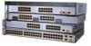
...a stack by cabling the StackWise ports. Catalyst 3750G-24T-24 10/100/1000 Ethernet ports - Connection for optional Cisco RPS 300 redundant power system that operates on AC input and supplies backup DC power output to nine switches in half-duplex mode at 10 or...8226; Configuration - Features Chapter 2 Product Overview Figure 2-1 through Figure 2-5 show the Catalyst 3750 switches. Catalyst 3750G-24TS-24 10/100/1000 Ethernet ports and 4 SFP module slots - Catalyst 3750G-12S-12 SFP module slots • The switches support these SFP modules: - 1000BASE-SX - 1000BASE-LX - 1000BASE-T Note When ...
...a stack by cabling the StackWise ports. Catalyst 3750G-24T-24 10/100/1000 Ethernet ports - Connection for optional Cisco RPS 300 redundant power system that operates on AC input and supplies backup DC power output to nine switches in half-duplex mode at 10 or...8226; Configuration - Features Chapter 2 Product Overview Figure 2-1 through Figure 2-5 show the Catalyst 3750 switches. Catalyst 3750G-24TS-24 10/100/1000 Ethernet ports and 4 SFP module slots - Catalyst 3750G-12S-12 SFP module slots • The switches support these SFP modules: - 1000BASE-SX - 1000BASE-LX - 1000BASE-T Note When ...

Hardware Installation Guide
Page 43
...In Figure 2-3 the SFP port are numbered 1 (left , as shown in pairs. Figure 2-1 Catalyst 3750-24TS Front Panel 86541 SYST RPS MASTR STAT DUPLX SPEED STACK MODE 12 1X 34 56 78 9 10 11 12 11X 2X 12X 13 14 13X 15 16 17 18 19 20 21 22 23 24...DC power output to 28. 78-15136-02 Catalyst 3750 Switch Hardware Installation Guide 2-3 Port 3 is above port 4, and so on . Chapter 2 Product Overview Front Panel Description Note The Cisco RPS 300 does not support the Catalyst 3750G-24TS switch. - Front Panel Description The Catalyst 3750-24TS 10/100 ports are grouped in Figure...
...In Figure 2-3 the SFP port are numbered 1 (left , as shown in pairs. Figure 2-1 Catalyst 3750-24TS Front Panel 86541 SYST RPS MASTR STAT DUPLX SPEED STACK MODE 12 1X 34 56 78 9 10 11 12 11X 2X 12X 13 14 13X 15 16 17 18 19 20 21 22 23 24...DC power output to 28. 78-15136-02 Catalyst 3750 Switch Hardware Installation Guide 2-3 Port 3 is above port 4, and so on . Chapter 2 Product Overview Front Panel Description Note The Cisco RPS 300 does not support the Catalyst 3750G-24TS switch. - Front Panel Description The Catalyst 3750-24TS 10/100 ports are grouped in Figure...

Hardware Installation Guide
Page 44
Catalyst 3750 Switch Hardware Installation Guide 2-4 78-15136-02 The ports are numbered 1 through 12. Front Panel Description Figure 2-2 Catalyst 3750G-24T Front Panel SYST RPS MASTR STAT DUPLX SPEED STACK MODE 12 1X 34 56 78 9 10 11 12 11X 2X 12X 13 14 13X 15 16 17 18 19 20 21 22 23 24 23X... 14X 24X 1 Catalyst 3750 SERIES 1 10/100/1000 ports Figure 2-3 Catalyst 3750G-24TS Front Panel Chapter 2 Product Overview 86543 86544 SYST RPS MASTR STAT DUPLX SPEED STACK MODE 12 1X 34 56 78 9 10 11 12 11X 2X 12X 13 14 13X 15 16 17 18...
Catalyst 3750 Switch Hardware Installation Guide 2-4 78-15136-02 The ports are numbered 1 through 12. Front Panel Description Figure 2-2 Catalyst 3750G-24T Front Panel SYST RPS MASTR STAT DUPLX SPEED STACK MODE 12 1X 34 56 78 9 10 11 12 11X 2X 12X 13 14 13X 15 16 17 18 19 20 21 22 23 24 23X... 14X 24X 1 Catalyst 3750 SERIES 1 10/100/1000 ports Figure 2-3 Catalyst 3750G-24TS Front Panel Chapter 2 Product Overview 86543 86544 SYST RPS MASTR STAT DUPLX SPEED STACK MODE 12 1X 34 56 78 9 10 11 12 11X 2X 12X 13 14 13X 15 16 17 18...

Hardware Installation Guide
Page 45
...35 36 37 38 39 40 41 42 43 44 45 46 47 48 47X 32X 34X 48X Catalyst 3750 SERIES 1 3 2 4 1 2 1 10/100 ports 2 SFP module ports 78-15136-02 Catalyst 3750 Switch Hardware Installation Guide 2-5 The SFP port numbers are grouped in Figure 2-1. The first member of the ...pair (port 1) is above the second member (port 2) on the far left, as shown in pairs. Chapter 2 Product Overview Figure 2-4 Catalyst 3750G-12S Front Panel Front Panel...
...35 36 37 38 39 40 41 42 43 44 45 46 47 48 47X 32X 34X 48X Catalyst 3750 SERIES 1 3 2 4 1 2 1 10/100 ports 2 SFP module ports 78-15136-02 Catalyst 3750 Switch Hardware Installation Guide 2-5 The SFP port numbers are grouped in Figure 2-1. The first member of the ...pair (port 1) is above the second member (port 2) on the far left, as shown in pairs. Chapter 2 Product Overview Figure 2-4 Catalyst 3750G-12S Front Panel Front Panel...

Hardware Installation Guide
Page 46
....3ab. (The default setting is a straight-through cable. When connecting the switch to the switch software configuration guide or the switch command reference. When the automatic crossover feature is disabled by default. Catalyst 3750 Switch Hardware Installation Guide 2-6 78-15136-02 In all cases, the attached device ... 100 Mbps, or 1000 Mbps in the CLI to use a crossover cable. Note On switches running Cisco IOS Release 12.1(14)EA1 or later, you can also set the 10/100/1000 ports to switches or hubs, use a twisted four-pair, Category 5 cable for 1000BASE-T connections, be ...
....3ab. (The default setting is a straight-through cable. When connecting the switch to the switch software configuration guide or the switch command reference. When the automatic crossover feature is disabled by default. Catalyst 3750 Switch Hardware Installation Guide 2-6 78-15136-02 In all cases, the attached device ... 100 Mbps, or 1000 Mbps in the CLI to use a crossover cable. Note On switches running Cisco IOS Release 12.1(14)EA1 or later, you can also set the 10/100/1000 ports to switches or hubs, use a twisted four-pair, Category 5 cable for 1000BASE-T connections, be ...

Hardware Installation Guide
Page 48
... Cluster Management Suite (CMS) home page. Figure 2-6 shows the Catalyst 3750-24TS, 3750G-24T, 3750G-24TS, 3750G-12S, and 3750-48TS LEDs and the Mode button that you use CMS to monitor switch activity and its performance. Figure 2-6 Catalyst 3750 LEDs SYST RPS MASTR STAT DUPLX SPEED STACK MODE 12345678... 9 12 1X 34 56 78 9 10 11 12 11X 2X 12X 1 Mode button 2 Stack LED 3 Speed LED 4 Duplex LED 5 Status...
... Cluster Management Suite (CMS) home page. Figure 2-6 shows the Catalyst 3750-24TS, 3750G-24T, 3750G-24TS, 3750G-12S, and 3750-48TS LEDs and the Mode button that you use CMS to monitor switch activity and its performance. Figure 2-6 Catalyst 3750 LEDs SYST RPS MASTR STAT DUPLX SPEED STACK MODE 12345678... 9 12 1X 34 56 78 9 10 11 12 11X 2X 12X 1 Mode button 2 Stack LED 3 Speed LED 4 Duplex LED 5 Status...
Hardware Installation Guide
Page 51
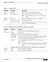
... 100, or 1000 Mbps. Table 2-5 Meaning of LED Colors in full-duplex mode. Port is operating in full duplex. 78-15136-02 Catalyst 3750 Switch Hardware Installation Guide 2-11 The port duplex mode: full duplex or half duplex. The StackWise port status. Green Link present. Flashing green Activity...transmitting or receiving data. Green Port is the default mode. Note The 10/100/1000 ports operate only in Different Modes on page 2-12 for a link-fault indication. Amber Port is blocked by STP and is not forwarding data. Alternating green-amber Link fault. Error ...
... 100, or 1000 Mbps. Table 2-5 Meaning of LED Colors in full-duplex mode. Port is operating in full duplex. 78-15136-02 Catalyst 3750 Switch Hardware Installation Guide 2-11 The port duplex mode: full duplex or half duplex. The StackWise port status. Green Link present. Flashing green Activity...transmitting or receiving data. Green Port is the default mode. Note The 10/100/1000 ports operate only in Different Modes on page 2-12 for a link-fault indication. Amber Port is blocked by STP and is not forwarding data. Alternating green-amber Link fault. Error ...

Hardware Installation Guide
Page 52
...number 8 of the stack. Note When installed in Catalyst 3750 switches, 1000BASE-T SFP modules can be members of a stack. The first nine port LEDs show the status for StackWise ports 1 and 2, respectively. 2-12 Catalyst 3750 Switch Hardware Installation Guide 78-15136-02 The other port ...LEDs are off because there are solid green, as these represent the member numbers of other stack member switches. Front Panel Description Chapter 2 Product Overview Table ...
...number 8 of the stack. Note When installed in Catalyst 3750 switches, 1000BASE-T SFP modules can be members of a stack. The first nine port LEDs show the status for StackWise ports 1 and 2, respectively. 2-12 Catalyst 3750 Switch Hardware Installation Guide 78-15136-02 The other port ...LEDs are off because there are solid green, as these represent the member numbers of other stack member switches. Front Panel Description Chapter 2 Product Overview Table ...

Hardware Installation Guide
Page 53
...46 45 46 47 48 47X Catalyst 3750 SERIES 1 2 3 48X 4 7 47 48 8 9 Catalyst 3750 SERIES 47X 1 2 3 48X 4 47 48 47X Catalyst 3750 SERIES 1 2 10 3 48X 4 11 12 13 1 2 3 86686 1 Stack member 8 2 Stack member 3 3 Stack member 4 78-15136-02 Catalyst 3750 Switch Hardware Installation Guide 2-13 Note If.... • The 10/100/1000 port LEDs 23 and 24 on the Catalyst 3750G-24T switch show the status for StackWise ports 1 and 2, respectively. If any of the port LEDs are green on the Catalyst 3750G-12S switch show the status for StackWise ports 1 and 2, respectively. • SFP...
...46 45 46 47 48 47X Catalyst 3750 SERIES 1 2 3 48X 4 7 47 48 8 9 Catalyst 3750 SERIES 47X 1 2 3 48X 4 47 48 47X Catalyst 3750 SERIES 1 2 10 3 48X 4 11 12 13 1 2 3 86686 1 Stack member 8 2 Stack member 3 3 Stack member 4 78-15136-02 Catalyst 3750 Switch Hardware Installation Guide 2-13 Note If.... • The 10/100/1000 port LEDs 23 and 24 on the Catalyst 3750G-24T switch show the status for StackWise ports 1 and 2, respectively. If any of the port LEDs are green on the Catalyst 3750G-12S switch show the status for StackWise ports 1 and 2, respectively. • SFP...

Hardware Installation Guide
Page 54
Rear Panel Description Chapter 2 Product Overview Rear Panel Description The switch rear panels have an AC power connector, an RPS connector, an RJ-45 console port, and two StackWise ports. (See Figure 2-8 and Figure 2-9.) Figure 2-8 Catalyst 3750-24TS, 3750G-24T, 3750G-12S, and 3750-48TS Rear Panel 86548 STACK 1 STACK 2 CONSOLE 1.6A-100R>09A...
Rear Panel Description Chapter 2 Product Overview Rear Panel Description The switch rear panels have an AC power connector, an RPS connector, an RJ-45 console port, and two StackWise ports. (See Figure 2-8 and Figure 2-9.) Figure 2-8 Catalyst 3750-24TS, 3750G-24T, 3750G-12S, and 3750-48TS Rear Panel 86548 STACK 1 STACK 2 CONSOLE 1.6A-100R>09A...

Hardware Installation Guide
Page 56
...Cisco RPS Connector Specific Cisco RPS modes support specific Catalyst 3750 switches: • Cisco RPS 300 (model PWR300-AC-RPS-N1) supports the Catalyst 3750-24TS, 3750G-24T, 3750G-12S, and 3750-48TS switches. • Cisco RPS 675 (model PWR675-AC-RPS-N1=) supports the Catalyst 3750 family of 300W. Rear Panel Description Chapter 2 Product Overview Power Connectors The switch... outlet. Note The Cisco RPS 300 does not support the Catalyst 3750G-24TS switches. Warning Attach only the Cisco RPS (model PWR300-AC-RPS-N1) to provide backup power if the switch internal power supply should...
...Cisco RPS Connector Specific Cisco RPS modes support specific Catalyst 3750 switches: • Cisco RPS 300 (model PWR300-AC-RPS-N1) supports the Catalyst 3750-24TS, 3750G-24T, 3750G-12S, and 3750-48TS switches. • Cisco RPS 675 (model PWR675-AC-RPS-N1=) supports the Catalyst 3750 family of 300W. Rear Panel Description Chapter 2 Product Overview Power Connectors The switch... outlet. Note The Cisco RPS 300 does not support the Catalyst 3750G-24TS switches. Warning Attach only the Cisco RPS (model PWR300-AC-RPS-N1) to provide backup power if the switch internal power supply should...

Hardware Installation Guide
Page 61
... to keep in this order: • Preparing for Installation, page 3-1 • Verifying Switch Operation, page 3-8 • Planning the Stack, page 3-12 • Installing the Switch, page 3-17 • Connecting StackWise Cable to StackWise Ports, page 3-37 • Connecting...switch and make connections to Go Next, page 3-50 Preparing for Installation This section covers these topics: • Warnings, page 3-2 • EMC Regulatory Statements, page 3-4 • Installation Guidelines, page 3-6 78-15136-02 Catalyst 3750 Switch Hardware Installation Guide 3-1 CH A P T E R 3 Switch...
... to keep in this order: • Preparing for Installation, page 3-1 • Verifying Switch Operation, page 3-8 • Planning the Stack, page 3-12 • Installing the Switch, page 3-17 • Connecting StackWise Cable to StackWise Ports, page 3-37 • Connecting...switch and make connections to Go Next, page 3-50 Preparing for Installation This section covers these topics: • Warnings, page 3-2 • EMC Regulatory Statements, page 3-4 • Installation Guidelines, page 3-6 78-15136-02 Catalyst 3750 Switch Hardware Installation Guide 3-1 CH A P T E R 3 Switch...

