
Installation Guide
Page 2
...protection against harmful interference when the equipment is an adaptation of a program developed by the Cisco equipment or one side or the other of California. These specifications are designed to operate the product. The following information is causing interference by turning it ...a residential installation. If it is for FCC compliance of the FCC rules. THE SPECIFICATIONS AND INFORMATION REGARDING THE PRODUCTS IN THIS MANUAL ARE SUBJECT TO CHANGE WITHOUT NOTICE. CISCO AND THE ABOVE-NAMED SUPPLIERS DISCLAIM ALL WARRANTIES, EXPRESSED OR IMPLIED, INCLUDING, WITHOUT ...
...protection against harmful interference when the equipment is an adaptation of a program developed by the Cisco equipment or one side or the other of California. These specifications are designed to operate the product. The following information is causing interference by turning it ...a residential installation. If it is for FCC compliance of the FCC rules. THE SPECIFICATIONS AND INFORMATION REGARDING THE PRODUCTS IN THIS MANUAL ARE SUBJECT TO CHANGE WITHOUT NOTICE. CISCO AND THE ABOVE-NAMED SUPPLIERS DISCLAIM ALL WARRANTIES, EXPRESSED OR IMPLIED, INCLUDING, WITHOUT ...

Installation Guide
Page 8
Contents A A P P E N D I X B A P P E N D I X C A P P E N D I X Technical Specifications A-1 Connector and Cable Specifications B-1 Connector Specifications B-1 10/100 Ports B-1 1000BaseX Ports B-2 Gigastack Port B-3 Console Port B-3 Cable and Adapter Specifications B-4 Crossover and Straight-Through Cable Pinouts B-4 Rollover Cable and Adapter Pinouts B-5 Identifying a Rollover Cable B-5 Connecting to a PC B-6 Connecting to a Terminal B-7 Translated Safety Warnings C-1 Attaching the Cisco RPS (model PWR600-AC-RPS) C-2 Attaching the Cisco RPS (model PWR300...
Contents A A P P E N D I X B A P P E N D I X C A P P E N D I X Technical Specifications A-1 Connector and Cable Specifications B-1 Connector Specifications B-1 10/100 Ports B-1 1000BaseX Ports B-2 Gigastack Port B-3 Console Port B-3 Cable and Adapter Specifications B-4 Crossover and Straight-Through Cable Pinouts B-4 Rollover Cable and Adapter Pinouts B-5 Identifying a Rollover Cable B-5 Connecting to a PC B-6 Connecting to a Terminal B-7 Translated Safety Warnings C-1 Attaching the Cisco RPS (model PWR600-AC-RPS) C-2 Attaching the Cisco RPS (model PWR300...

Installation Guide
Page 12
... resolve some of the warnings in this guide. Appendix A, "Technical Specifications," lists the physical and environmental specifications for installing a switch on a rack, wall, table, or shelf. Chapter 2, "Installing and Starting Up the Switch," contains the procedures for the switches and the regulatory agency approvals. Catalyst 3500 Series XL Hardware Installation Guide xii 78-6456-04 Examples...
... resolve some of the warnings in this guide. Appendix A, "Technical Specifications," lists the physical and environmental specifications for installing a switch on a rack, wall, table, or shelf. Chapter 2, "Installing and Starting Up the Switch," contains the procedures for the switches and the regulatory agency approvals. Catalyst 3500 Series XL Hardware Installation Guide xii 78-6456-04 Examples...

Installation Guide
Page 25
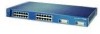
... switches. A feature specific to the Catalyst 3524-PWR XL switch is its ability to provide inline power to Cisco IP Phones. (Phone adapters are not required when connecting to the Catalyst 3524-PWR XL 10/100 switch ports.) Figure 1-1 shows the switch models in different network topologies Features The Catalyst 3500 series XL switches-also referred to as Catalyst 3500 XL switches-are stackable 10/100...
... switches. A feature specific to the Catalyst 3524-PWR XL switch is its ability to provide inline power to Cisco IP Phones. (Phone adapters are not required when connecting to the Catalyst 3524-PWR XL 10/100 switch ports.) Figure 1-1 shows the switch models in different network topologies Features The Catalyst 3500 series XL switches-also referred to as Catalyst 3500 XL switches-are stackable 10/100...

Installation Guide
Page 32
... can use a crossover cable. However, the Catalyst 3524-PWR XL 10/100 ports can sense the speed and duplex settings of half duplex, full duplex, 10 Mbps, or 100 Mbps. When connecting the switch to workstations, servers, routers, and Cisco IP Phones, be connected to operate in Appendix B, "Connector and Cable Specifications." When set to an AC power...
... can use a crossover cable. However, the Catalyst 3524-PWR XL 10/100 ports can sense the speed and duplex settings of half duplex, full duplex, 10 Mbps, or 100 Mbps. When connecting the switch to workstations, servers, routers, and Cisco IP Phones, be connected to operate in Appendix B, "Connector and Cable Specifications." When set to an AC power...

Installation Guide
Page 47
...for four external devices that supports input voltages between 100 and 240 VAC. The power source is not. The switches do not support the fully-redundant configuration described in the RPS documentation. The AC input to the Cisco RPS is fully redundant, but the DC output to... plan to use the internal power supply, use up to 150W DC each. Cisco RPS Connector Specific Cisco RPS models support specific Catalyst 3500 XL switches: • Cisco RPS 600 (model PWR600-AC-RPS)-Supports the Catalyst 3512, 3524, 3548, and 3508 XL switches • Cisco RPS 300 (model PWR300-AC-RPS)-Supports the...
...for four external devices that supports input voltages between 100 and 240 VAC. The power source is not. The switches do not support the fully-redundant configuration described in the RPS documentation. The AC input to the Cisco RPS is fully redundant, but the DC output to... plan to use the internal power supply, use up to 150W DC each. Cisco RPS Connector Specific Cisco RPS models support specific Catalyst 3500 XL switches: • Cisco RPS 600 (model PWR600-AC-RPS)-Supports the Catalyst 3512, 3524, 3548, and 3508 XL switches • Cisco RPS 300 (model PWR300-AC-RPS)-Supports the...

Installation Guide
Page 48
... a terminal. For console port and adapter pinout information, see the "Cable and Adapter Specifications" section on page B-4. Management Options Catalyst 3500 XL switches offer several management options: • Cisco Cluster Management Suite This suite is made up of the console port and the supplied rollover... Connector on the Catalyst 3524-PWR XL Switch The Cisco RPS 300 (model PWR300-AC-RPS) has two output levels: -48V and 12V with a total output power of switches or an individual switch. It provides a fully-redundant power source for these applications. 1-24 Catalyst 3500 Series XL ...
... a terminal. For console port and adapter pinout information, see the "Cable and Adapter Specifications" section on page B-4. Management Options Catalyst 3500 XL switches offer several management options: • Cisco Cluster Management Suite This suite is made up of the console port and the supplied rollover... Connector on the Catalyst 3524-PWR XL Switch The Cisco RPS 300 (model PWR300-AC-RPS) has two output levels: -48V and 12V with a total output power of switches or an individual switch. It provides a fully-redundant power source for these applications. 1-24 Catalyst 3500 Series XL ...

Installation Guide
Page 65
...: • For 10/100 ports, cable lengths from the switch to connected devices are up to 100 meters. • For 1000BaseX ports, cable lengths from the switch to the connected devices are up to the Hungarian EMC Class A requirements (MSZEN55022). For specific cable lengths, refer to...Warning This equipment is within the ranges listed in Appendix A, "Technical Specifications." 78-6456-04 Catalyst 3500 Series XL Hardware Installation Guide 2-7 Chapter 2 Installing and Starting Up the Switch Hungary Preparing for which special conditions of installation and protection distance are used...
...: • For 10/100 ports, cable lengths from the switch to connected devices are up to 100 meters. • For 1000BaseX ports, cable lengths from the switch to the connected devices are up to the Hungarian EMC Class A requirements (MSZEN55022). For specific cable lengths, refer to...Warning This equipment is within the ranges listed in Appendix A, "Technical Specifications." 78-6456-04 Catalyst 3500 Series XL Hardware Installation Guide 2-7 Chapter 2 Installing and Starting Up the Switch Hungary Preparing for which special conditions of installation and protection distance are used...

Installation Guide
Page 81
... the PC or terminal to the switch: Step 1 Step 2 Be sure that adapter from Cisco. See the Cisco IOS Desktop Switching Software Configuration Guide for instructions. 78-6456-04 Catalyst 3500 Series XL Hardware Installation Guide 2-23 For console port and adapter pinout information, see the "Cable and Adapter Specifications" section on the GigaStack GBIC connections...
... the PC or terminal to the switch: Step 1 Step 2 Be sure that adapter from Cisco. See the Cisco IOS Desktop Switching Software Configuration Guide for instructions. 78-6456-04 Catalyst 3500 Series XL Hardware Installation Guide 2-23 For console port and adapter pinout information, see the "Cable and Adapter Specifications" section on the GigaStack GBIC connections...

Installation Guide
Page 84
... press Return: 2-26 Catalyst 3500 Series XL Hardware Installation Guide 78-6456-04 You need to provide a RJ-45-to-DB-25 female DTE adapter if you like to restart the setup program. You can order a kit (part number ACS-DSBUASYN=) containing that adapter from Cisco. Step 1 Step 2 Step ... does not appear, enter enable, and press Return. For console port and adapter pinout information, see the "Cable and Adapter Specifications" section on page B-4. Enter the switch IP address, and press Return: Enter IP address: ip_address Enter the subnet mask (IP netmask) address, and press Return: ...
... press Return: 2-26 Catalyst 3500 Series XL Hardware Installation Guide 78-6456-04 You need to provide a RJ-45-to-DB-25 female DTE adapter if you like to restart the setup program. You can order a kit (part number ACS-DSBUASYN=) containing that adapter from Cisco. Step 1 Step 2 Step ... does not appear, enter enable, and press Return. For console port and adapter pinout information, see the "Cable and Adapter Specifications" section on page B-4. Enter the switch IP address, and press Return: Enter IP address: ip_address Enter the subnet mask (IP netmask) address, and press Return: ...

Installation Guide
Page 97
...specifications for the Catalyst 3508G XL Switch Environmental Ranges Operating temperature Storage temperature Operating humidity Operating altitude Storage altitude Power Requirements AC input voltage DC input voltages Power consumption Physical Dimensions Weight Dimensions (H x W x D) 32 to 113°F (0 to 45°C) -4 to 149°F (-10 to 65°C) 10 to 85% (noncondensing) Up to 10...,000 ft (3000 m) Up to 15,000 ft (4570 m) 100 to 127/200 to 240 VAC (autoranging) 50 to 60 Hz +3.3V @...
...specifications for the Catalyst 3508G XL Switch Environmental Ranges Operating temperature Storage temperature Operating humidity Operating altitude Storage altitude Power Requirements AC input voltage DC input voltages Power consumption Physical Dimensions Weight Dimensions (H x W x D) 32 to 113°F (0 to 45°C) -4 to 149°F (-10 to 65°C) 10 to 85% (noncondensing) Up to 10...,000 ft (3000 m) Up to 15,000 ft (4570 m) 100 to 127/200 to 240 VAC (autoranging) 50 to 60 Hz +3.3V @...

Installation Guide
Page 98
Appendix A Technical Specifications Table A-2 Technical Specifications for the Catalyst 3512, 3524, and 3548 XL Switches Catalyst 3512 XL Catalyst 3524 XL Catalyst 3548 XL Environmental Ranges Operating temperature 32 to 113°F (0 to 45°C) 32 to 113°F (0 to 45°C) 32 to 113°F (0 to 45°C) Storage temperature -4 to 149°F (-10 to 65°C) -4 to...
Appendix A Technical Specifications Table A-2 Technical Specifications for the Catalyst 3512, 3524, and 3548 XL Switches Catalyst 3512 XL Catalyst 3524 XL Catalyst 3548 XL Environmental Ranges Operating temperature 32 to 113°F (0 to 45°C) 32 to 113°F (0 to 45°C) 32 to 113°F (0 to 45°C) Storage temperature -4 to 149°F (-10 to 65°C) -4 to...

Installation Guide
Page 99
...24 IP phones connected. Appendix A Technical Specifications Table A-3 Technical Specifications for the Catalyst 3524-PWR XL Switch Environmental Ranges Operating temperature 32 to 113°F (0 to 45°C) Storage temperature -4 to 149°F (-10 to 65°C) Operating humidity 10 to 85% (noncondensing) Operating altitude Up to 10...voltage DC input voltages Power consumption 100 to 127/200 to 240 VAC (autoranging) 50 to NOM-019-SCFI CE Marking CE Marking 78-6456-04 Catalyst 3500 Series XL Hardware Installation Guide A-3 Table A-4 Catalyst 3500 Series XL Agency Approvals ...
...24 IP phones connected. Appendix A Technical Specifications Table A-3 Technical Specifications for the Catalyst 3524-PWR XL Switch Environmental Ranges Operating temperature 32 to 113°F (0 to 45°C) Storage temperature -4 to 149°F (-10 to 65°C) Operating humidity 10 to 85% (noncondensing) Operating altitude Up to 10...voltage DC input voltages Power consumption 100 to 127/200 to 240 VAC (autoranging) 50 to NOM-019-SCFI CE Marking CE Marking 78-6456-04 Catalyst 3500 Series XL Hardware Installation Guide A-3 Table A-4 Catalyst 3500 Series XL Agency Approvals ...

Installation Guide
Page 100
Appendix A Technical Specifications Catalyst 3500 Series XL Hardware Installation Guide A-4 78-6456-04
Appendix A Technical Specifications Catalyst 3500 Series XL Hardware Installation Guide A-4 78-6456-04

Installation Guide
Page 101
...). APPENDIX B Connector and Cable Specifications This appendix describes the Catalyst 3500 XL switch ports and the cables and adapters that you use to connect the switch to connect two ports when one of the ports is designated with an X. When connecting the 10/100 ports to compatible workstations, servers, routers, and Cisco IP Phones, you must use...
...). APPENDIX B Connector and Cable Specifications This appendix describes the Catalyst 3500 XL switch ports and the cables and adapters that you use to connect the switch to connect two ports when one of the ports is designated with an X. When connecting the 10/100 ports to compatible workstations, servers, routers, and Cisco IP Phones, you must use...

Installation Guide
Page 102
Figure B-2 1000BaseX SC Connector H8707 Tx Rx Catalyst 3500 Series XL Hardware Installation Guide B-2 78-6456-04 Connector Specifications Appendix B Connector and Cable Specifications Figure B-1 10/100 Port Pinouts Pin Label 1 RD+ 2 RD- 3 TD+ 4 NC 5 NC 6 TD- 7 NC 8 NC 12345678 H5318 1000BaseX Ports 1000BaseX ports use duplex SC connectors, as shown in Figure B-2.
Figure B-2 1000BaseX SC Connector H8707 Tx Rx Catalyst 3500 Series XL Hardware Installation Guide B-2 78-6456-04 Connector Specifications Appendix B Connector and Cable Specifications Figure B-1 10/100 Port Pinouts Pin Label 1 RD+ 2 RD- 3 TD+ 4 NC 5 NC 6 TD- 7 NC 8 NC 12345678 H5318 1000BaseX Ports 1000BaseX ports use duplex SC connectors, as shown in Figure B-2.

Installation Guide
Page 103
You can order a kit (part number ACS-DSBUASYN=) containing that adapter from Cisco. Console Port The console port uses an 8-pin RJ-45 connector, described in Figure B-3. The supplied RJ-45-to-RJ-45 rollover cable ... port of the switch to a terminal. For console port and adapter pinout information, see Table B-1 and Table B-2. 78-6456-04 Catalyst 3500 Series XL Hardware Installation Guide B-3 Caution Do not use standard IEEE 1394 cables with enhanced signal integrity and EMI performance. Appendix B Connector and Cable Specifications Connector Specifications Gigastack Port The ...
You can order a kit (part number ACS-DSBUASYN=) containing that adapter from Cisco. Console Port The console port uses an 8-pin RJ-45 connector, described in Figure B-3. The supplied RJ-45-to-RJ-45 rollover cable ... port of the switch to a terminal. For console port and adapter pinout information, see Table B-1 and Table B-2. 78-6456-04 Catalyst 3500 Series XL Hardware Installation Guide B-3 Caution Do not use standard IEEE 1394 cables with enhanced signal integrity and EMI performance. Appendix B Connector and Cable Specifications Connector Specifications Gigastack Port The ...

Installation Guide
Page 104
Cable and Adapter Specifications Appendix B Connector and Cable Specifications Cable and Adapter Specifications Crossover and Straight-Through Cable Pinouts The schematics of crossover and straight-through cables are shown in Figure B-4 and Figure B-5. Switch 3 TD+ 6 TD- 1 RD+ 2 RD- 1 RD+ 2 RD- Switch 3 RD+ 6 RD- 1 RD+ 2 RD- 1 TD+ 2 TD- H5579 Figure B-5 Straight-Through Cable Schematic Switch 3 TD+ 6 TD- H5578 Catalyst 3500 Series XL Hardware Installation Guide B-4 78-6456-04 Figure B-4 Crossover Cable Schematic Switch 3 TD+ 6 TD-
Cable and Adapter Specifications Appendix B Connector and Cable Specifications Cable and Adapter Specifications Crossover and Straight-Through Cable Pinouts The schematics of crossover and straight-through cables are shown in Figure B-4 and Figure B-5. Switch 3 TD+ 6 TD- 1 RD+ 2 RD- 1 RD+ 2 RD- Switch 3 RD+ 6 RD- 1 RD+ 2 RD- 1 TD+ 2 TD- H5579 Figure B-5 Straight-Through Cable Schematic Switch 3 TD+ 6 TD- H5578 Catalyst 3500 Series XL Hardware Installation Guide B-4 78-6456-04 Figure B-4 Crossover Cable Schematic Switch 3 TD+ 6 TD-

Installation Guide
Page 105
Appendix B Connector and Cable Specifications Cable and Adapter Specifications Rollover Cable and Adapter Pinouts Identifying a Rollover Cable To identify a rollover cable, compare the two modular ends of the right plug (see Figure B-6). Hold the cable ends side-by-side, with the tab at the back. Pin 8 H10632 78-6456-04 Catalyst 3500 Series XL...
Appendix B Connector and Cable Specifications Cable and Adapter Specifications Rollover Cable and Adapter Pinouts Identifying a Rollover Cable To identify a rollover cable, compare the two modular ends of the right plug (see Figure B-6). Hold the cable ends side-by-side, with the tab at the back. Pin 8 H10632 78-6456-04 Catalyst 3500 Series XL...

Installation Guide
Page 106
... 8 6 2 5 5 3 4 7 Console Device Signal CTS DSR RxD GND GND TxD DTR RTS Catalyst 3500 Series XL Hardware Installation Guide B-6 78-6456-04 Figure B-7 Connecting the Console Port to a PC PC Catalyst 3500 series XL switch 22003 RJ-45-to-RJ-45 rollover cable RJ-45-to-DB-9 adapter (labeled TERMINAL... female DTE adapter. Figure B-7 shows how to connect the console port to a PC running terminal-emulation software. Cable and Adapter Specifications Appendix B Connector and Cable Specifications Connecting to a PC Use the supplied thin, flat, RJ-45-to-RJ-45 rollover cable and RJ-45-to-DB-9 female ...
... 8 6 2 5 5 3 4 7 Console Device Signal CTS DSR RxD GND GND TxD DTR RTS Catalyst 3500 Series XL Hardware Installation Guide B-6 78-6456-04 Figure B-7 Connecting the Console Port to a PC PC Catalyst 3500 series XL switch 22003 RJ-45-to-RJ-45 rollover cable RJ-45-to-DB-9 adapter (labeled TERMINAL... female DTE adapter. Figure B-7 shows how to connect the console port to a PC running terminal-emulation software. Cable and Adapter Specifications Appendix B Connector and Cable Specifications Connecting to a PC Use the supplied thin, flat, RJ-45-to-RJ-45 rollover cable and RJ-45-to-DB-9 female ...