Software Guide
Page 17
...E R 78-15486-01 Configuring a Login Banner 27-4 Clearing the Login Banner 27-5 Enabling or Disabling the "Cisco Systems Console" Telnet Login Banner 27-5 Defining and Using Command Aliases 27-6 Defining and Using IP Aliases 27-7 ...Switch to a Catalyst 4500 Series Switch 28-10 Understanding How Inline Power Works 28-11 Inline Power Management Modes 28-12 Power Requirements 28-12 Phone Detection Summary 28-14 Configuring Power Management 28-14 Setting Redundant Mode for the Catalyst 4500 Series Switches 28-14 Setting Combined Mode on the Catalyst 4500 Series Switches 28-15 Setting the DC...
...E R 78-15486-01 Configuring a Login Banner 27-4 Clearing the Login Banner 27-5 Enabling or Disabling the "Cisco Systems Console" Telnet Login Banner 27-5 Defining and Using Command Aliases 27-6 Defining and Using IP Aliases 27-7 ...Switch to a Catalyst 4500 Series Switch 28-10 Understanding How Inline Power Works 28-11 Inline Power Management Modes 28-12 Power Requirements 28-12 Phone Detection Summary 28-14 Configuring Power Management 28-14 Setting Redundant Mode for the Catalyst 4500 Series Switches 28-14 Setting Combined Mode on the Catalyst 4500 Series Switches 28-15 Setting the DC...

Software Guide
Page 411
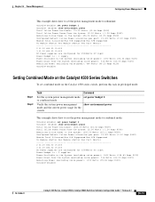
...Logout ok off ok 0,18:24:41 none PS1-Type PS2-Type PS3-Type WS-X4008-DC-650W WS-X4008 WS-X4008 Modem Baud Traffic Peak Peak-Time 78-15486-01 Catalyst 4500 Series, Catalyst 2948G, Catalyst 2980G Switches Software Configuration Guide-Release 8.1 27-3 Console> (enable) set system location Sunnyvale CA...show system This example shows how to set the system contact to [email protected] and location to set the system prompt for the switch: Console> (enable) set prompt Catalyst4012> Catalyst4012> (enable) Clearing the System Name To clear the system name, perform this task in...
...Logout ok off ok 0,18:24:41 none PS1-Type PS2-Type PS3-Type WS-X4008-DC-650W WS-X4008 WS-X4008 Modem Baud Traffic Peak Peak-Time 78-15486-01 Catalyst 4500 Series, Catalyst 2948G, Catalyst 2980G Switches Software Configuration Guide-Release 8.1 27-3 Console> (enable) set system location Sunnyvale CA...show system This example shows how to set the system contact to [email protected] and location to set the system prompt for the switch: Console> (enable) set prompt Catalyst4012> Catalyst4012> (enable) Clearing the System Name To clear the system name, perform this task in...

Software Guide
Page 422
... power: - 1000 W AC - 2800 W AC • Variable wattage-These power supplies automatically adjust the wattage to accommodate inline and system power requirements: - 1300 W AC - 1400 W DC For more information on available wattage for the Catalyst 4500 series switches. The 1400 W DC power supply does not support combined mode.
... power: - 1000 W AC - 2800 W AC • Variable wattage-These power supplies automatically adjust the wattage to accommodate inline and system power requirements: - 1300 W AC - 1400 W DC For more information on available wattage for the Catalyst 4500 series switches. The 1400 W DC power supply does not support combined mode.

Software Guide
Page 423
... W DC Power Supply Guidelines and Restrictions" section on page 28-5. • When you set to combined mode, the total available power is installed, your switch continues to operate in combined mode. • When using redundant mode in the Catalyst 4500 series switches: • By default, the power supplies in a Catalyst 4500 series switch are set your switch...
... W DC Power Supply Guidelines and Restrictions" section on page 28-5. • When you set to combined mode, the total available power is installed, your switch continues to operate in combined mode. • When using redundant mode in the Catalyst 4500 series switches: • By default, the power supplies in a Catalyst 4500 series switch are set your switch...

Software Guide
Page 424
The backplane consumes 10 W in both redundant and combined mode. 3. The DC input can set combined mode, the switch displays this message: Insufficient power supplies present for specified configuration. 28-4 Catalyst 4500 Series, Catalyst 2948G, Catalyst 2980G Switches Software Configuration Guide-Release 8.1 78-15486-01 For more information, see the "Power Consumption for Modules" section on page 28...
The backplane consumes 10 W in both redundant and combined mode. 3. The DC input can set combined mode, the switch displays this message: Insufficient power supplies present for specified configuration. 28-4 Catalyst 4500 Series, Catalyst 2948G, Catalyst 2980G Switches Software Configuration Guide-Release 8.1 78-15486-01 For more information, see the "Power Consumption for Modules" section on page 28...

Software Guide
Page 425
...power has only 75 percent efficiency. The DC input can seriously damage your switch. If you use the set power dcinput command to insert additional modules that is working properly. 78-15486-01 Catalyst 4500 Series, Catalyst 2948G, Catalyst 2980G Switches Software Configuration Guide-Release 8.1 28-5 ...Power Management Understanding How Power Management Works on the Catalyst 4500 Series Switches • Combined mode requires that you install two power supplies in your switch. • The 1400 W DC power supply works with a variety of DC sources. If the power supply fan fails, the...
...power has only 75 percent efficiency. The DC input can seriously damage your switch. If you use the set power dcinput command to insert additional modules that is working properly. 78-15486-01 Catalyst 4500 Series, Catalyst 2948G, Catalyst 2980G Switches Software Configuration Guide-Release 8.1 28-5 ...Power Management Understanding How Power Management Works on the Catalyst 4500 Series Switches • Combined mode requires that you install two power supplies in your switch. • The 1400 W DC power supply works with a variety of DC sources. If the power supply fan fails, the...

Software Guide
Page 426
... system. The total load for the Catalyst 4006 switch have the same wattage. The Catalyst 4000 series switch chassis supports only the 400 W AC, 400 W DC, and 650 W DC power supplies and allows you use AC-input and DC-input power supplies in 1+1 redundancy mode) and five WS-X4148-RJ or WS-X4148-RJ21 modules Although other similar and...
... system. The total load for the Catalyst 4006 switch have the same wattage. The Catalyst 4000 series switch chassis supports only the 400 W AC, 400 W DC, and 650 W DC power supplies and allows you use AC-input and DC-input power supplies in 1+1 redundancy mode) and five WS-X4148-RJ or WS-X4148-RJ21 modules Although other similar and...

Software Guide
Page 431
...access point or IP phone is 100 percent efficient. Note For information on the circuit, the switch does not supply it. The WS-X4148-RJ45V switching modules can set each module. • Maximum power that are connected to other Catalyst switching modules, refer to detect and ... an inline power module. Table 28-3 Switch Components Supporting Inline Power Switch Chassis Catalyst 4006 Catalyst 4503 Catalyst 4506 Modules WS-X4148-RJ45V WS-X4148-RJ45V Power Supplies Catalyst 4000 Series Power Entry Module (PEM) 1300 W AC 2800 W AC 1400 W DC You can supply inline power to disable the...
...access point or IP phone is 100 percent efficient. Note For information on the circuit, the switch does not supply it. The WS-X4148-RJ45V switching modules can set each module. • Maximum power that are connected to other Catalyst switching modules, refer to detect and ... an inline power module. Table 28-3 Switch Components Supporting Inline Power Switch Chassis Catalyst 4006 Catalyst 4503 Catalyst 4506 Modules WS-X4148-RJ45V WS-X4148-RJ45V Power Supplies Catalyst 4000 Series Power Entry Module (PEM) 1300 W AC 2800 W AC 1400 W DC You can supply inline power to disable the...
Software Guide
Page 435
...(Watts) Per Module (Watts) Per Port (Watts 2 31.00 836.00 15.400 3 31.00 836.00 15.400 DC Power supplies are configured for the switch. This example shows how to set the power management mode to combined mode: Console>(enable) set power bedget 2 Console> (enable...00 Amps @12V) Remaining Power (excluding voice power): 1150 Watts (95.83 Amps @12V) Console>(enable) 78-15486-01 Catalyst 4500 Series, Catalyst 2948G, Catalyst 2980G Switches Software Configuration Guide-Release 8.1 28-15 Chapter 28 Power Management Configuring Power Management This example shows how to set the power ...
...(Watts) Per Module (Watts) Per Port (Watts 2 31.00 836.00 15.400 3 31.00 836.00 15.400 DC Power supplies are configured for the switch. This example shows how to set the power management mode to combined mode: Console>(enable) set power bedget 2 Console> (enable...00 Amps @12V) Remaining Power (excluding voice power): 1150 Watts (95.83 Amps @12V) Console>(enable) 78-15486-01 Catalyst 4500 Series, Catalyst 2948G, Catalyst 2980G Switches Software Configuration Guide-Release 8.1 28-15 Chapter 28 Power Management Configuring Power Management This example shows how to set the power ...

Software Guide
Page 436
...(0.12 Amps @50V) Module Total Allocated Max H/W Supported Max H/W Supported To Module (Watts) Per Module (Watts) Per Port (Watts 2 0.00 830.562 15.400 3 0.00 830.562 15.400 4 0.00 830.562 15.400 5 0.00 830.562 15.400 6 0.00 830.562 15.400 DC Power...> (enable) show environment power 28-16 Catalyst 4500 Series, Catalyst 2948G, Catalyst 2980G Switches Software Configuration Guide-Release 8.1 78-15486-01 Configuring Power Management Chapter 28 Power Management Setting the DC Power Input To set the DC power input for the 1400 W DC power supply, perform this task in privileged mode...
...(0.12 Amps @50V) Module Total Allocated Max H/W Supported Max H/W Supported To Module (Watts) Per Module (Watts) Per Port (Watts 2 0.00 830.562 15.400 3 0.00 830.562 15.400 4 0.00 830.562 15.400 5 0.00 830.562 15.400 6 0.00 830.562 15.400 DC Power...> (enable) show environment power 28-16 Catalyst 4500 Series, Catalyst 2948G, Catalyst 2980G Switches Software Configuration Guide-Release 8.1 78-15486-01 Configuring Power Management Chapter 28 Power Management Setting the DC Power Input To set the DC power input for the 1400 W DC power supply, perform this task in privileged mode...

Software Guide
Page 441
... a powered device with an external power source into any 10/100 or 10/100/1000 switching module. Table 29-1 Catalyst 4500 Series Components Supporting Inline Power Switch Chassis Catalyst 4006 Catalyst 4503 Catalyst 4506 Modules WS-X4148-RJ45V1 WS-X4148-RJ45V Power Supplies Catalyst 4000 Family Power Entry Module (PEM) 1300 W AC 2800 W AC 1400 W DC 1. This chapter consists of these sections: • Hardware...
... a powered device with an external power source into any 10/100 or 10/100/1000 switching module. Table 29-1 Catalyst 4500 Series Components Supporting Inline Power Switch Chassis Catalyst 4006 Catalyst 4503 Catalyst 4506 Modules WS-X4148-RJ45V1 WS-X4148-RJ45V Power Supplies Catalyst 4000 Family Power Entry Module (PEM) 1300 W AC 2800 W AC 1400 W DC 1. This chapter consists of these sections: • Hardware...

Software Guide
Page 593
...10/100 port speed, setting 4-4 1400W DC power supply 28-5 802.1Q example 11-9, 11-19 mapping VLANs to ISL 10-11 overview 11-1 restrictions 11-4 supported switches (table) 11-3 802.1x authentication authentication server defined 31-2 client, defined 31-2 configurable parameters 31-6 overview 31-1 using a RADIUS server for VLAN assignment 31-6 A accelerator module, switch... VLANs configuring 10-13 dynamic VLAN membership 12-14 software support 10-5 B BackboneFast adding a switch (figure) 8-7 78-15486-01 Catalyst 4500 Series, Catalyst 2948G, Catalyst 2980G Switches Software Configuration ...
...10/100 port speed, setting 4-4 1400W DC power supply 28-5 802.1Q example 11-9, 11-19 mapping VLANs to ISL 10-11 overview 11-1 restrictions 11-4 supported switches (table) 11-3 802.1x authentication authentication server defined 31-2 client, defined 31-2 configurable parameters 31-6 overview 31-1 using a RADIUS server for VLAN assignment 31-6 A accelerator module, switch... VLANs configuring 10-13 dynamic VLAN membership 12-14 software support 10-5 B BackboneFast adding a switch (figure) 8-7 78-15486-01 Catalyst 4500 Series, Catalyst 2948G, Catalyst 2980G Switches Software Configuration ...