
Installation Guide
Page 3
... H A P T E R OL-13017-01 CONTENTS Preface ix Audience ix Purpose ix Conventions ix Related Publications x Obtaining Documentation, Obtaining Support, and Security Guidelines x Overview 1-1 Overview 1-1 Switch Models 1-2 Front-Panel Description 1-2 10/100 Ports 1-5 Dual-Purpose Ports 1-5 100BASE-FX Ports 1-5 Power and Relay Connector 1-5 Console Port 1-6 LEDs 1-6 Setup LED ... Description 1-12 Power Converter (Optional) 1-13 Management Options 1-14 Network Configurations 1-15 Switch Installation 2-1 Preparing for Installation 2-1 Warnings 2-2 Cisco IE 3000 Switch Hardware Installation Guide iii
... H A P T E R OL-13017-01 CONTENTS Preface ix Audience ix Purpose ix Conventions ix Related Publications x Obtaining Documentation, Obtaining Support, and Security Guidelines x Overview 1-1 Overview 1-1 Switch Models 1-2 Front-Panel Description 1-2 10/100 Ports 1-5 Dual-Purpose Ports 1-5 100BASE-FX Ports 1-5 Power and Relay Connector 1-5 Console Port 1-6 LEDs 1-6 Setup LED ... Description 1-12 Power Converter (Optional) 1-13 Management Options 1-14 Network Configurations 1-15 Switch Installation 2-1 Preparing for Installation 2-1 Warnings 2-2 Cisco IE 3000 Switch Hardware Installation Guide iii

Installation Guide
Page 11
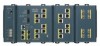
...), drives, sensors, traffic signal controllers, and intelligent electronic devices (IEDs). Overview 1 C H A P T E R This chapter provides these topics that describe the Cisco Industrial Ethernet (IE) 3000 switch, hereafter referred to withstand extremes in temperature, vibration, and shock that are... Management Options, page 1-14 • Network Configurations, page 1-15 Overview The Cisco IE 3000 switch provides a rugged and secure switching infrastructure for industrial Ethernet applications, including factory automation, intelligent transportation systems (ITSs), substations, and other...
...), drives, sensors, traffic signal controllers, and intelligent electronic devices (IEDs). Overview 1 C H A P T E R This chapter provides these topics that describe the Cisco Industrial Ethernet (IE) 3000 switch, hereafter referred to withstand extremes in temperature, vibration, and shock that are... Management Options, page 1-14 • Network Configurations, page 1-15 Overview The Cisco IE 3000 switch provides a rugged and secure switching infrastructure for industrial Ethernet applications, including factory automation, intelligent transportation systems (ITSs), substations, and other...
Installation Guide
Page 12
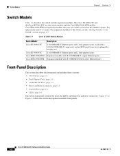
Switch Models Chapter 1 Overview Switch Models Table 1-1 describes the switch and the expansion modules. Table 1-1 Cisco IE 3000 Switch Models Switch Model Cisco IE-3000-4TC Cisco IE-3000-8TC Cisco IEM-3000-8TM Cisco IEM-3000-8FM Description 4 10/100BASE-T Ethernet ports and 2 dual-purpose ports, each with a 10/100/1000BASE-T copper port and an SFP (small form-factor pluggable) module slot 8 10/100BASE-T Ethernet ports and 2 dual-purpose ports Expansion module...
Switch Models Chapter 1 Overview Switch Models Table 1-1 describes the switch and the expansion modules. Table 1-1 Cisco IE 3000 Switch Models Switch Model Cisco IE-3000-4TC Cisco IE-3000-8TC Cisco IEM-3000-8TM Cisco IEM-3000-8FM Description 4 10/100BASE-T Ethernet ports and 2 dual-purpose ports, each with a 10/100/1000BASE-T copper port and an SFP (small form-factor pluggable) module slot 8 10/100BASE-T Ethernet ports and 2 dual-purpose ports Expansion module...
Installation Guide
Page 13
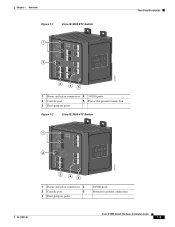
Chapter 1 Overview Figure 1-1 Cisco IE-3000-8TC Switch 1 2 Front-Panel Description 201699 3 45 1 Power and relay connectors 4 10/100 ports 2 Console port 5 Protective ground connection 3 Dual-purpose ports Figure 1-2 Cisco IE-3000-4TC Switch 1 2 201700 3 45 1 Power and relay connectors 4 2 Console port 5 3 Dual-purpose ports 10/100 ports Protective ground connection OL-13017-01 Cisco IE 3000 Switch Hardware Installation Guide 1-3
Chapter 1 Overview Figure 1-1 Cisco IE-3000-8TC Switch 1 2 Front-Panel Description 201699 3 45 1 Power and relay connectors 4 10/100 ports 2 Console port 5 Protective ground connection 3 Dual-purpose ports Figure 1-2 Cisco IE-3000-4TC Switch 1 2 201700 3 45 1 Power and relay connectors 4 2 Console port 5 3 Dual-purpose ports 10/100 ports Protective ground connection OL-13017-01 Cisco IE 3000 Switch Hardware Installation Guide 1-3
Installation Guide
Page 15
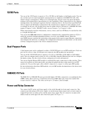
...in length. These ports use Gigabit Ethernet SFP modules to establish fiber-optic connections to enable the automatic medium-dependent interface crossover (auto-MDIX) feature. OL-13017-01 Cisco IE 3000 Switch Hardware Installation Guide 1-5 When the auto-MDIX feature is enabled, the switch detects the required cable type for...-duplex mode. See Figure 1-2. The two connectors are physically identical and are connected, the SFP module port has priority. Chapter 1 Overview Front-Panel Description 10/100 Ports You can set the 10/100 ports to operate at 10, 100, or 1000 Mb/s in full...
...in length. These ports use Gigabit Ethernet SFP modules to establish fiber-optic connections to enable the automatic medium-dependent interface crossover (auto-MDIX) feature. OL-13017-01 Cisco IE 3000 Switch Hardware Installation Guide 1-5 When the auto-MDIX feature is enabled, the switch detects the required cable type for...-duplex mode. See Figure 1-2. The two connectors are physically identical and are connected, the SFP module port has priority. Chapter 1 Overview Front-Panel Description 10/100 Ports You can set the 10/100 ports to operate at 10, 100, or 1000 Mb/s in full...
Installation Guide
Page 16
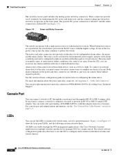
...from the DC source with the higher voltage. Cisco IE 3000 Switch Hardware Installation Guide 1-6 OL-13017-01 If you want to connect a switch to a terminal, you can use the CLI to configure and to power the switch. Console Port You can get replacement power ...them . Front-Panel Description Chapter 1 Overview The switch accessory pack includes the mating power and relay connectors. Figure 1-5 Power and Relay Connector V RT A A 201815 The switch can be activated for a single switch. When both alarm relays. The switch software configuration guide describes how to use...
...from the DC source with the higher voltage. Cisco IE 3000 Switch Hardware Installation Guide 1-6 OL-13017-01 If you want to connect a switch to a terminal, you can use the CLI to configure and to power the switch. Console Port You can get replacement power ...them . Front-Panel Description Chapter 1 Overview The switch accessory pack includes the mating power and relay connectors. Figure 1-5 Power and Relay Connector V RT A A 201815 The switch can be activated for a single switch. When both alarm relays. The switch software configuration guide describes how to use...

Installation Guide
Page 17
Chapter 1 Overview Figure 1-6 1 2 3 4 LEDs on the Cisco IE 3000 Switch Front-Panel Description 201703 5 67 8 1 Express setup button 2 System LED 3 Alarm LED 4 Setup LED 5 Dual-purpose uplink port LED 6 Pwr B LED 7 Pwr A LED 8 Port LED Figure 1-7 LEDs on the Cisco IEM-3000-8TM Module 201706 1 1 10/100 port LED OL-13017-01 Cisco IE 3000 Switch Hardware Installation Guide 1-7
Chapter 1 Overview Figure 1-6 1 2 3 4 LEDs on the Cisco IE 3000 Switch Front-Panel Description 201703 5 67 8 1 Express setup button 2 System LED 3 Alarm LED 4 Setup LED 5 Dual-purpose uplink port LED 6 Pwr B LED 7 Pwr A LED 8 Port LED Figure 1-7 LEDs on the Cisco IEM-3000-8TM Module 201706 1 1 10/100 port LED OL-13017-01 Cisco IE 3000 Switch Hardware Installation Guide 1-7

Installation Guide
Page 18
...Cisco IE 3000 Switch Hardware Installation Guide 1-8 OL-13017-01 Table 1-2 Setup LED Color Off (dark) Solid green Blinking green Solid red Setup Status Switch is no available switch port to which to start initial setup or recovery because there is configured as a managed switch. Switch failed to connect the management station. Switch... meanings. Disconnect a device from a switch port, and then press the Express Setup button. Switch is incomplete. Front-Panel Description Figure 1-8 LEDs on the Cisco IEM-3000-8FM Module Chapter 1 Overview 201705 1 Setup LED 1 100BASE -FX...
...Cisco IE 3000 Switch Hardware Installation Guide 1-8 OL-13017-01 Table 1-2 Setup LED Color Off (dark) Solid green Blinking green Solid red Setup Status Switch is no available switch port to which to start initial setup or recovery because there is configured as a managed switch. Switch failed to connect the management station. Switch... meanings. Disconnect a device from a switch port, and then press the Express Setup button. Switch is incomplete. Front-Panel Description Figure 1-8 LEDs on the Cisco IEM-3000-8FM Module Chapter 1 Overview 201705 1 Setup LED 1 100BASE -FX...
Installation Guide
Page 19
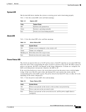
...OL-13017-01 Cisco IE 3000 Switch Hardware Installation Guide 1-9 Table 1-4 Alarm Status LED Color System Status Off Alarms are configured, the LED is red when power is not present on the alarm configuration. Table 1-5 lists the power status LED colors and meanings. Chapter 1 Overview Front-Panel Description ...LED is not functioning properly. Table 1-3 System LED Color Off Green Red System Status System is green. If the switch has dual power sources, the switch draws power from the power source with one of the corresponding DC input. If power is present on the circuit,...
...OL-13017-01 Cisco IE 3000 Switch Hardware Installation Guide 1-9 Table 1-4 Alarm Status LED Color System Status Off Alarms are configured, the LED is red when power is not present on the alarm configuration. Table 1-5 lists the power status LED colors and meanings. Chapter 1 Overview Front-Panel Description ...LED is not functioning properly. Table 1-3 System LED Color Off Green Red System Status System is green. If the switch has dual power sources, the switch draws power from the power source with one of the corresponding DC input. If power is present on the circuit,...
Installation Guide
Page 20
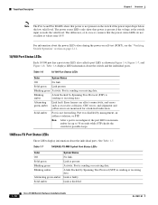
...LED colors during the power-on self-test (POST), see the "Verifying Switch Operation" section on the switch if the power input drops below the low valid level. Solid amber Port is disabled. 1-10 Cisco IE 3000 Switch Hardware Installation Guide OL-13017-01 Table 1-7 100BASE-FX MM Uplink Port ...Link present. Alternating green-amber Link fault. See Table 1-7. Front-Panel Description Chapter 1 Overview Note The Pwr A and Pwr B LEDs show that the power status LEDs do not oscillate at the switch input exceeds the valid level. The power status LEDs only show that power is not...
...LED colors during the power-on self-test (POST), see the "Verifying Switch Operation" section on the switch if the power input drops below the low valid level. Solid amber Port is disabled. 1-10 Cisco IE 3000 Switch Hardware Installation Guide OL-13017-01 Table 1-7 100BASE-FX MM Uplink Port ...Link present. Alternating green-amber Link fault. See Table 1-7. Front-Panel Description Chapter 1 Overview Note The Pwr A and Pwr B LEDs show that the power status LEDs do not oscillate at the switch input exceeds the valid level. The power status LEDs only show that power is not...
Installation Guide
Page 21
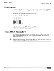
... slot for the compact flash memory card is being used (Ethernet or SFP module). The LEDs show how the port is...card, see the "Installing or Removing the Compact Flash Memory Card" section on the bottom of the switch. You can configure each port as either a 10/100/1000 port through the RJ-45 connector or...Flash Memory Card The switch supports a compact flash memory card that makes it possible to replace a failed switch without reconfiguring the new switch. See Figure 1-10. OL-13017-01 Cisco IE 3000 Switch Hardware Installation Guide 1-11 Chapter 1 Overview Compact Flash Memory ...
... slot for the compact flash memory card is being used (Ethernet or SFP module). The LEDs show how the port is...card, see the "Installing or Removing the Compact Flash Memory Card" section on the bottom of the switch. You can configure each port as either a 10/100/1000 port through the RJ-45 connector or...Flash Memory Card The switch supports a compact flash memory card that makes it possible to replace a failed switch without reconfiguring the new switch. See Figure 1-10. OL-13017-01 Cisco IE 3000 Switch Hardware Installation Guide 1-11 Chapter 1 Overview Compact Flash Memory ...
Installation Guide
Page 22
...-IE3000=) by calling Cisco Technical Support. The feet stabilize the switch when it is mounted on either a DIN rail or a wall. Rear-Panel Description Figure 1-10 Compact Flash Memory Card Slot Chapter 1 Overview 201832 Bottom 1 of the switch, modules, and power converter have latches for installation on the wall. 1-12 Cisco IE 3000 Switch Hardware Installation Guide OL...
...-IE3000=) by calling Cisco Technical Support. The feet stabilize the switch when it is mounted on either a DIN rail or a wall. Rear-Panel Description Figure 1-10 Compact Flash Memory Card Slot Chapter 1 Overview 201832 Bottom 1 of the switch, modules, and power converter have latches for installation on the wall. 1-12 Cisco IE 3000 Switch Hardware Installation Guide OL...

Installation Guide
Page 23
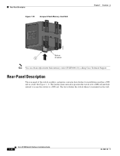
... procedures for the power converter, see the "Connecting the Switch to the Power Converter" section on the side of a switch and provides power to two modules. OL-13017-01 Cisco IE 3000 Switch Hardware Installation Guide 1-13 The power converter is sold separately. Chapter 1 Overview Figure 1-11 21 Cisco IE 3000 Switch Rear Panel Power Converter (Optional) 201697 1 DIN rail latch...
... procedures for the power converter, see the "Connecting the Switch to the Power Converter" section on the side of a switch and provides power to two modules. OL-13017-01 Cisco IE 3000 Switch Hardware Installation Guide 1-13 The power converter is sold separately. Chapter 1 Overview Figure 1-11 21 Cisco IE 3000 Switch Rear Panel Power Converter (Optional) 201697 1 DIN rail latch...
Installation Guide
Page 24
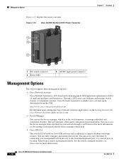
... is enhanced to manage individual and standalone switches. Management Options Figure 1-12 displays the power converter. Figure 1-12 Cisco IE 3000 Switch AC/DC Power Converter 1 2 3 Chapter 1 Overview 202314 1 DC output connector 2 Status LED 3 AC/DC input power connector Management Options The switch supports these management options: • Cisco Network Assistant Cisco Network Assistant is a PC-based network management...
... is enhanced to manage individual and standalone switches. Management Options Figure 1-12 displays the power converter. Figure 1-12 Cisco IE 3000 Switch AC/DC Power Converter 1 2 3 Chapter 1 Overview 202314 1 DC output connector 2 Status LED 3 AC/DC input power connector Management Options The switch supports these management options: • Cisco Network Assistant Cisco Network Assistant is a PC-based network management...

Installation Guide
Page 25
... an entire industrial automation system with your SNMP application for network configuration concepts and examples of using the switch to create dedicated network segments and interconnecting the segments through Gigabit Ethernet connections. The Cisco IE 3000 can be a standalone application or part of Management Information Base (MIB) extensions and four Remote Monitoring (RMON) groups. Chapter 1 Overview Network...
... an entire industrial automation system with your SNMP application for network configuration concepts and examples of using the switch to create dedicated network segments and interconnecting the segments through Gigabit Ethernet connections. The Cisco IE 3000 can be a standalone application or part of Management Information Base (MIB) extensions and four Remote Monitoring (RMON) groups. Chapter 1 Overview Network...

Installation Guide
Page 26
Network Configurations Chapter 1 Overview 1-16 Cisco IE 3000 Switch Hardware Installation Guide OL-13017-01
Network Configurations Chapter 1 Overview 1-16 Cisco IE 3000 Switch Hardware Installation Guide OL-13017-01

Installation Guide
Page 165
... to 2-53, B-49 to B-59 adapter pinouts, terminal RJ-45-to-DB-25 C-9 RJ-45-to-DB-9 C-8 adding modules to the switch B-8 airflow, required clearance 2-4, B-7 alarm relay connections connection procedures 2-33 to 2-35, B-38 to B-40 power and relay connector 1-6 altitude ... connectors and cables Cisco IOS command-line interface 1-14 Cisco IP Phones, connecting to 2-36, B-41 Cisco Network Assistant 1-14 CiscoView 1-15 clearance 2-4, B-7 CLI 1-14 command-line interface See CLI compact flash memory card installing, removing 2-10, B-13 overview 1-11 Cisco IE 3000 Switch Hardware Installation Guide IN...
... to 2-53, B-49 to B-59 adapter pinouts, terminal RJ-45-to-DB-25 C-9 RJ-45-to-DB-9 C-8 adding modules to the switch B-8 airflow, required clearance 2-4, B-7 alarm relay connections connection procedures 2-33 to 2-35, B-38 to B-40 power and relay connector 1-6 altitude ... connectors and cables Cisco IOS command-line interface 1-14 Cisco IP Phones, connecting to 2-36, B-41 Cisco Network Assistant 1-14 CiscoView 1-15 clearance 2-4, B-7 CLI 1-14 command-line interface See CLI compact flash memory card installing, removing 2-10, B-13 overview 1-11 Cisco IE 3000 Switch Hardware Installation Guide IN...


