Hardware Installation Guide
Page 16
...Cisco 860 series ISRs are powered by an external power supply adapter. These ISRs are fixed-configuration data routers that they support. The various models differ in wall-mount features. Cisco 860 Series ISRs Chapter 1 Product Overview The Cisco 860 series, Cisco 880 series, and Cisco 890 series ISRs have optional rack-mount features. The Cisco...Figure 1-1 shows the front panel details of the Cisco 860 Series Wireless ISR 231969 1 1 LEDs Cisco 860 Series, Cisco 880 Series, and Cisco 890 Series Integrated Services Routers Hardware Installation Guide 1-2 OL-16193-07 Figure ...
...Cisco 860 series ISRs are powered by an external power supply adapter. These ISRs are fixed-configuration data routers that they support. The various models differ in wall-mount features. Cisco 860 Series ISRs Chapter 1 Product Overview The Cisco 860 series, Cisco 880 series, and Cisco 890 series ISRs have optional rack-mount features. The Cisco...Figure 1-1 shows the front panel details of the Cisco 860 Series Wireless ISR 231969 1 1 LEDs Cisco 860 Series, Cisco 880 Series, and Cisco 890 Series Integrated Services Routers Hardware Installation Guide 1-2 OL-16193-07 Figure ...

Hardware Installation Guide
Page 39
... and 890 series ISRs and requires a 48-V external power adapter. USB Port The Cisco 880 series routers have one or two fans. The Cisco 860VAE series router USB port does not support eToken. The PoE module is powered up. Cisco 860 Series, Cisco 880 Series, and Cisco 890 Series Integrated Services Routers Hardware Installation Guide OL-16193-07 1-25 The fans...
... and 890 series ISRs and requires a 48-V external power adapter. USB Port The Cisco 880 series routers have one or two fans. The Cisco 860VAE series router USB port does not support eToken. The PoE module is powered up. Cisco 860 Series, Cisco 880 Series, and Cisco 890 Series Integrated Services Routers Hardware Installation Guide OL-16193-07 1-25 The fans...

Hardware Installation Guide
Page 44
xDSL = General term referring to an 880 or 890 series router by installing the PoE adapter card in the router and inserting the PoE 48-V external power adapter. 12. VDSLoPOTS = very-high-data-rate digital subscriber line 2 over Ethernet. FXO = Foreign Exchange Office. 17. SFP = small... that terminates an ISDN telephone network. IPsec = IP security. 9. G.SHDSL = (global industry standard) symmetrical high-speed DSL. 13. 3G = Third-Generation. 14. Cisco 860 Series, Cisco 880 Series, and Cisco 890 Series Integrated Services Routers Hardware Installation Guide 1-30 OL-16193-07 MDIX =...
xDSL = General term referring to an 880 or 890 series router by installing the PoE adapter card in the router and inserting the PoE 48-V external power adapter. 12. VDSLoPOTS = very-high-data-rate digital subscriber line 2 over Ethernet. FXO = Foreign Exchange Office. 17. SFP = small... that terminates an ISDN telephone network. IPsec = IP security. 9. G.SHDSL = (global industry standard) symmetrical high-speed DSL. 13. 3G = Third-Generation. 14. Cisco 860 Series, Cisco 880 Series, and Cisco 890 Series Integrated Services Routers Hardware Installation Guide 1-30 OL-16193-07 MDIX =...
Hardware Installation Guide
Page 46
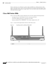
.... Additional Items The following items are not shipped with the router but are shipped with cable retention clip 1 1 1 1 Cisco Configuration Professional (Cisco CP) CD6 1 1 1 1 1. The screws must be long enough to -DB-9 console cable 1 - 1 1 External 12 VDC power supply adapter 1 1 1 1 AC power supply cable with Cisco 860VAE models unless requested through the dynamic configuration tool. 2. RJ-45...
.... Additional Items The following items are not shipped with the router but are shipped with cable retention clip 1 1 1 1 Cisco Configuration Professional (Cisco CP) CD6 1 1 1 1 1. The screws must be long enough to -DB-9 console cable 1 - 1 1 External 12 VDC power supply adapter 1 1 1 1 AC power supply cable with Cisco 860VAE models unless requested through the dynamic configuration tool. 2. RJ-45...
Hardware Installation Guide
Page 52
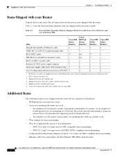
... in. 3.673 in. 1 1 5.961 in Figure 2-4. Verify the required distance before drilling the holes. Hang the router on the screws, and place the power adapter on the Underside of the router. For the Cisco 866 and Cisco 867 models, the distance is 8.2 inches (208 mm), as shown in . 231987 1 Wall-mount holes Step 2 Step 3 Insert the...
... in. 3.673 in. 1 1 5.961 in Figure 2-4. Verify the required distance before drilling the holes. Hang the router on the screws, and place the power adapter on the Underside of the router. For the Cisco 866 and Cisco 867 models, the distance is 8.2 inches (208 mm), as shown in . 231987 1 Wall-mount holes Step 2 Step 3 Insert the...
Hardware Installation Guide
Page 53
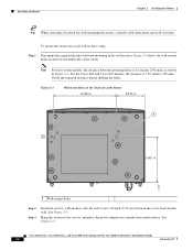
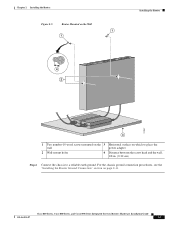
... wall power adapter 2 Wall-mount holes 4 Distance between the screw head and the wall, 1/8 in. (0.32 cm) Step 4 Connect the chassis to a reliable earth ground. Chapter 2 Installing the Router Figure 2-5 Router Mounted on the Wall 1 1 Installing the Router 4 2 231982 3 1 Two number-10 wood screws mounted on the 3 Horizontal surface on page 2-11. Cisco 860 Series, Cisco 880...
... wall power adapter 2 Wall-mount holes 4 Distance between the screw head and the wall, 1/8 in. (0.32 cm) Step 4 Connect the chassis to a reliable earth ground. Chapter 2 Installing the Router Figure 2-5 Router Mounted on the Wall 1 1 Installing the Router 4 2 231982 3 1 Two number-10 wood screws mounted on the 3 Horizontal surface on page 2-11. Cisco 860 Series, Cisco 880...
Hardware Installation Guide
Page 55
...rack, you must be mounted at the bottom of the rack. -- Step 4 Step 5 Place the power adapter on the lower screws while you insert the upper pair of screws. Install the ground wire in accordance ... the Router Warning To prevent bodily injury when mounting or servicing this unit in a partially filled rack, load the rack from the bottom to 7 mm). • For EN/IEC 60950-compliant grounding, use size 14 AWG (2... to a torque of 8 to 10 in the rack. Cisco 860 Series, Cisco 880 Series, and Cisco 890 Series Integrated Services Routers Hardware Installation Guide OL-16193-07 2-11
...rack, you must be mounted at the bottom of the rack. -- Step 4 Step 5 Place the power adapter on the lower screws while you insert the upper pair of screws. Install the ground wire in accordance ... the Router Warning To prevent bodily injury when mounting or servicing this unit in a partially filled rack, load the rack from the bottom to 7 mm). • For EN/IEC 60950-compliant grounding, use size 14 AWG (2... to a torque of 8 to 10 in the rack. Cisco 860 Series, Cisco 880 Series, and Cisco 890 Series Integrated Services Routers Hardware Installation Guide OL-16193-07 2-11
Hardware Installation Guide
Page 57
...to connect Cisco 860 series, Cisco 880 series, and Cisco 890 series Integrated Services Routers (ISRs) to an GE WAN Port, page 3-22 • Connecting an xDSL Line, page 3-23 • Connecting Power over Ethernet (PoE), and a network. The chapter contains the following sections: • Preparing to Connect the Router, page ... page 3-7 • Connecting a Modem to the Auxiliary Port, page 3-8 • Connecting the 3G Card, page 3-9 • Installing the 3G Adapter for Extended Cable/Antenna, page 3-15 • Connecting an FE Line to an FE WAN Port, page 3-21 • Connecting an GE Line ...
...to connect Cisco 860 series, Cisco 880 series, and Cisco 890 series Integrated Services Routers (ISRs) to an GE WAN Port, page 3-22 • Connecting an xDSL Line, page 3-23 • Connecting Power over Ethernet (PoE), and a network. The chapter contains the following sections: • Preparing to Connect the Router, page ... page 3-7 • Connecting a Modem to the Auxiliary Port, page 3-8 • Connecting the 3G Card, page 3-9 • Installing the 3G Adapter for Extended Cable/Antenna, page 3-15 • Connecting an FE Line to an FE WAN Port, page 3-21 • Connecting an GE Line ...
Hardware Installation Guide
Page 81
...) status. Statement 1028 Warning This product must be removed to a power-over Ethernet (PoE) power adapter to your service provider and correctly configured so that the internal PoE is inserted Note The DSL line must also be provisioned by your router. On Cisco 860VAE routers, check the DSL Link LED. Statement 353 Figure 3-24 shows how...
...) status. Statement 1028 Warning This product must be removed to a power-over Ethernet (PoE) power adapter to your service provider and correctly configured so that the internal PoE is inserted Note The DSL line must also be provisioned by your router. On Cisco 860VAE routers, check the DSL Link LED. Statement 353 Figure 3-24 shows how...
Hardware Installation Guide
Page 82
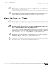
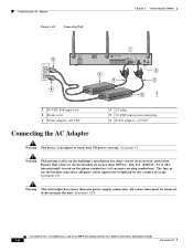
...de-energize the unit. Connecting the AC Adapter Figure 3-24 Connecting PoE Chapter 3 Connecting the Router 1 4 5 3 2 2 4 6 231995 1 48-VDC PoE input jack 2 Power cord 3 Power adapter-48 VDC Connecting the AC Adapter 4 AC plug 5 12-VDC input power-jack plug 6 Power adapter-12 VDC Warning The device is used on...the country of usage. Statement 1028 Cisco 860 Series, Cisco 880 Series, and Cisco 890 Series Integrated Services Routers Hardware Installation Guide 3-26 OL-16193-07 The fuse or circuit breaker must be removed to work with TN power systems. Statement 19 Warning This ...
...de-energize the unit. Connecting the AC Adapter Figure 3-24 Connecting PoE Chapter 3 Connecting the Router 1 4 5 3 2 2 4 6 231995 1 48-VDC PoE input jack 2 Power cord 3 Power adapter-48 VDC Connecting the AC Adapter 4 AC plug 5 12-VDC input power-jack plug 6 Power adapter-12 VDC Warning The device is used on...the country of usage. Statement 1028 Cisco 860 Series, Cisco 880 Series, and Cisco 890 Series Integrated Services Routers Hardware Installation Guide 3-26 OL-16193-07 The fuse or circuit breaker must be removed to work with TN power systems. Statement 19 Warning This ...
Hardware Installation Guide
Page 83
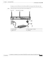
Figure 3-25 Connecting the AC Adapter 4 1 12-VDC plug 2 Power cord 1 2 3 3 Power adapter-12 VDC 4 AC plug 231996 Cisco 860 Series, Cisco 880 Series, and Cisco 890 Series Integrated Services Routers Hardware Installation Guide OL-16193-07 3-27 Chapter 3 Connecting the Router Connecting the AC Adapter To connect your Cisco 860 series or Cisco 880 series ISR to an AC power outlet, follow these steps: Step 1 Connect the router to an AC power outlet as shown in Figure 3-25.
Figure 3-25 Connecting the AC Adapter 4 1 12-VDC plug 2 Power cord 1 2 3 3 Power adapter-12 VDC 4 AC plug 231996 Cisco 860 Series, Cisco 880 Series, and Cisco 890 Series Integrated Services Routers Hardware Installation Guide OL-16193-07 3-27 Chapter 3 Connecting the Router Connecting the AC Adapter To connect your Cisco 860 series or Cisco 880 series ISR to an AC power outlet, follow these steps: Step 1 Connect the router to an AC power outlet as shown in Figure 3-25.
Hardware Installation Guide
Page 84
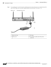
Figure 3-26 Securing the Power Cord 3 2 4 1 270659 1 Power lock clip 2 Power cord 3 DC plug 4 Lock holes on either side of the DC plug, and secure the retaining clip into the router chassis. Connecting the AC Adapter Chapter 3 Connecting the Router Step 2 To secure the power cord to the router, attach the power lock clip to the power cord, slide the clip to the end of the power connector Cisco 860 Series, Cisco 880 Series, and Cisco 890 Series Integrated Services Routers Hardware Installation Guide 3-28 OL-16193-07 See Figure 3-26.
Figure 3-26 Securing the Power Cord 3 2 4 1 270659 1 Power lock clip 2 Power cord 3 DC plug 4 Lock holes on either side of the DC plug, and secure the retaining clip into the router chassis. Connecting the AC Adapter Chapter 3 Connecting the Router Step 2 To secure the power cord to the router, attach the power lock clip to the power cord, slide the clip to the end of the power connector Cisco 860 Series, Cisco 880 Series, and Cisco 890 Series Integrated Services Routers Hardware Installation Guide 3-28 OL-16193-07 See Figure 3-26.
Hardware Installation Guide
Page 85
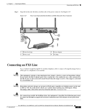
.... Warning Hazardous network voltages are present in WAN ports regardless of whether power to the unit is activated by an incoming call. Cisco 860 Series, Cisco 880 Series, and Cisco 890 Series Integrated Services Routers Hardware Installation Guide OL-16193-07 3-29 See Figure 3-27. Warning... equipment is a source of hazardous voltage. Chapter 3 Connecting the Router Connecting an FXS Line Step 3 Snap the latches into the holes on Either Side of the Power Connector 4 1 Power lock clip 2 Power cord 1 2 3 3 Power adapter 4 AC plug 270800 Connecting an FXS Line Use a standard straight...
.... Warning Hazardous network voltages are present in WAN ports regardless of whether power to the unit is activated by an incoming call. Cisco 860 Series, Cisco 880 Series, and Cisco 890 Series Integrated Services Routers Hardware Installation Guide OL-16193-07 3-29 See Figure 3-27. Warning... equipment is a source of hazardous voltage. Chapter 3 Connecting the Router Connecting an FXS Line Step 3 Snap the latches into the holes on Either Side of the Power Connector 4 1 Power lock clip 2 Power cord 1 2 3 3 Power adapter 4 AC plug 270800 Connecting an FXS Line Use a standard straight...
Hardware Installation Guide
Page 104
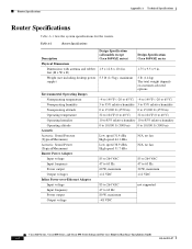
... humidity Operating altitude Acoustic Acoustic: Sound Pressure (Typical/Maximum) Acoustic: Sound Power (Typical/Maximum) Router Power Adapter Input voltage Input frequency Power output Output voltages Inline Power-over-Ethernet Adapter Input voltage Input frequency Power output Output voltage Design Specification (all models except Cisco 860VAE series) Design Specification Cisco 860VAE series 1.9 x 12.8 x 10.4 in. 1.75 x 9.5 x 9 in. 5.5 lb (2.5 kg), maximum 3 lb...
... humidity Operating altitude Acoustic Acoustic: Sound Pressure (Typical/Maximum) Acoustic: Sound Power (Typical/Maximum) Router Power Adapter Input voltage Input frequency Power output Output voltages Inline Power-over-Ethernet Adapter Input voltage Input frequency Power output Output voltage Design Specification (all models except Cisco 860VAE series) Design Specification Cisco 860VAE series 1.9 x 12.8 x 10.4 in. 1.75 x 9.5 x 9 in. 5.5 lb (2.5 kg), maximum 3 lb...


