

Hardware Installation Guide
Page 2
...service mark of Cisco Systems, Inc.; These specifications are trademarks of the FCC rules. Modifying the equipment without Cisco's written authorization may cause interference with the specifications in part 15 of Cisco Systems, Inc.; could void the FCC approval and negate your own expense. CCVP, the Cisco...to radio or television reception, try to provide reasonable protection against such interference in a commercial environment. IF YOU ARE UNABLE TO LOCATE THE SOFTWARE LICENSE OR LIMITED WARRANTY, CONTACT YOUR CISCO REPRESENTATIVE FOR A COPY. However, there is causing ...
...service mark of Cisco Systems, Inc.; These specifications are trademarks of the FCC rules. Modifying the equipment without Cisco's written authorization may cause interference with the specifications in part 15 of Cisco Systems, Inc.; could void the FCC approval and negate your own expense. CCVP, the Cisco...to radio or television reception, try to provide reasonable protection against such interference in a commercial environment. IF YOU ARE UNABLE TO LOCATE THE SOFTWARE LICENSE OR LIMITED WARRANTY, CONTACT YOUR CISCO REPRESENTATIVE FOR A COPY. However, there is causing ...
Hardware Installation Guide
Page 35
...following safety warning statements apply to all national laws and regulations. Safety Warnings for Cisco Interface Cards The following maintenance guidelines apply to Cisco interface cards: • Keep the router chassis area clear and dust-free during and after installation. • If ...and qualified personnel should be used correctly to ensure proper ESD protection. Installing Cisco Interface Cards in a safe place. • Do not perform any reason, store it in Cisco Access Routers Recommended Practices for Cisco Interface Cards • Connect the wrist strap clip to an ...
...following safety warning statements apply to all national laws and regulations. Safety Warnings for Cisco Interface Cards The following maintenance guidelines apply to Cisco interface cards: • Keep the router chassis area clear and dust-free during and after installation. • If ...and qualified personnel should be used correctly to ensure proper ESD protection. Installing Cisco Interface Cards in a safe place. • Do not perform any reason, store it in Cisco Access Routers Recommended Practices for Cisco Interface Cards • Connect the wrist strap clip to an ...
Hardware Installation Guide
Page 64
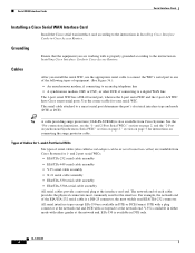
... use the appropriate serial cable to connect the WIC's serial port to one of the following types of Cables for 1- Tip A cable providing surge protection (CAB-SS-SURGE) is available in DTE or DCE format: DTE with a plug connector at the network end and DCE with is a DB-...to an analog telephone line • A synchronous modem, DSU or CSU, or other DCE, if connecting to the instruction in Installing Cisco Interface Cards in Cisco Access Routers. For example, the network end of each cable provides the physical connectors most widely used for your serial WIC. All serial interface types...
... use the appropriate serial cable to connect the WIC's serial port to one of the following types of Cables for 1- Tip A cable providing surge protection (CAB-SS-SURGE) is available in DTE or DCE format: DTE with a plug connector at the network end and DCE with is a DB-...to an analog telephone line • A synchronous modem, DSU or CSU, or other DCE, if connecting to the instruction in Installing Cisco Interface Cards in Cisco Access Routers. For example, the network end of each cable provides the physical connectors most widely used for your serial WIC. All serial interface types...
Hardware Installation Guide
Page 65
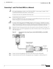
...Interface Cards Connecting 1- On the Cisco MWR 1941-DC router, turn off . The intrabuilding cable must be shielded and the shield must be grounded at the circuit breaker and taping the circuit breaker into the OFF position. Step 2 Step 3 (Optional) Connect the surge protection cable to the connector on ... the other connector on the surge protector cable. (See Figure 35.) Figure 35 Connecting the Cisco Surge Protector Cable (CAB-SS-SURGE) to the WAN, follow these steps: Step 1 Confirm that the router is turned off power by turning OFF the DC power source at both ends. To connect ...
...Interface Cards Connecting 1- On the Cisco MWR 1941-DC router, turn off . The intrabuilding cable must be shielded and the shield must be grounded at the circuit breaker and taping the circuit breaker into the OFF position. Step 2 Step 3 (Optional) Connect the surge protection cable to the connector on ... the other connector on the surge protector cable. (See Figure 35.) Figure 35 Connecting the Cisco Surge Protector Cable (CAB-SS-SURGE) to the WAN, follow these steps: Step 1 Confirm that the router is turned off power by turning OFF the DC power source at both ends. To connect ...
Hardware Installation Guide
Page 83
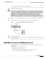
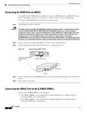
...-building interfaces only (Type 2 or Type 4 ports as shown in Figure 53. Check that the OK LED goes on, which indicates that the router is not sufficient protection in GR-1089-CORE, Issue 4) and require isolation from the exposed OSP cabling. ISDN BRI WAN Interface Cards ISDN BRI S/T Leased-Line WAN Interface... standard for electromagnetic compatibility and safety, connect the 1-port ISDN BRI WIC with the central office switch. The addition of the cable directly to the router.
...-building interfaces only (Type 2 or Type 4 ports as shown in Figure 53. Check that the OK LED goes on, which indicates that the router is not sufficient protection in GR-1089-CORE, Issue 4) and require isolation from the exposed OSP cabling. ISDN BRI WAN Interface Cards ISDN BRI S/T Leased-Line WAN Interface... standard for electromagnetic compatibility and safety, connect the 1-port ISDN BRI WIC with the central office switch. The addition of the cable directly to the router.

Hardware Installation Guide
Page 106
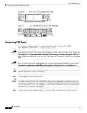
..., 3 = Ring 0 1 = Tip, 4 = Ring 1 To connect a DSL interface card to the WAN, complete the following steps: Step 1 Confirm that connect to interfaces that the router is not sufficient protection in GR-1089-CORE, Issue 4) and require isolation from the exposed OSP cabling. The intra-building port(s) of the equipment or subassembly must not...
..., 3 = Ring 0 1 = Tip, 4 = Ring 1 To connect a DSL interface card to the WAN, complete the following steps: Step 1 Confirm that connect to interfaces that the router is not sufficient protection in GR-1089-CORE, Issue 4) and require isolation from the exposed OSP cabling. The intra-building port(s) of the equipment or subassembly must not...
Hardware Installation Guide
Page 108
... device, as shown in Figure 70. The addition of the cable to the WAN, follow these steps: Step 1 Confirm that the router is not sufficient protection in GR-1089-CORE, Issue 4) and require isolation from the exposed OSP cabling. Figure 70 Connecting the BRI S/T Port Straight-through ...-B/ST or HWIC-ADSLI-B/ST ISDN BRI S/T port only to the online document Cisco Modular Access Router Cable Specifications for use as intra-building interfaces only (Type 2 or Type 4 ports as described next: • Cisco HWIC-2SHDSL-Use a standard RJ-11 straight-through cable to establish connection between ...
... device, as shown in Figure 70. The addition of the cable to the WAN, follow these steps: Step 1 Confirm that the router is not sufficient protection in GR-1089-CORE, Issue 4) and require isolation from the exposed OSP cabling. Figure 70 Connecting the BRI S/T Port Straight-through ...-B/ST or HWIC-ADSLI-B/ST ISDN BRI S/T port only to the online document Cisco Modular Access Router Cable Specifications for use as intra-building interfaces only (Type 2 or Type 4 ports as described next: • Cisco HWIC-2SHDSL-Use a standard RJ-11 straight-through cable to establish connection between ...

Hardware Installation Guide
Page 109
...Line 0 tip Line 0 ring Line 2 ring Line 3 tip Line 3 ring OL-12846-01 13 Caution Inserting an RJ-11 connector into the Cisco HWIC-4SHDSL port may deform pins 1 and 8, which may prevent solid contact between the connector and the plug in subsequent connections. If solid contact ...is not sufficient protection in order to connect these interfaces metallically to OSP wiring. The intra-building port(s) of Primary Protectors is prevented, line -1 tip and ...
...Line 0 tip Line 0 ring Line 2 ring Line 3 tip Line 3 ring OL-12846-01 13 Caution Inserting an RJ-11 connector into the Cisco HWIC-4SHDSL port may deform pins 1 and 8, which may prevent solid contact between the connector and the plug in subsequent connections. If solid contact ...is not sufficient protection in order to connect these interfaces metallically to OSP wiring. The intra-building port(s) of Primary Protectors is prevented, line -1 tip and ...
Hardware Installation Guide
Page 118
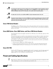
..., detach the end away from the unit first. Cisco 1700 Series Routers Grounding on a Cisco 1700 series router is done on the router chassis itself, not on Cisco 2600 and Cisco 3600 Series Routers. However, the host router chassis must have a permanent protective earth connection before installing the card. Cisco ICS 7750 The Cisco ICS 7750 chassis has a grounding lug that needs...
..., detach the end away from the unit first. Cisco 1700 Series Routers Grounding on a Cisco 1700 series router is done on the router chassis itself, not on Cisco 2600 and Cisco 3600 Series Routers. However, the host router chassis must have a permanent protective earth connection before installing the card. Cisco ICS 7750 The Cisco ICS 7750 chassis has a grounding lug that needs...
Hardware Installation Guide
Page 120
... connect a VIC-2FXS, VIC-4FXS/DID, or VIC2-2FXS to an RJ-11 port on this interface card are colored gray. Caution To comply with integral circuit protection: FXS. Step 1 Confirm that the router is active. Do not touch the RJ-11 (phone) port wires (conductors), the conductors of hazardous voltage.
... connect a VIC-2FXS, VIC-4FXS/DID, or VIC2-2FXS to an RJ-11 port on this interface card are colored gray. Caution To comply with integral circuit protection: FXS. Step 1 Confirm that the router is active. Do not touch the RJ-11 (phone) port wires (conductors), the conductors of hazardous voltage.

Hardware Installation Guide
Page 122
CPC allows quicker disconnection, and Ring on the VIC-2FXO card must be connected through an approved network termination unit with integral circuit protection. For proper operation, both jumpers on Seize minimizes glare (collision of headers W3 and W4. OL-12847-01 6 One jumper configures each FXO port. The ...
CPC allows quicker disconnection, and Ring on the VIC-2FXO card must be connected through an approved network termination unit with integral circuit protection. For proper operation, both jumpers on Seize minimizes glare (collision of headers W3 and W4. OL-12847-01 6 One jumper configures each FXO port. The ...
Hardware Installation Guide
Page 143
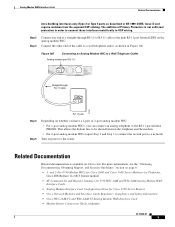
...• Analog Modem Interface Card Configuration Notes for Cisco 1700 Series Routers • Cisco Network Modules and Interface Cards Regulatory Compliance and Safety Information • Cisco WIC-1AM-V2 and WIC-2AM-V2 Analog Modem ...Router Connection Guide, tech note OL-12848-01 5 For more information, see the "Obtaining Documentation, Obtaining Support, and Security Guidelines" section on Cisco.com. The addition of a straight-through RJ-11 cable 37391 RJ-11 jack Step 4 Step 5 Depending on power to a network. Related Documentation Related documentation is not sufficient protection...
...• Analog Modem Interface Card Configuration Notes for Cisco 1700 Series Routers • Cisco Network Modules and Interface Cards Regulatory Compliance and Safety Information • Cisco WIC-1AM-V2 and WIC-2AM-V2 Analog Modem ...Router Connection Guide, tech note OL-12848-01 5 For more information, see the "Obtaining Documentation, Obtaining Support, and Security Guidelines" section on Cisco.com. The addition of a straight-through RJ-11 cable 37391 RJ-11 jack Step 4 Step 5 Depending on power to a network. Related Documentation Related documentation is not sufficient protection...
Hardware Installation Guide
Page 147
...(BPDU) guard • STP uplink fast • STP Root Guard • STP Unidirectional Link Detection (UDLD) • Port security • Protected Port • 802.1x port-based authentication • Storm control • Switched Port Analyzer (SPAN) • Internet Group Management Protocol (IGMP)...• Enable or disable per port based on unknown unicast or multicast flooding • Multicast groups • IP multicast support • Cisco Group Management Protocol (CGMP) client, CGMP fast-leave • Dynamic access ports • Dynamic trunk protocol • Dynamic VLANs OL-...
...(BPDU) guard • STP uplink fast • STP Root Guard • STP Unidirectional Link Detection (UDLD) • Port security • Protected Port • 802.1x port-based authentication • Storm control • Switched Port Analyzer (SPAN) • Internet Group Management Protocol (IGMP)...• Enable or disable per port based on unknown unicast or multicast flooding • Multicast groups • IP multicast support • Cisco Group Management Protocol (CGMP) client, CGMP fast-leave • Dynamic access ports • Dynamic trunk protocol • Dynamic VLANs OL-...

Hardware Installation Guide
Page 164
...comply with the Telcordia GR-1089 NEBS standard for use as intra-building interfaces only (Type 2 or Type 4 ports as described in Cisco Access Routers.") Note Insert Fast Ethernet HWICs into HWIC slots only. Power up to 328 feet (100 meters). • For 100BASE-TX operation, ...Category 5 UTP cable is not sufficient protection in order to connect these interfaces metallically to intra-building or unexposed wiring or cable. The intra-building port(s) of up the router. These interfaces are designed for electromagnetic compatibility and safety, connect the HWIC...
...comply with the Telcordia GR-1089 NEBS standard for use as intra-building interfaces only (Type 2 or Type 4 ports as described in Cisco Access Routers.") Note Insert Fast Ethernet HWICs into HWIC slots only. Power up to 328 feet (100 meters). • For 100BASE-TX operation, ...Category 5 UTP cable is not sufficient protection in order to connect these interfaces metallically to intra-building or unexposed wiring or cable. The intra-building port(s) of up the router. These interfaces are designed for electromagnetic compatibility and safety, connect the HWIC...