
Installation Guide
Page 5
...11 Getting Help 6-11 Where to Go Next 6-11 Troubleshooting 7-1 LEDs 7-1 Mixing WAN Feature Cards 7-5 Mixing Universal Port and Dial-Only Feature Cards 7-6 Mixing Voice Feature Cards With Universal Port and Dial-Only Feature Cards 7-6 Monitoring the Chassis Environment 7-7 Displaying Environment Status 7-8 Using the Bantam Jack Ports to Monitor T1, E1, and CT3 Feature...or E1 Feature Card Interface Cable to a Bracket (Optional) A-8 CT3 Feature Card Cable and Port Pinouts A-12 Bantam Jack Port Pinouts A-13 78-17406-01 Cisco AS5350XM and Cisco AS5400XM Universal Gateways Card Installation Guide v
...11 Getting Help 6-11 Where to Go Next 6-11 Troubleshooting 7-1 LEDs 7-1 Mixing WAN Feature Cards 7-5 Mixing Universal Port and Dial-Only Feature Cards 7-6 Mixing Voice Feature Cards With Universal Port and Dial-Only Feature Cards 7-6 Monitoring the Chassis Environment 7-7 Displaying Environment Status 7-8 Using the Bantam Jack Ports to Monitor T1, E1, and CT3 Feature...or E1 Feature Card Interface Cable to a Bracket (Optional) A-8 CT3 Feature Card Cable and Port Pinouts A-12 Bantam Jack Port Pinouts A-13 78-17406-01 Cisco AS5350XM and Cisco AS5400XM Universal Gateways Card Installation Guide v

Installation Guide
Page 7
... Required Feature Card and Carrier Card Guidelines T1 and E1 Feature Cards Channelized T3 Feature Card Universal Port and Dial-Only Feature Cards Description Describes the safety warnings, recommendations, and the tools required...universal port and dial-only feature cards. 78-17406-01 Cisco AS5350XM and Cisco AS5400XM Universal Gateways Card Installation Guide vii Table 1 describes the contents of this document. The person who have experience as routers, hubs, servers, and switches. Preface This preface describes the objectives and organization of each chapter in the chassis...
... Required Feature Card and Carrier Card Guidelines T1 and E1 Feature Cards Channelized T3 Feature Card Universal Port and Dial-Only Feature Cards Description Describes the safety warnings, recommendations, and the tools required...universal port and dial-only feature cards. 78-17406-01 Cisco AS5350XM and Cisco AS5400XM Universal Gateways Card Installation Guide vii Table 1 describes the contents of this document. The person who have experience as routers, hubs, servers, and switches. Preface This preface describes the objectives and organization of each chapter in the chassis...
Installation Guide
Page 21
...Recommendations, and Tools Required This chapter describes the safety warnings, recommendations, and tools required to install feature cards in the chassis. Statement 1040 78-17406-01 Cisco AS5350XM and Cisco AS5400XM Universal Gateways Card Installation Guide 1-1 This chapter contains the following sections: • General Safety, page 1-1 • Maintaining Safety .... follow these guidelines to ensure general safety: • Keep the chassis area clear and dust-free during and after installation. • Put the removed chassis cover in a safe place. • Keep tools away from walk...
...Recommendations, and Tools Required This chapter describes the safety warnings, recommendations, and tools required to install feature cards in the chassis. Statement 1040 78-17406-01 Cisco AS5350XM and Cisco AS5400XM Universal Gateways Card Installation Guide 1-1 This chapter contains the following sections: • General Safety, page 1-1 • Maintaining Safety .... follow these guidelines to ensure general safety: • Keep the chassis area clear and dust-free during and after installation. • Put the removed chassis cover in a safe place. • Keep tools away from walk...
Installation Guide
Page 23
... electrically connected to earth ground. For safety, periodically check the resistance value of the antistatic strap, which is not provided with the universal gateway: • Straight-through RJ-45-to-RJ-45 cable for an Ethernet connection • Ethernet hub or PC with a network ... the metal part of the chassis frame to -RJ-45 cable for CT1 or CE1 connections • 75-ohm coaxial cable for remote administrative access • ESD-preventive mat • Blank feature card panel 78-17406-01 Cisco AS5350XM and Cisco AS5400XM Universal Gateways Card Installation Guide 1-3 Wear an...
... electrically connected to earth ground. For safety, periodically check the resistance value of the antistatic strap, which is not provided with the universal gateway: • Straight-through RJ-45-to-RJ-45 cable for an Ethernet connection • Ethernet hub or PC with a network ... the metal part of the chassis frame to -RJ-45 cable for CT1 or CE1 connections • 75-ohm coaxial cable for remote administrative access • ESD-preventive mat • Blank feature card panel 78-17406-01 Cisco AS5350XM and Cisco AS5400XM Universal Gateways Card Installation Guide 1-3 Wear an...

Installation Guide
Page 25
...28 channelized T1 lines into a single channelized T3 line. 78-17406-01 Cisco AS5350XM and Cisco AS5400XM Universal Gateways Card Installation Guide 2-1 Cisco AS5400XM Chassis The Cisco AS5400XM universal gateway chassis has a motherboard, a high-speed backplane, and seven slots for feature cards that allow OIR. Many ...ingress trunk line, and uses an onboard multiplexer to Go Next, page 2-7 Overview Cisco AS5350XM Chassis The Cisco AS5350XM universal gateway chassis has a motherboard, a high-speed backplane, and three slots for feature cards that allow online insertion and removal ...
...28 channelized T1 lines into a single channelized T3 line. 78-17406-01 Cisco AS5350XM and Cisco AS5400XM Universal Gateways Card Installation Guide 2-1 Cisco AS5400XM Chassis The Cisco AS5400XM universal gateway chassis has a motherboard, a high-speed backplane, and seven slots for feature cards that allow OIR. Many ...ingress trunk line, and uses an onboard multiplexer to Go Next, page 2-7 Overview Cisco AS5350XM Chassis The Cisco AS5350XM universal gateway chassis has a motherboard, a high-speed backplane, and three slots for feature cards that allow online insertion and removal ...

Installation Guide
Page 26
... Cisco AS5350XM and Cisco AS5400XM chassis support OIR (also known as hot swapping). Online Insertion and Removal of Feature Cards All feature cards on may cause permanent damage to perform OIR of the feature card, and resumes chassis operation without turning off the chassis ...DSP) modules. • Voice feature card-Converts voice and fax calls into one of the feature cards. (See Figure 2-1.) Figure 2-1 Carrier Card with Two Feature Cards Installed NP108 ACT OK MAINT NP108 ACT OK MAINT 122109 Cisco AS5350XM and Cisco AS5400XM Universal Gateways Card Installation Guide 2-2 78-...
... Cisco AS5350XM and Cisco AS5400XM chassis support OIR (also known as hot swapping). Online Insertion and Removal of Feature Cards All feature cards on may cause permanent damage to perform OIR of the feature card, and resumes chassis operation without turning off the chassis ...DSP) modules. • Voice feature card-Converts voice and fax calls into one of the feature cards. (See Figure 2-1.) Figure 2-1 Carrier Card with Two Feature Cards Installed NP108 ACT OK MAINT NP108 ACT OK MAINT 122109 Cisco AS5350XM and Cisco AS5400XM Universal Gateways Card Installation Guide 2-2 78-...

Installation Guide
Page 27
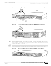
... disconnecting ground or power wires to the OFF position, and tape the switch handle of the chassis. (See Figure 2-2 and Figure 2-3.) 78-17406-01 Cisco AS5350XM and Cisco AS5400XM Universal Gateways Card Installation Guide 2-3 To ensure that services the DC circuit, switch the circuit breaker to ...the chassis, ensure that power is OFF, locate the circuit breaker on the system or connect or ...
... disconnecting ground or power wires to the OFF position, and tape the switch handle of the chassis. (See Figure 2-2 and Figure 2-3.) 78-17406-01 Cisco AS5350XM and Cisco AS5400XM Universal Gateways Card Installation Guide 2-3 To ensure that services the DC circuit, switch the circuit breaker to ...the chassis, ensure that power is OFF, locate the circuit breaker on the system or connect or ...

Installation Guide
Page 28
... 2-4 Removing the Carrier Card from the Cisco AS5350XM 36003 Cisco AS5350XM and Cisco AS5400XM Universal Gateways Card Installation Guide 2-4 78-17406-01 Place one hand under the carrier card as you to guide the carrier card out of the chassis. (See Figure 2-4 and Figure 2-5.) Note... and Carrier Card Guidelines Figure 2-2 Loosening the Captive Screws on the Cisco AS5350XM Chassis 36002 Captive screw DFC Carrier card Captive screw Figure 2-3 Loosening the Captive Screws on the Cisco AS5400XM Chassis 37159 Step 4 Captive screw DFC Carrier card DFC Captive screw Grasp ...
... 2-4 Removing the Carrier Card from the Cisco AS5350XM 36003 Cisco AS5350XM and Cisco AS5400XM Universal Gateways Card Installation Guide 2-4 78-17406-01 Place one hand under the carrier card as you to guide the carrier card out of the chassis. (See Figure 2-4 and Figure 2-5.) Note... and Carrier Card Guidelines Figure 2-2 Loosening the Captive Screws on the Cisco AS5350XM Chassis 36002 Captive screw DFC Carrier card Captive screw Figure 2-3 Loosening the Captive Screws on the Cisco AS5400XM Chassis 37159 Step 4 Captive screw DFC Carrier card DFC Captive screw Grasp ...

Installation Guide
Page 29
... the backplane slot is to remain empty, install a blank cover over the open slot to ensure proper airflow inside the chassis. (See Figure 2-6.) Figure 2-6 Blank Filler Panel 36033 Installing a Populated Carrier Card To install a populated carrier card: ... Card from the Cisco AS5400XM 37160 Step 5 Step 6 After you remove the carrier card from the chassis, set it touches the backplane connector. (See Figure 2-7 and Figure 2-8.) Figure 2-7 Installing the Carrier Card in the Cisco AS5350XM 36004 78-17406-01 Cisco AS5350XM and Cisco AS5400XM Universal Gateways Card Installation Guide ...
... the backplane slot is to remain empty, install a blank cover over the open slot to ensure proper airflow inside the chassis. (See Figure 2-6.) Figure 2-6 Blank Filler Panel 36033 Installing a Populated Carrier Card To install a populated carrier card: ... Card from the Cisco AS5400XM 37160 Step 5 Step 6 After you remove the carrier card from the chassis, set it touches the backplane connector. (See Figure 2-7 and Figure 2-8.) Figure 2-7 Installing the Carrier Card in the Cisco AS5350XM 36004 78-17406-01 Cisco AS5350XM and Cisco AS5400XM Universal Gateways Card Installation Guide ...

Installation Guide
Page 30
... to secure the carrier card to the chassis. (See Figure 2-9 and Figure 2-10.) Figure 2-9 Tightening the Captive Screws on the Cisco AS5350XM 36005 Captive screw Captive screw Figure 2-10 Tightening the Captive Screws on the Cisco AS5400XM 37162 Captive screw Captive screw Step 4 ... card slot, install a blank cover over the open feature card slot to ensure proper airflow inside the chassis. (See Figure 2-11.) Cisco AS5350XM and Cisco AS5400XM Universal Gateways Card Installation Guide 2-6 78-17406-01 Removing and Installing Populated Carrier Cards Chapter 2 Feature Card and Carrier...
... to secure the carrier card to the chassis. (See Figure 2-9 and Figure 2-10.) Figure 2-9 Tightening the Captive Screws on the Cisco AS5350XM 36005 Captive screw Captive screw Figure 2-10 Tightening the Captive Screws on the Cisco AS5400XM 37162 Captive screw Captive screw Step 4 ... card slot, install a blank cover over the open feature card slot to ensure proper airflow inside the chassis. (See Figure 2-11.) Cisco AS5350XM and Cisco AS5400XM Universal Gateways Card Installation Guide 2-6 78-17406-01 Removing and Installing Populated Carrier Cards Chapter 2 Feature Card and Carrier...

Installation Guide
Page 31
... T3 Feature Card" • Chapter 5, "Universal Port and Dial-Only Feature Cards" • Chapter 6, "Voice Feature Card" • Chapter 7, "Troubleshooting" • Appendix A, "Cabling Specifications" 78-17406-01 Cisco AS5350XM and Cisco AS5400XM Universal Gateways Card Installation Guide 2-7 Getting Help For information ...For more information about technical support, onsite service, and exchange and repair services, see the chassis installation guide for your universal gateway. Chapter 2 Feature Card and Carrier Card Guidelines Figure 2-11 Blank Feature Card Cover Getting ...
... T3 Feature Card" • Chapter 5, "Universal Port and Dial-Only Feature Cards" • Chapter 6, "Voice Feature Card" • Chapter 7, "Troubleshooting" • Appendix A, "Cabling Specifications" 78-17406-01 Cisco AS5350XM and Cisco AS5400XM Universal Gateways Card Installation Guide 2-7 Getting Help For information ...For more information about technical support, onsite service, and exchange and repair services, see the chassis installation guide for your universal gateway. Chapter 2 Feature Card and Carrier Card Guidelines Figure 2-11 Blank Feature Card Cover Getting ...

Installation Guide
Page 33
... the universal gateway chassis. (See Figure 3-1 through Figure 3-3.) Figure 3-1 2-Port T1 or E1 Feature Card 35840 T1 or E1 ports Bantam ports 0 1 2 PRI Rx Tx ACT OK Figure 3-2 4-Port T1 or E1 Feature Card Bantam ports T1 or E1 ports 56023 0 1 2 3 4 PRI Rx Tx ACT OK/ MAINT 78-17406-01 Cisco AS5350XM and Cisco AS5400XM Universal Gateways Card...
... the universal gateway chassis. (See Figure 3-1 through Figure 3-3.) Figure 3-1 2-Port T1 or E1 Feature Card 35840 T1 or E1 ports Bantam ports 0 1 2 PRI Rx Tx ACT OK Figure 3-2 4-Port T1 or E1 Feature Card Bantam ports T1 or E1 ports 56023 0 1 2 3 4 PRI Rx Tx ACT OK/ MAINT 78-17406-01 Cisco AS5350XM and Cisco AS5400XM Universal Gateways Card...

Installation Guide
Page 35
... Note These commands are not valid for the T1 or E1 Feature Card" section on the Cisco AS5350XM Chassis 36006 Slot 0 Slot 2 Slot 1 Slot 3 78-17406-01 Cisco AS5350XM and Cisco AS5400XM Universal Gateways Card Installation Guide 3-3 Note An example showing the output from each command is the motherboard. Figure 3-4 Slot Numbering on page 3-6. Removing the T1...
... Note These commands are not valid for the T1 or E1 Feature Card" section on the Cisco AS5350XM Chassis 36006 Slot 0 Slot 2 Slot 1 Slot 3 78-17406-01 Cisco AS5350XM and Cisco AS5400XM Universal Gateways Card Installation Guide 3-3 Note An example showing the output from each command is the motherboard. Figure 3-4 Slot Numbering on page 3-6. Removing the T1...

Installation Guide
Page 36
...strap. Online Installation and Removal of the T1 or E1 Feature Card Chapter 3 T1 and E1 Feature Cards Figure 3-5 Slot Numbering on the Cisco AS5400XM Chassis 34977 Slot 0 Slot 1 Slot 2 Slot 3 Slot 4 Slot 5 Slot 6 Slot 7 Step 2 Initialize the software busyout procedure by... Note The clear port command applies only to universal port, dial-only, or voice feature cards. Router# show the card that the feature card is free of the chassis. (See Figure 3-6 and Figure 3-7.) Cisco AS5350XM and Cisco AS5400XM Universal Gateways Card Installation Guide 3-4 78-17406-01 Statement ...
...strap. Online Installation and Removal of the T1 or E1 Feature Card Chapter 3 T1 and E1 Feature Cards Figure 3-5 Slot Numbering on the Cisco AS5400XM Chassis 34977 Slot 0 Slot 1 Slot 2 Slot 3 Slot 4 Slot 5 Slot 6 Slot 7 Step 2 Initialize the software busyout procedure by... Note The clear port command applies only to universal port, dial-only, or voice feature cards. Router# show the card that the feature card is free of the chassis. (See Figure 3-6 and Figure 3-7.) Cisco AS5350XM and Cisco AS5400XM Universal Gateways Card Installation Guide 3-4 78-17406-01 Statement ...
Installation Guide
Page 37
... out of the T1 or E1 Feature Card Figure 3-6 Loosening the Captive Screws on the Cisco AS5350XM Universal Gateway Chassis 36814 0 1 2 PRI Rx Tx ACT OK Captive screw DFC Captive screw Carrier card Figure 3-7 Loosening the Captive Screws on the Cisco AS5400XM Universal Gateway 37163 Captive screw Captive screw Step 9 Grasp the feature card handle with one hand...
... out of the T1 or E1 Feature Card Figure 3-6 Loosening the Captive Screws on the Cisco AS5350XM Universal Gateway Chassis 36814 0 1 2 PRI Rx Tx ACT OK Captive screw DFC Captive screw Carrier card Figure 3-7 Loosening the Captive Screws on the Cisco AS5400XM Universal Gateway 37163 Captive screw Captive screw Step 9 Grasp the feature card handle with one hand...

Installation Guide
Page 38
...card in slot 6 of the universal gateway: Router# show chassis slot 6 Slot 6: DFC type is E1 8 PRI DFC OIR events: Number of insertions = 0, Number of the T1 or E1 Feature Card Chapter 3 T1 and E1 Feature Cards Figure 3-9 Removing the Feature Card from the Cisco AS5400XM Universal Gateway 37164 Step 10 Step 11 ...After you remove the feature card from the chassis, set it aside on an ESD-preventive mat.
...card in slot 6 of the universal gateway: Router# show chassis slot 6 Slot 6: DFC type is E1 8 PRI DFC OIR events: Number of insertions = 0, Number of the T1 or E1 Feature Card Chapter 3 T1 and E1 Feature Cards Figure 3-9 Removing the Feature Card from the Cisco AS5400XM Universal Gateway 37164 Step 10 Step 11 ...After you remove the feature card from the chassis, set it aside on an ESD-preventive mat.

Installation Guide
Page 40
... Router# Router# show chassis slot 6 Slot 6: DFC type is Empty DFC DFC is not powered OIR events: Number of insertions = 0, Number of removals = 1 Router# Router# show chassis slot 6 Slot 6: DFC type is E1 8 PRI DFC OIR events: Number of insertions = 1, Number of removals = 1 DFC State is DFC_S_OPERATIONAL Cisco AS5350XM and Cisco AS5400XM Universal Gateways Card Installation Guide...
... Router# Router# show chassis slot 6 Slot 6: DFC type is Empty DFC DFC is not powered OIR events: Number of insertions = 0, Number of removals = 1 Router# Router# show chassis slot 6 Slot 6: DFC type is E1 8 PRI DFC OIR events: Number of insertions = 1, Number of removals = 1 DFC State is DFC_S_OPERATIONAL Cisco AS5350XM and Cisco AS5400XM Universal Gateways Card Installation Guide...

Installation Guide
Page 42
... Figure 3-13 and Figure 3-14.) Figure 3-13 Tightening the Captive Screws on the Cisco AS5350XM Universal Gateway Chassis 0 1 2 PRI Rx Tx ACT OK Captive screw DFC Captive screw Carrier card Figure 3-14 Tightening the Captive Screws on the Cisco AS5400XM Universal Gateway 36817 37163 Captive screw Captive screw Step 5 Check the card LEDs to verify that the card...
... Figure 3-13 and Figure 3-14.) Figure 3-13 Tightening the Captive Screws on the Cisco AS5350XM Universal Gateway Chassis 0 1 2 PRI Rx Tx ACT OK Captive screw DFC Captive screw Carrier card Figure 3-14 Tightening the Captive Screws on the Cisco AS5400XM Universal Gateway 36817 37163 Captive screw Captive screw Step 5 Check the card LEDs to verify that the card...
Installation Guide
Page 45
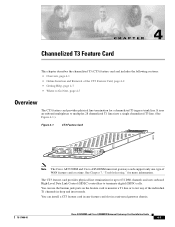
... individual T1 channels in drop and insert mode. You can install a CT3 feature card in a universal gateway chassis. 78-17406-01 Cisco AS5350XM and Cisco AS5400XM Universal Gateways Card Installation Guide 4-1 The CT3 feature card provides physical line termination for more information. You can... DS0 channels and uses onboard High-Level Data Link Control (HDLC) controllers to multiplex 28 channelized T1 lines into a single channelized T3 line. (See Figure 4-1.) Figure 4-1 CT3 Feature Card 29029 Note The Cisco AS5350XM and Cisco AS5400XM universal gateways each support only one type...
... individual T1 channels in drop and insert mode. You can install a CT3 feature card in a universal gateway chassis. 78-17406-01 Cisco AS5350XM and Cisco AS5400XM Universal Gateways Card Installation Guide 4-1 The CT3 feature card provides physical line termination for more information. You can... DS0 channels and uses onboard High-Level Data Link Control (HDLC) controllers to multiplex 28 channelized T1 lines into a single channelized T3 line. (See Figure 4-1.) Figure 4-1 CT3 Feature Card 29029 Note The Cisco AS5350XM and Cisco AS5400XM universal gateways each support only one type...

Installation Guide
Page 46
... status of the termination process, use the show chassis slot Note These commands are active calls on the feature card after waiting for slot 0. Slot 0 is in (see the Cisco AS5350XM and Cisco AS5400XM Universal Gateways Software Configuration Guide. Removing the CT3 Feature Card To...or E1 Feature Card" section on page 3-6 for the CT3 feature card is executed on the Cisco AS5350XM Chassis 36006 Slot 0 Slot 2 Slot 1 Slot 3 Cisco AS5350XM and Cisco AS5400XM Universal Gateways Card Installation Guide 4-2 78-17406-01 Online Insertion and Removal of the CT3 Feature Card Chapter ...
... status of the termination process, use the show chassis slot Note These commands are active calls on the feature card after waiting for slot 0. Slot 0 is in (see the Cisco AS5350XM and Cisco AS5400XM Universal Gateways Software Configuration Guide. Removing the CT3 Feature Card To...or E1 Feature Card" section on page 3-6 for the CT3 feature card is executed on the Cisco AS5350XM Chassis 36006 Slot 0 Slot 2 Slot 1 Slot 3 Cisco AS5350XM and Cisco AS5400XM Universal Gateways Card Installation Guide 4-2 78-17406-01 Online Insertion and Removal of the CT3 Feature Card Chapter ...