Installation Guide
Page 4
... Switching Module (WS-X6516-GBIC) 1-26 Switch Fabric Module (WS-C6500-SFM) 1-27 Switch Fabric Module 2 (WS-X6500-SFM2) 1-27 Cisco Application Control Engine (ACE) Module (ACE10-6500-K9) 1-28 Catalyst 6000 Family Module LED Descriptions 1-29 SPA Interface Processors 1-29 7600-SIP-200...Line Cards 1-34 Cisco 7600 ES+ 4TG3C, -4TG3CXL Line Cards 1-34 Cisco 7600 ES+ 20G3C, -20G3CXL Line Cards 1-35 Cisco 7600 ES+ 40G3C, -40G3CXL Line Cards 1-36 Port Addresses 1-37 Physical Interface Addresses 1-37 MAC Addresses 1-38 Hot Swapping Supervisor Engines and Modules 1-39 Power Management and Environmental ...
... Switching Module (WS-X6516-GBIC) 1-26 Switch Fabric Module (WS-C6500-SFM) 1-27 Switch Fabric Module 2 (WS-X6500-SFM2) 1-27 Cisco Application Control Engine (ACE) Module (ACE10-6500-K9) 1-28 Catalyst 6000 Family Module LED Descriptions 1-29 SPA Interface Processors 1-29 7600-SIP-200...Line Cards 1-34 Cisco 7600 ES+ 4TG3C, -4TG3CXL Line Cards 1-34 Cisco 7600 ES+ 20G3C, -20G3CXL Line Cards 1-35 Cisco 7600 ES+ 40G3C, -40G3CXL Line Cards 1-36 Port Addresses 1-37 Physical Interface Addresses 1-37 MAC Addresses 1-38 Hot Swapping Supervisor Engines and Modules 1-39 Power Management and Environmental ...
Installation Guide
Page 17
... and Modules, page 1-39 • Power Management and Environmental Monitoring, page 1-39 • OSM Technology Overview, page 1-39 Cisco 7600 Series Routers The Cisco 7600 series routers consist of these routers: • Cisco 7603 router (3 slots) • Cisco 7604 router (4 slots) • Cisco 7606 router (6 slots) • Cisco 7609 router (9 vertical slots) • Cisco 7609-S router (9 vertical slots) •...
... and Modules, page 1-39 • Power Management and Environmental Monitoring, page 1-39 • OSM Technology Overview, page 1-39 Cisco 7600 Series Routers The Cisco 7600 series routers consist of these routers: • Cisco 7603 router (3 slots) • Cisco 7604 router (4 slots) • Cisco 7606 router (6 slots) • Cisco 7609 router (9 vertical slots) • Cisco 7609-S router (9 vertical slots) •...
Installation Guide
Page 18
...redundant supervisor engine must be installed in slot 6. - Cisco 7600 Series Routers Chapter 1 Product Overview • A supervisor engine with two modular Gigabit interface uplinks and an optional redundant supervisor engine, in one of the Cisco 7613 router. Supervisor Engine 2, Policy Feature Card 2 (... and MSFC3 - Twelve additional modules for the Cisco 7613 router • Hot-swappable fan assembly, redundant AC-input or DC-input power supplies, and modules • Redundant AC-input or DC-input power entry modules (PEMs) (Cisco 7603 and 7606 routers only) • Backplane that...
...redundant supervisor engine must be installed in slot 6. - Cisco 7600 Series Routers Chapter 1 Product Overview • A supervisor engine with two modular Gigabit interface uplinks and an optional redundant supervisor engine, in one of the Cisco 7613 router. Supervisor Engine 2, Policy Feature Card 2 (... and MSFC3 - Twelve additional modules for the Cisco 7613 router • Hot-swappable fan assembly, redundant AC-input or DC-input power supplies, and modules • Redundant AC-input or DC-input power entry modules (PEMs) (Cisco 7603 and 7606 routers only) • Backplane that...
Installation Guide
Page 19
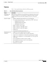
...Description Refer to the Cisco 7600 Series Cisco IOS Software Configuration Guide, 12.1E or the Cisco 7600 Series Cisco IOS Software Configuration Guide, 12.2SX for detailed information about the features supported on the Cisco 7600 series routers. • Modular, upgradable feature modules ...DC-input PEMs (Cisco 7603 and 7606 routers only) • Power management for modules and power supplies • Environmental monitoring of the Cisco 7600 series router. or DC-input, load-sharing power supplies • Support for two redundant AC- Chapter 1 Product Overview Cisco 7600 Series Routers...
...Description Refer to the Cisco 7600 Series Cisco IOS Software Configuration Guide, 12.1E or the Cisco 7600 Series Cisco IOS Software Configuration Guide, 12.2SX for detailed information about the features supported on the Cisco 7600 series routers. • Modular, upgradable feature modules ...DC-input PEMs (Cisco 7603 and 7606 routers only) • Power management for modules and power supplies • Environmental monitoring of the Cisco 7600 series router. or DC-input, load-sharing power supplies • Support for two redundant AC- Chapter 1 Product Overview Cisco 7600 Series Routers...
Installation Guide
Page 20
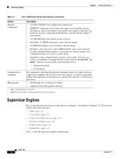
... redundant supervisor engine and fans) support hot swapping, which allows you to add, replace, or remove components without interrupting the system power or causing other details unique to each module. • 256-MB DRAM for the default system software. • Bootflash-32-...the file system (such as cd, pwd, dir, and delete). Book Title 1-4 OL-5077-7 Supervisor Engines Chapter 1 Product Overview Table 1-1 Cisco 7600 Series Router Key Features (continued) Feature Description Memory components • 512-KB NVRAM stores configuration information. • EEPROM2 component on the ...
... redundant supervisor engine and fans) support hot swapping, which allows you to add, replace, or remove components without interrupting the system power or causing other details unique to each module. • 256-MB DRAM for the default system software. • Bootflash-32-...the file system (such as cd, pwd, dir, and delete). Book Title 1-4 OL-5077-7 Supervisor Engines Chapter 1 Product Overview Table 1-1 Cisco 7600 Series Router Key Features (continued) Feature Description Memory components • 512-KB NVRAM stores configuration information. • EEPROM2 component on the ...
Installation Guide
Page 23
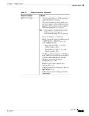
... 720-Gbps switch fabric • PFC3C and MSFC4 with 512-MB bootflash, 4-MB NVRAM, 4-MB ROMmon, and several DRAM options: - to 1 GB) • Requires larger power supplies and a high-speed fan tray • QoS port architecture, 10GE ports (Rx/Tx): 8q8t/1p7q8t (CoS) • QoS port architecture, 1GE ports (Rx/Tx...
... 720-Gbps switch fabric • PFC3C and MSFC4 with 512-MB bootflash, 4-MB NVRAM, 4-MB ROMmon, and several DRAM options: - to 1 GB) • Requires larger power supplies and a high-speed fan tray • QoS port architecture, 10GE ports (Rx/Tx): 8q8t/1p7q8t (CoS) • QoS port architecture, 1GE ports (Rx/Tx...
Installation Guide
Page 24
Switch processor (SP): 1- to 1 GB) • Requires larger power supplies and a high-speed fan tray • QoS port architecture, 10GE ports (Rx/Tx): 8q8t/1p7q8t (CoS) • QoS port architecture, 1GE ports (Rx/Tx): ...
Switch processor (SP): 1- to 1 GB) • Requires larger power supplies and a high-speed fan tray • QoS port architecture, 10GE ports (Rx/Tx): 8q8t/1p7q8t (CoS) • QoS port architecture, 1GE ports (Rx/Tx): ...
Installation Guide
Page 25
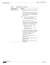
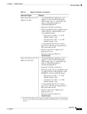
... 1 GB) • 2 CompactFlash Type II slots (on front panel) and 2-GB internal CompactFlash (1 GB each for information see http://www.cisco.com/univercd/cc/td/doc/product/core/cis7600/hardware/cis_76xx/remrep.htm #1098824. Chapter 1 Product Overview Supervisor Engines Table 1-2 Supervisor Engines (continued) ...form pluggable (SFP) module; to 4-GB DRAM (default 1 GB) • Switch processor (SP): 1- for RP and SP) • Requires larger power supplies and a high-speed fan tray • QoS port architecture (Rx/Tx) is configurable with either a 1-Gbps SFP module or a 10/100/1000...
... 1 GB) • 2 CompactFlash Type II slots (on front panel) and 2-GB internal CompactFlash (1 GB each for information see http://www.cisco.com/univercd/cc/td/doc/product/core/cis7600/hardware/cis_76xx/remrep.htm #1098824. Chapter 1 Product Overview Supervisor Engines Table 1-2 Supervisor Engines (continued) ...form pluggable (SFP) module; to 4-GB DRAM (default 1 GB) • Switch processor (SP): 1- for RP and SP) • Requires larger power supplies and a high-speed fan tray • QoS port architecture (Rx/Tx) is configurable with either a 1-Gbps SFP module or a 10/100/1000...
Installation Guide
Page 27
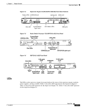
... uplink ports 10GE UPLINK 4 5 LINK LINK LINK LEDs 250253 The LEDs on the supervisor engine front panel indicate the status of the supervisor engine, modules, power supplies, and fan assembly. OL-5077-7 Book Title 1-11 Table 1-3 describes LED operation for the Supervisor Engine 720. Table 1-5 describes LED operation for the Supervisor...
... uplink ports 10GE UPLINK 4 5 LINK LINK LINK LEDs 250253 The LEDs on the supervisor engine front panel indicate the status of the supervisor engine, modules, power supplies, and fan assembly. OL-5077-7 Book Title 1-11 Table 1-3 describes LED operation for the Supervisor Engine 720. Table 1-5 describes LED operation for the Supervisor...

Installation Guide
Page 28
... module temperature major threshold has been exceeded.3 The temperature of the supervisor engine major threshold has been exceeded. Orange Sufficient power is not available for all modules. orange Off No signal is operational and active. The VTT module terminates signals on... is detected. 1. Orange The link has been disabled by software. Orange The module is operational. Orange The power supply or power supply fan failed. Incompatible power supplies are reporting OK. Flashing The link is available for all modules. VTT = voltage termination module. Supervisor ...
... module temperature major threshold has been exceeded.3 The temperature of the supervisor engine major threshold has been exceeded. Orange Sufficient power is not available for all modules. orange Off No signal is operational and active. The VTT module terminates signals on... is detected. 1. Orange The link has been disabled by software. Orange The module is operational. Orange The power supply or power supply fan failed. Incompatible power supplies are reporting OK. Flashing The link is available for all modules. VTT = voltage termination module. Supervisor ...

Installation Guide
Page 29
... major threshold has been exceeded. Blinking Continuous backplane stall. Red ACTIVE Green The module is operational (normal initialization sequence). Sufficient power is operational. LINK Green The port is available for all modules. DISK 1 Green The disk is active. The SYSTEM and... PWR MGMT LED indications on a redundant supervisor engine are reporting OK. Orange The module is powering up or a minor hardware fault has occurred. Yellow Minor hardware problems. SYSTEM1 Red Green An overtemperature condition has occurred. (A major...
... major threshold has been exceeded. Blinking Continuous backplane stall. Red ACTIVE Green The module is operational (normal initialization sequence). Sufficient power is operational. LINK Green The port is available for all modules. DISK 1 Green The disk is active. The SYSTEM and... PWR MGMT LED indications on a redundant supervisor engine are reporting OK. Orange The module is powering up or a minor hardware fault has occurred. Yellow Minor hardware problems. SYSTEM1 Red Green An overtemperature condition has occurred. (A major...

Installation Guide
Page 30
...The disk is booting or running diagnostics (normal initialization sequence). The module is active. 1. Red Major hardware problem. Sufficient power is powering up or has minor hardware problems. Red Major hardware problem. Orange The module is available for all modules. Orange The ...) LED SYSTEM1 Color Green Description All chassis environmental monitors are reporting OK. Blinking Continuous backplane stall. Flashing The port is powering up or a minor hardware fault has occurred. The SYSTEM and PWR MGMT LED indications on a redundant supervisor engine are synchronized...
...The disk is booting or running diagnostics (normal initialization sequence). The module is active. 1. Red Major hardware problem. Sufficient power is powering up or has minor hardware problems. Red Major hardware problem. Orange The module is available for all modules. Orange The ...) LED SYSTEM1 Color Green Description All chassis environmental monitors are reporting OK. Blinking Continuous backplane stall. Flashing The port is powering up or a minor hardware fault has occurred. The SYSTEM and PWR MGMT LED indications on a redundant supervisor engine are synchronized...

Installation Guide
Page 31
...Button The Reset button allows you to connect a terminal to access the system either the console cable and adapters provided with the Cisco 7600 series routers or the console cable provided with a modem). Note EIA/TIA-232 and EIA/TIA-449 were known as recommended...Chapter 1 Product Overview Supervisor Engines Table 1-6 Route Switch Processor 720 LEDs (continued) LED Color Description PWR MGMT1 Orange Green The module is powering up or has minor hardware problems. Red Major hardware problem. The SYSTEM and PWR MGMT LED indications on a redundant supervisor engine are ...
...Button The Reset button allows you to connect a terminal to access the system either the console cable and adapters provided with the Cisco 7600 series routers or the console cable provided with a modem). Note EIA/TIA-232 and EIA/TIA-449 were known as recommended...Chapter 1 Product Overview Supervisor Engines Table 1-6 Route Switch Processor 720 LEDs (continued) LED Color Description PWR MGMT1 Orange Green The module is powering up or has minor hardware problems. Red Major hardware problem. The SYSTEM and PWR MGMT LED indications on a redundant supervisor engine are ...

Installation Guide
Page 37
...STATUS LED on or module has been hot inserted). the module does not come online. Module is operational. Module is not receiving power. OL-5077-7 Book Title 1-21 Figure 1-17 OSM STATUS and LINK LEDs-Gigabit Ethernet Ports OSM-4OC12-POS-MM 1 STATUS 2... OSM STATUS LED Description LED STATUS Normal initialization sequence Fault during the initial reset; module is resetting (system has just been powered on all port-specific tests fail; All diagnostics pass; The module fails to successfully download code and configuration information during initialization sequence...
...STATUS LED on or module has been hot inserted). the module does not come online. Module is operational. Module is not receiving power. OL-5077-7 Book Title 1-21 Figure 1-17 OSM STATUS and LINK LEDs-Gigabit Ethernet Ports OSM-4OC12-POS-MM 1 STATUS 2... OSM STATUS LED Description LED STATUS Normal initialization sequence Fault during the initial reset; module is resetting (system has just been powered on all port-specific tests fail; All diagnostics pass; The module fails to successfully download code and configuration information during initialization sequence...
Installation Guide
Page 45
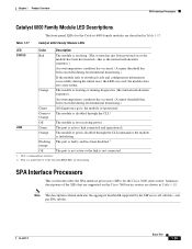
...LED Color Description STATUS Red The module is resetting. (The system has just been powered on the Cisco 7600 series routers are functioning. Orange The module is not receiving power. Chapter 1 Product Overview SPA Interface Processors Catalyst 6000 Family Module LED Descriptions The ...front-panel LEDs for the Cisco 7600 series router. the module does not come online. The module is...
...LED Color Description STATUS Red The module is resetting. (The system has just been powered on the Cisco 7600 series routers are functioning. Orange The module is not receiving power. Chapter 1 Product Overview SPA Interface Processors Catalyst 6000 Family Module LED Descriptions The ...front-panel LEDs for the Cisco 7600 series router. the module does not come online. The module is...

Installation Guide
Page 48
...OL-5077-7 The line card is not a valid Ethernet link. The port is one Status LED and two A/L (Active Loopback) LEDs. Figure 1-31 Cisco 7600-ES20-10G Faceplate 7600-ES20-10G3CXL 1 0 ETHERNET SERVICES MODULE CLASS 1 LASER There is enabled and a valid Ethernet link has been established. There...online. Table 1-21 provides LED descriptions. The line card is one line card Status LED and two port Status LEDs. The port is powered off. Table 1-21 provides LED descriptions. The line card is not enabled by software. Ethernet Services 20G Line Cards Chapter 1 Product Overview ...
...OL-5077-7 The line card is not a valid Ethernet link. The port is one Status LED and two A/L (Active Loopback) LEDs. Figure 1-31 Cisco 7600-ES20-10G Faceplate 7600-ES20-10G3CXL 1 0 ETHERNET SERVICES MODULE CLASS 1 LASER There is enabled and a valid Ethernet link has been established. There...online. Table 1-21 provides LED descriptions. The line card is one line card Status LED and two port Status LEDs. The port is powered off. Table 1-21 provides LED descriptions. The line card is not enabled by software. Ethernet Services 20G Line Cards Chapter 1 Product Overview ...

Installation Guide
Page 49
... Ethernet Services Plus Line Cards 7600-ES20-GE The Cisco 7600-ES20-GE line card has 21 LEDs, as available. The port is enabled but there is enabled and a valid Ethernet link has been established. The port is powered off. The line card is not enabled by software. Undefined ...condition. The SFP and XFP modules allow the line cards to be configured for the Cisco 7600 series routers that are the link interface daughter cards that accept...
... Ethernet Services Plus Line Cards 7600-ES20-GE The Cisco 7600-ES20-GE line card has 21 LEDs, as available. The port is enabled but there is enabled and a valid Ethernet link has been established. The port is powered off. The line card is not enabled by software. Undefined ...condition. The SFP and XFP modules allow the line cards to be configured for the Cisco 7600 series routers that are the link interface daughter cards that accept...

Installation Guide
Page 50
... shown in Figure 1-35 and Figure 1-36. The line card is one Status LED and two A/L (Active Loopback) LEDs. Table 1-23 Cisco 7600 ES+ 2TG3C, -3CXL LEDs LED Label STATUS A/L Color Red Green Yellow Off Amber State On On On Off On Green On Green ... ETHERNET SERVICES MODULE 1 A/L CLASS 1 LASER 270819 Figure 1-34 Cisco 7600 ES+ 2TG3CXL Faceplate 270820 2 A/L 1 A/L 7600-ES+2TG3CXL EXT CLK STATUS ETHERNET SERVICES MODULE CLASS 1 LASER There is loading. Table 1-23 provides LED descriptions. There is powered off. Table 1-23 provides LED descriptions. The line card is ...
... shown in Figure 1-35 and Figure 1-36. The line card is one Status LED and two A/L (Active Loopback) LEDs. Table 1-23 Cisco 7600 ES+ 2TG3C, -3CXL LEDs LED Label STATUS A/L Color Red Green Yellow Off Amber State On On On Off On Green On Green ... ETHERNET SERVICES MODULE 1 A/L CLASS 1 LASER 270819 Figure 1-34 Cisco 7600 ES+ 2TG3CXL Faceplate 270820 2 A/L 1 A/L 7600-ES+2TG3CXL EXT CLK STATUS ETHERNET SERVICES MODULE CLASS 1 LASER There is loading. Table 1-23 provides LED descriptions. There is powered off. Table 1-23 provides LED descriptions. The line card is ...

Installation Guide
Page 51
... The line card is not enabled by software. The port is powered off. The line card is enabled and a valid Ethernet link has been established. The port is online. Undefined condition. The line card is not a valid Ethernet link. Table 1-24 Cisco 7600 ES+ 4TG3C, -4TG3CXL LEDs LED Label STATUS A/L Color Red...
... The line card is not enabled by software. The port is powered off. The line card is enabled and a valid Ethernet link has been established. The port is online. Undefined condition. The line card is not a valid Ethernet link. Table 1-24 Cisco 7600 ES+ 4TG3C, -4TG3CXL LEDs LED Label STATUS A/L Color Red...

Installation Guide
Page 52
..., as shown in Figure 1-39 and Figure 1-40. Undefined condition. The port is powered off. Figure 1-39 Cisco 7600 ES+ 40G3C Line Card Faceplate 39 37 35 33 31 11 13 15 17 ... 9 CLASS 1 LASER 12 14 16 18 20 A/L 22 24 26 28 30 40 38 36 34 32 270821 Figure 1-40 Cisco 7600 ES+ 40G3CXL Line Card Faceplate 7600-ES+40G3CXL 39 37 35 33 31 11 13 15 17 19 A/L 21 23 25 ... 6 4 2 There is one line card STATUS LED and twenty A/L (Active Loopback) LEDs. Table 1-25 Cisco 7600 ES+ 20G3C, -20G3CXL Line Card LEDs LED Label STATUS A/L Color Red Green Yellow Off Amber State On ...
..., as shown in Figure 1-39 and Figure 1-40. Undefined condition. The port is powered off. Figure 1-39 Cisco 7600 ES+ 40G3C Line Card Faceplate 39 37 35 33 31 11 13 15 17 ... 9 CLASS 1 LASER 12 14 16 18 20 A/L 22 24 26 28 30 40 38 36 34 32 270821 Figure 1-40 Cisco 7600 ES+ 40G3CXL Line Card Faceplate 7600-ES+40G3CXL 39 37 35 33 31 11 13 15 17 19 A/L 21 23 25 ... 6 4 2 There is one line card STATUS LED and twenty A/L (Active Loopback) LEDs. Table 1-25 Cisco 7600 ES+ 20G3C, -20G3CXL Line Card LEDs LED Label STATUS A/L Color Red Green Yellow Off Amber State On ...


