Installation Guide
Page 18
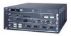
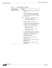
... additional modules for the Cisco 7613 router • Hot-swappable fan assembly, redundant AC-input or DC-input power supplies, and modules • Redundant AC-input or DC-input power entry modules (PEMs) (Cisco 7603 and 7606 routers only)... • Backplane that is not supported on the redundant supervisor engine in standby mode. • Additional OSMs, recommended Catalyst 6000 family modules, and SIPs in any combination: - Cisco 7600 Series Routers Chapter 1 Product Overview • A supervisor engine with two modular...
... additional modules for the Cisco 7613 router • Hot-swappable fan assembly, redundant AC-input or DC-input power supplies, and modules • Redundant AC-input or DC-input power entry modules (PEMs) (Cisco 7603 and 7606 routers only)... • Backplane that is not supported on the redundant supervisor engine in standby mode. • Additional OSMs, recommended Catalyst 6000 family modules, and SIPs in any combination: - Cisco 7600 Series Routers Chapter 1 Product Overview • A supervisor engine with two modular...
Installation Guide
Page 19
... Refer to the Cisco 7600 Series Cisco IOS Software Configuration Guide, 12.1E or the Cisco 7600 Series Cisco IOS Software Configuration Guide, 12.2SX for detailed information about the features supported on the Cisco 7600 series routers. • Modular, upgradable feature modules... and power supplies • Environmental monitoring of the Cisco 7600 series router. or DC-input PEMs (Cisco 7603 and 7606 routers only) • Power management for two redundant AC- or DC-input, load-sharing power supplies • Support for two redundant AC- Chapter 1 Product Overview Cisco 7600 ...
... Refer to the Cisco 7600 Series Cisco IOS Software Configuration Guide, 12.1E or the Cisco 7600 Series Cisco IOS Software Configuration Guide, 12.2SX for detailed information about the features supported on the Cisco 7600 series routers. • Modular, upgradable feature modules... and power supplies • Environmental monitoring of the Cisco 7600 series router. or DC-input PEMs (Cisco 7603 and 7606 routers only) • Power management for two redundant AC- or DC-input, load-sharing power supplies • Support for two redundant AC- Chapter 1 Product Overview Cisco 7600 ...
Installation Guide
Page 23
... CompactFlash (512 KB each internal CompactFlash to 4-GB DRAM (default 1 GB) - you can optionally increase each for RP and SP; to 1 GB) • Requires larger power supplies and a high-speed fan tray • QoS port architecture, 10GE ports (Rx/Tx): 8q8t/1p7q8t (CoS) • QoS port architecture, 1GE ports (Rx/Tx): 2q8t...
... CompactFlash (512 KB each internal CompactFlash to 4-GB DRAM (default 1 GB) - you can optionally increase each for RP and SP; to 1 GB) • Requires larger power supplies and a high-speed fan tray • QoS port architecture, 10GE ports (Rx/Tx): 8q8t/1p7q8t (CoS) • QoS port architecture, 1GE ports (Rx/Tx): 2q8t...
Installation Guide
Page 24
...) • One CompactFlash Type II slot (512 KB) on front panel and two internal CompactFlash (512 KB each internal CompactFlash to 1 GB) • Requires larger power supplies and a high-speed fan tray • QoS port architecture, 10GE ports (Rx/Tx): 8q8t/1p7q8t (CoS) • QoS port architecture, 1GE ports (Rx/Tx): 2q8t...
...) • One CompactFlash Type II slot (512 KB) on front panel and two internal CompactFlash (512 KB each internal CompactFlash to 1 GB) • Requires larger power supplies and a high-speed fan tray • QoS port architecture, 10GE ports (Rx/Tx): 8q8t/1p7q8t (CoS) • QoS port architecture, 1GE ports (Rx/Tx): 2q8t...
Installation Guide
Page 25
...and 2-GB internal CompactFlash (1 GB each for information see http://www.cisco.com/univercd/cc/td/doc/product/core/cis7600/hardware/cis_76xx/remrep.htm #1098824. for RP and SP) • Requires larger power supplies and a high-speed fan tray • QoS port architecture (Rx/... • 2 CompactFlash Type II slots (on front panel) and 2-GB internal CompactFlash (1 GB each for RP and SP) • Requires larger power supplies and a high-speed fan tray • QoS port architecture (Rx/Tx) is 1p1q4t/1p2q2t 1. Chapter 1 Product Overview Supervisor Engines Table 1-2 Supervisor ...
...and 2-GB internal CompactFlash (1 GB each for information see http://www.cisco.com/univercd/cc/td/doc/product/core/cis7600/hardware/cis_76xx/remrep.htm #1098824. for RP and SP) • Requires larger power supplies and a high-speed fan tray • QoS port architecture (Rx/... • 2 CompactFlash Type II slots (on front panel) and 2-GB internal CompactFlash (1 GB each for RP and SP) • Requires larger power supplies and a high-speed fan tray • QoS port architecture (Rx/Tx) is 1p1q4t/1p2q2t 1. Chapter 1 Product Overview Supervisor Engines Table 1-2 Supervisor ...
Installation Guide
Page 27
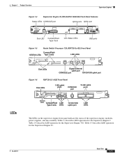
... uplink ports 10GE UPLINK 4 5 LINK LINK LINK LEDs 250253 The LEDs on the supervisor engine front panel indicate the status of the supervisor engine, modules, power supplies, and fan assembly. Table 1-4 describes LED operation for the Supervisor Engine 720.
... uplink ports 10GE UPLINK 4 5 LINK LINK LINK LEDs 250253 The LEDs on the supervisor engine front panel indicate the status of the supervisor engine, modules, power supplies, and fan assembly. Table 1-4 describes LED operation for the Supervisor Engine 720.

Installation Guide
Page 28
... The port is detected. 1. orange Off No signal is operational. If no PCMCIA card is not available for all modules. Incompatible power supplies are reporting OK. ACTIVE Green The supervisor engine is operational, the switch load meter indicates (as an approximate percentage) the current traffic...is in the slot and goes off when you insert a card. Orange The link has been disabled by software. Orange The power supply or power supply fan failed. PWR MGMT1 Orange Green The supervisor engine is operational (normal initialization sequence). Orange The module is bad and has ...
... The port is detected. 1. orange Off No signal is operational. If no PCMCIA card is not available for all modules. Incompatible power supplies are reporting OK. ACTIVE Green The supervisor engine is operational, the switch load meter indicates (as an approximate percentage) the current traffic...is in the slot and goes off when you insert a card. Orange The link has been disabled by software. Orange The power supply or power supply fan failed. PWR MGMT1 Orange Green The supervisor engine is operational (normal initialization sequence). Orange The module is bad and has ...
Installation Guide
Page 84
...) FAN OUTPUT OK FAIL INPUT OK connection ESD ground strap FAN OUTPUT OK FAIL o o SELECT STATUS ACTIVE NEXT Power supply 1 INPUT OK SELECT STATUS ACTIVE NEXT Slot Numbers on Cisco 7609 Router and Cisco 7609-S Router WS-X6K-SUP2-2GE STATUSSYSTEMCONSOLPEWR MGRMETSET CONSOLE SUPERVISOR2 CONSOLE PORT MODE PCMCIA EJECT LINK Switch Load 100% 1% PORT...
...) FAN OUTPUT OK FAIL INPUT OK connection ESD ground strap FAN OUTPUT OK FAIL o o SELECT STATUS ACTIVE NEXT Power supply 1 INPUT OK SELECT STATUS ACTIVE NEXT Slot Numbers on Cisco 7609 Router and Cisco 7609-S Router WS-X6K-SUP2-2GE STATUSSYSTEMCONSOLPEWR MGRMETSET CONSOLE SUPERVISOR2 CONSOLE PORT MODE PCMCIA EJECT LINK Switch Load 100% 1% PORT...
Installation Guide
Page 85
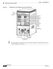
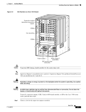
... series router, perform these steps: Step 1 Choose a slot for the supervisor engine or module. Warning Hazardous voltage or energy is present on Cisco 7613 Router Installing a Supervisor Engine or a Module Supervisor engine Redundant supervisor engine OSMs Fan assembly OSMs 1 2 3 4 5 6 7 8 9 ...PORT 3 ACTIVE TX CAARLRAIERRM RX RX TX NEXT 13 91093 o o INPUT OK FAN OUTPUT OK FAIL INPUT OK FAN OUTPUT OK FAIL Power supply 1 Power supply 2 (redundant) ESD ground strap connection Caution To prevent ESD damage, handle modules by the carrier edges only. To install a supervisor ...
... series router, perform these steps: Step 1 Choose a slot for the supervisor engine or module. Warning Hazardous voltage or energy is present on Cisco 7613 Router Installing a Supervisor Engine or a Module Supervisor engine Redundant supervisor engine OSMs Fan assembly OSMs 1 2 3 4 5 6 7 8 9 ...PORT 3 ACTIVE TX CAARLRAIERRM RX RX TX NEXT 13 91093 o o INPUT OK FAN OUTPUT OK FAIL INPUT OK FAN OUTPUT OK FAIL Power supply 1 Power supply 2 (redundant) ESD ground strap connection Caution To prevent ESD damage, handle modules by the carrier edges only. To install a supervisor ...

Installation Guide
Page 102
...the LEDs on the processor modules are on , there might be a problem with the blower or the +24 V DC power: - Ensure that the power source, power cable, and power supply are faulty. 4. If the blower is inserted completely in the backplane sockets. 2. Troubleshooting Router Booting Issues Chapter 4 Troubleshooting... power switch is on . Ensure that the blower module is seated properly. If the blower and LEDs are on position. 3. Check whether or not the blower is probably faulty. 2. Check whether or not the blower is operating when you must replace the blower module. Cisco ...
...the LEDs on the processor modules are on , there might be a problem with the blower or the +24 V DC power: - Ensure that the power source, power cable, and power supply are faulty. 4. If the blower is inserted completely in the backplane sockets. 2. Troubleshooting Router Booting Issues Chapter 4 Troubleshooting... power switch is on . Ensure that the blower module is seated properly. If the blower and LEDs are on position. 3. Check whether or not the blower is probably faulty. 2. Check whether or not the blower is operating when you must replace the blower module. Cisco ...
Installation Guide
Page 103
...down . Check the seating of -tolerance power condition, the Output Fail LED goes on an individual interface processor is operational. 5. Check to see this message at startup, it will hang the system. 1. supervisor = Route Switch Processor OL-5077-7 Cisco 7600 Series Routers Module Guide 4-3 If ... LEDs. If the supervisor Link LED is not seated properly, it means that the power supplies and blower are not seated properly, they will hang the system. 3. This LED should be powered on each interface processor. This shutdown message might have slipped away from an out-of...
...down . Check the seating of -tolerance power condition, the Output Fail LED goes on an individual interface processor is operational. 5. Check to see this message at startup, it will hang the system. 1. supervisor = Route Switch Processor OL-5077-7 Cisco 7600 Series Routers Module Guide 4-3 If ... LEDs. If the supervisor Link LED is not seated properly, it means that the power supplies and blower are not seated properly, they will hang the system. 3. This LED should be powered on each interface processor. This shutdown message might have slipped away from an out-of...


