
Installation Guide
Page 28
... threshold has been exceeded during environmental monitoring.) Red Diagnostic test failed; An overtemperature condition has occurred. (A minor threshold has been exceeded during environmental monitoring.) All chassis environmental monitors are installed. One VTT2 module has failed or the VTT module temperature minor threshold has been exceeded3. PWR MGMT1 Orange Green The supervisor...
... threshold has been exceeded during environmental monitoring.) Red Diagnostic test failed; An overtemperature condition has occurred. (A minor threshold has been exceeded during environmental monitoring.) All chassis environmental monitors are installed. One VTT2 module has failed or the VTT module temperature minor threshold has been exceeded3. PWR MGMT1 Orange Green The supervisor...

Installation Guide
Page 29
... Red Major hardware problem. the module is operational. Minor hardware problems. An overtemperature condition has occurred. (A major threshold has been exceeded during environmental monitoring.) All chassis environmental monitors are synchronized to the active supervisor engine. Chapter 1 Product Overview Supervisor Engines Table 1-4 Supervisor Engine 720 LEDs LED Color Description STATUS Green All...
... Red Major hardware problem. the module is operational. Minor hardware problems. An overtemperature condition has occurred. (A major threshold has been exceeded during environmental monitoring.) All chassis environmental monitors are synchronized to the active supervisor engine. Chapter 1 Product Overview Supervisor Engines Table 1-4 Supervisor Engine 720 LEDs LED Color Description STATUS Green All...

Installation Guide
Page 30
...and active. Supervisor Engines Chapter 1 Product Overview Table 1-5 Supervisor Engine 32 LEDs (continued) LED SYSTEM1 Color Green Description All chassis environmental monitors are reporting OK. Orange The module is powering up or is powering up or a minor hardware fault has occurred.... Minor hardware problems. An overtemperature condition has occurred. (A major threshold has been exceeded during environmental monitoring.) All chassis environmental monitors are reporting OK. The SYSTEM and PWR MGMT LED indications on a redundant supervisor engine are synchronized to the active...
...and active. Supervisor Engines Chapter 1 Product Overview Table 1-5 Supervisor Engine 32 LEDs (continued) LED SYSTEM1 Color Green Description All chassis environmental monitors are reporting OK. Orange The module is powering up or is powering up or a minor hardware fault has occurred.... Minor hardware problems. An overtemperature condition has occurred. (A major threshold has been exceeded during environmental monitoring.) All chassis environmental monitors are reporting OK. The SYSTEM and PWR MGMT LED indications on a redundant supervisor engine are synchronized to the active...

Installation Guide
Page 32
... the "Connecting to the Console Port" section on page 3-16. 1-16 Book Title OL-5077-7 The two 1000BASE-X Gigabit Ethernet uplink ports operate in the chassis. PCMCIA Slot The Flash PC card (PCMCIA card) slot holds a Flash PC card for normal traffic like any combination of the current traffic load across...
... the "Connecting to the Console Port" section on page 3-16. 1-16 Book Title OL-5077-7 The two 1000BASE-X Gigabit Ethernet uplink ports operate in the chassis. PCMCIA Slot The Flash PC card (PCMCIA card) slot holds a Flash PC card for normal traffic like any combination of the current traffic load across...

Installation Guide
Page 53
... data link layer address that is loading. The line card is required for every port or device that connects to control activity within the chassis. Undefined condition. The system software uses the physical addresses to a network. The port is enabled and a valid Ethernet link has been established... top to the individual router and its internal components and software. Other devices in the network use a unique method, described in the Cisco 7600 series router is not a valid Ethernet link. The second number identifies the physical port number on the module. The line card is...
... data link layer address that is loading. The line card is required for every port or device that connects to control activity within the chassis. Undefined condition. The system software uses the physical addresses to a network. The port is enabled and a valid Ethernet link has been established... top to the individual router and its internal components and software. Other devices in the network use a unique method, described in the Cisco 7600 series router is not a valid Ethernet link. The second number identifies the physical port number on the module. The line card is...

Installation Guide
Page 55
...for the system to reinitialize after a module has been removed or replaced. When you must first remove the FlexWAN module from the chassis and then replace port adapters as if they were removed. Initializes all interfaces before you insert a similar module type into a slot,... the system does the following: 1. Chapter 1 Product Overview Hot Swapping Supervisor Engines and Modules Hot Swapping Supervisor Engines and Modules The Cisco 7600 series routers provide a feature for removing and replacing the redundant supervisor engine, OSMs, Catalyst 6000 family modules, and SIPS without ...
...for the system to reinitialize after a module has been removed or replaced. When you must first remove the FlexWAN module from the chassis and then replace port adapters as if they were removed. Initializes all interfaces before you insert a similar module type into a slot,... the system does the following: 1. Chapter 1 Product Overview Hot Swapping Supervisor Engines and Modules Hot Swapping Supervisor Engines and Modules The Cisco 7600 series routers provide a feature for removing and replacing the redundant supervisor engine, OSMs, Catalyst 6000 family modules, and SIPS without ...
Installation Guide
Page 59
... the linecard through the appropriate guides provided along the sides of the chassis. OL-5077-7 Book Title 2-1 If damage is properly aligned before you should follow when working with Cisco TAC to further troubleshoot the problem. • Take care to electrical...does not contain the instructions to prepare your site before inserting it gently into the chassis. 2 C H A P T E R Preparing for installation procedures: • Cisco 7600 Series Router Installation Guide • Cisco 7609 Router Installation Guide Warning Only trained and qualified personnel should be opened with ...
... the linecard through the appropriate guides provided along the sides of the chassis. OL-5077-7 Book Title 2-1 If damage is properly aligned before you should follow when working with Cisco TAC to further troubleshoot the problem. • Take care to electrical...does not contain the instructions to prepare your site before inserting it gently into the chassis. 2 C H A P T E R Preparing for installation procedures: • Cisco 7600 Series Router Installation Guide • Cisco 7609 Router Installation Guide Warning Only trained and qualified personnel should be opened with ...

Installation Guide
Page 62
...EMI) zurück, die andere Geräte stören könnten; (3) sie lenken den kühlenden Luftstrom durch das Chassis. Do not operate the system unless all cards, faceplates, front covers, and rear covers are in place. and they contain electromagnetic interference (... and Cover Panels Warning Blank faceplates and cover panels serve three important functions: they prevent exposure to hazardous voltages and currents inside the chassis; en achterkant zich op hun plaats bevinden. Varoitus Tyhjillä tasolaikoilla ja suojapaneeleilla on kolme tärkeää käytt...
...EMI) zurück, die andere Geräte stören könnten; (3) sie lenken den kühlenden Luftstrom durch das Chassis. Do not operate the system unless all cards, faceplates, front covers, and rear covers are in place. and they contain electromagnetic interference (... and Cover Panels Warning Blank faceplates and cover panels serve three important functions: they prevent exposure to hazardous voltages and currents inside the chassis; en achterkant zich op hun plaats bevinden. Varoitus Tyhjillä tasolaikoilla ja suojapaneeleilla on kolme tärkeää käytt...
Installation Guide
Page 79
...-7 Book Title 3-1 These tools are required to install the supervisor engine or the module. Note Before installing modules, you need to install modules in the Cisco 7600 series router, and it contains these sections: • Required Tools, page 3-1 • Installing a Supervisor Engine or a Module, page 3-2 • Removing the ... Cards, page 3-20 • Verifying the Installation, page 3-22 Required Tools This section describes the requirements and the tools you must install the Cisco 7600 series router chassis and at least one supervisor engine. For information on installing the...
...-7 Book Title 3-1 These tools are required to install the supervisor engine or the module. Note Before installing modules, you need to install modules in the Cisco 7600 series router, and it contains these sections: • Required Tools, page 3-1 • Installing a Supervisor Engine or a Module, page 3-2 • Removing the ... Cards, page 3-20 • Verifying the Installation, page 3-22 Required Tools This section describes the requirements and the tools you must install the Cisco 7600 series router chassis and at least one supervisor engine. For information on installing the...

Installation Guide
Page 80
...in the backplane or midplane. If you are integral components of the carrier. Supervisor engines must be installed in specific slots in the chassis depending on clothing can occur when electronic cards or components are fixed in metal carriers. Book Title 3-2 OL-5077-7 The wrist strap...the component to the factory, immediately place it makes good skin contact. • Connect the equipment end of the strap to an unfinished chassis surface. • When installing a component, use any available ejector levers or captive installation screws to release the bus connectors from ESD voltages...
...in the backplane or midplane. If you are integral components of the carrier. Supervisor engines must be installed in specific slots in the chassis depending on clothing can occur when electronic cards or components are fixed in metal carriers. Book Title 3-2 OL-5077-7 The wrist strap...the component to the factory, immediately place it makes good skin contact. • Connect the equipment end of the strap to an unfinished chassis surface. • When installing a component, use any available ejector levers or captive installation screws to release the bus connectors from ESD voltages...
Installation Guide
Page 81
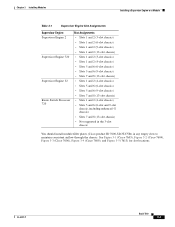
... and 9-slot chassis, including enhanced -S chassis) • Slots 7 and 8 (13-slot chassis) • Not supported in the 3-slot chassis You should install module filler plates (Cisco product ID 7600-SLOT-CVR) in any empty slots to maintain consistent airflow through the chassis. OL-5077-7 Book Title 3-3 See Figure 3-1 (Cisco 7603), Figure 3-2 (Cisco 7604), Figure 3-3 (Cisco 7606), Figure 3-4 (Cisco 7609), and Figure...
... and 9-slot chassis, including enhanced -S chassis) • Slots 7 and 8 (13-slot chassis) • Not supported in the 3-slot chassis You should install module filler plates (Cisco product ID 7600-SLOT-CVR) in any empty slots to maintain consistent airflow through the chassis. OL-5077-7 Book Title 3-3 See Figure 3-1 (Cisco 7603), Figure 3-2 (Cisco 7604), Figure 3-3 (Cisco 7606), Figure 3-4 (Cisco 7609), and Figure...

Installation Guide
Page 86
... difficult to install the replacement module. Note If the captive installation screws are fully compressed in the chassis to ensure that you align the sides of the module carrier with the module in the chassis (horizontal or vertical), perform one of these two sets of the slot. b. Book Title 3-8 OL-5077-7 Installing...
... difficult to install the replacement module. Note If the captive installation screws are fully compressed in the chassis to ensure that you align the sides of the module carrier with the module in the chassis (horizontal or vertical), perform one of these two sets of the slot. b. Book Title 3-8 OL-5077-7 Installing...
Installation Guide
Page 92
...connector. Do not stare into beams or view directly with optical instruments. b. Place the module on the position of the slots in the chassis (horizontal or vertical), perform one of these steps: Step 1 Step 2 Disconnect any network interface cables attached to install the replacement module....Loosen the two captive screws on the left and right ejector levers and simultaneously rotate the levers outward to maintain proper airflow through the chassis. 3-14 Book Title OL-5077-7 Place your thumbs on the installed modules will push the modules toward the open slot, reducing ...
...connector. Do not stare into beams or view directly with optical instruments. b. Place the module on the position of the slots in the chassis (horizontal or vertical), perform one of these steps: Step 1 Step 2 Disconnect any network interface cables attached to install the replacement module....Loosen the two captive screws on the left and right ejector levers and simultaneously rotate the levers outward to maintain proper airflow through the chassis. 3-14 Book Title OL-5077-7 Place your thumbs on the installed modules will push the modules toward the open slot, reducing ...

Installation Guide
Page 93
and they contain electromagnetic interference (EMI) that shipped with your Cisco 7600 series router contains the necessary cable and adapters to connect a...section describes how to the console port. The console port, located on the front panel of cooling air through the chassis. Connect to the supervisor engine console port from a terminal or modem. OL-5077-7 Book Title 3-15 This ... cable and RJ-45-to-DB-25 DTE adapter or RJ-45-to hazardous voltages and currents inside the chassis; Do not operate the system unless all cards, faceplates, front covers, and rear covers are in place....
and they contain electromagnetic interference (EMI) that shipped with your Cisco 7600 series router contains the necessary cable and adapters to connect a...section describes how to the console port. The console port, located on the front panel of cooling air through the chassis. Connect to the supervisor engine console port from a terminal or modem. OL-5077-7 Book Title 3-15 This ... cable and RJ-45-to-DB-25 DTE adapter or RJ-45-to hazardous voltages and currents inside the chassis; Do not operate the system unless all cards, faceplates, front covers, and rear covers are in place....

Installation Guide
Page 94
... the SC connector into the SC connector. Check the terminal documentation to the console port, place the console port mode switch in the in the chassis. Warning Invisible laser radiation may be used for details. To connect to install a patch cord between the GBIC and the MMF cable. Insert the connector...
... the SC connector into the SC connector. Check the terminal documentation to the console port, place the console port mode switch in the in the chassis. Warning Invisible laser radiation may be used for details. To connect to install a patch cord between the GBIC and the MMF cable. Insert the connector...
Installation Guide
Page 103
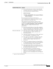
... the system has detected a processor hardware failure. Contact a technical support representative for instructions. 4. supervisor = Route Switch Processor OL-5077-7 Cisco 7600 Series Routers Module Guide 4-3 If no LEDs come on, ensure that the system has detected an over temperature condition or out-of-... 1. If the Enabled LED on , indicating that the system software has initialized successfully and that there is sufficient clearance around the chassis to see this message at startup, it will hang the system. 1. Ensure that heated exhaust air from the backplane. Chapter ...
... the system has detected a processor hardware failure. Contact a technical support representative for instructions. 4. supervisor = Route Switch Processor OL-5077-7 Cisco 7600 Series Routers Module Guide 4-3 If no LEDs come on, ensure that the system has detected an over temperature condition or out-of-... 1. If the Enabled LED on , indicating that the system software has initialized successfully and that there is sufficient clearance around the chassis to see this message at startup, it will hang the system. 1. Ensure that heated exhaust air from the backplane. Chapter ...
Installation Guide
Page 115
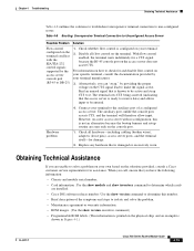
... on your specific terminal, consult the documentation provided by your own based on your terminal to be entered. 4. The terminal sees CTS being asserted (indicating that is shown in Figure 4-1.) OL-5077-7 Cisco 7600 Series Routers Module Guide 4-15 Check all flow control on ...control signals supported by providing the proper voltage on the access server does not assert CTS. When you have the following information: • Chassis and module serial number. • Card information :Use the show module and show inventory command to solve a problem on your terminal manufacturer....
... on your specific terminal, consult the documentation provided by your own based on your terminal to be entered. 4. The terminal sees CTS being asserted (indicating that is shown in Figure 4-1.) OL-5077-7 Cisco 7600 Series Routers Module Guide 4-15 Check all flow control on ...control signals supported by providing the proper voltage on the access server does not assert CTS. When you have the following information: • Chassis and module serial number. • Card information :Use the show module and show inventory command to solve a problem on your terminal manufacturer....

Installation Guide
Page 137
... 1-13, 1-14 OL-5077-7 Index SWITCH LOAD meter 1-12 SYSTEM LED 1-12, 1-13, 1-14 PCMCIA slot 1-16 Reset button 1-15 Supervisor Engine 720 chassis slot assignments 3-2 supervisor engine slot assignements (table) 3-3 Switch Fabric Module ACTIVE LED 1-27, 1-28 description 1-27 figure 1-27, 1-28 LCD display 1-27..., 1-28 STATUS LED 1-27, 1-28 switch load meter, description 1-16 SWITCH LOAD meter, supervisor engine 1-12 SX GBIC 1-26 system banner Cisco 7500 series routers 4-3 system images none in Flash memory 4-18 SYSTEM LED, supervisor engine 1-12, 1-13, 1-14 T terminal, connecting to 3-15 ...
... 1-13, 1-14 OL-5077-7 Index SWITCH LOAD meter 1-12 SYSTEM LED 1-12, 1-13, 1-14 PCMCIA slot 1-16 Reset button 1-15 Supervisor Engine 720 chassis slot assignments 3-2 supervisor engine slot assignements (table) 3-3 Switch Fabric Module ACTIVE LED 1-27, 1-28 description 1-27 figure 1-27, 1-28 LCD display 1-27..., 1-28 STATUS LED 1-27, 1-28 switch load meter, description 1-16 SWITCH LOAD meter, supervisor engine 1-12 SX GBIC 1-26 system banner Cisco 7500 series routers 4-3 system images none in Flash memory 4-18 SYSTEM LED, supervisor engine 1-12, 1-13, 1-14 T terminal, connecting to 3-15 ...
