
Hardware Installation Guide
Page 4
...OF THE USE OR INABILITY TO USE THIS MANUAL, EVEN IF CISCO OR ITS SUPPLIERS HAVE BEEN ADVISED OF THE POSSIBILITY OF SUCH DAMAGES. USERS MUST TAKE FULL RESPONSIBILITY FOR THEIR APPLICATION OF ANY PRODUCTS. These specifications are designed to comply with the limits for a Class B digital... may radiate radio-frequency energy. However, there is an adaptation of a program developed by using one of the FCC rules. THE SPECIFICATIONS AND INFORMATION REGARDING THE PRODUCTS IN THIS MANUAL ARE SUBJECT TO CHANGE WITHOUT NOTICE. THE SOFTWARE LICENSE AND LIMITED WARRANTY FOR THE ACCOMPANYING ...
...OF THE USE OR INABILITY TO USE THIS MANUAL, EVEN IF CISCO OR ITS SUPPLIERS HAVE BEEN ADVISED OF THE POSSIBILITY OF SUCH DAMAGES. USERS MUST TAKE FULL RESPONSIBILITY FOR THEIR APPLICATION OF ANY PRODUCTS. These specifications are designed to comply with the limits for a Class B digital... may radiate radio-frequency energy. However, there is an adaptation of a program developed by using one of the FCC rules. THE SPECIFICATIONS AND INFORMATION REGARDING THE PRODUCTS IN THIS MANUAL ARE SUBJECT TO CHANGE WITHOUT NOTICE. THE SOFTWARE LICENSE AND LIMITED WARRANTY FOR THE ACCOMPANYING ...

Hardware Installation Guide
Page 10
... 4-3 Replacing a Failed Stack Member 4-7 A A P P E N D I X Technical Specifications A-1 B A P P E N D I X Connector and Cable Specifications B-1 Connector Specifications B-1 10/100/1000 Ports B-1 Connecting to 1000BASE-T Devices B-2 10/100 Ports B-3 SFP Module Ports B-5 Console Port B-6 Cable and Adapter Specifications B-6 Two Twisted-Pair Cable Pinouts B-6 Four Twisted-Pair Cable Pinouts for 10/100 Ports B-7 Four Twisted-Pair Cable Pinouts for 1000BASE-T Ports B-8 Catalyst 3750 Switch Hardware Installation Guide viii...
... 4-3 Replacing a Failed Stack Member 4-7 A A P P E N D I X Technical Specifications A-1 B A P P E N D I X Connector and Cable Specifications B-1 Connector Specifications B-1 10/100/1000 Ports B-1 Connecting to 1000BASE-T Devices B-2 10/100 Ports B-3 SFP Module Ports B-5 Console Port B-6 Cable and Adapter Specifications B-6 Two Twisted-Pair Cable Pinouts B-6 Four Twisted-Pair Cable Pinouts for 10/100 Ports B-7 Four Twisted-Pair Cable Pinouts for 1000BASE-T Ports B-8 Catalyst 3750 Switch Hardware Installation Guide viii...

Hardware Installation Guide
Page 46
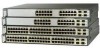
... and Cable Specifications." Pinouts for copper Ethernet connections and configures the interfaces accordingly. If the connected device also supports autonegotiation, the switch port negotiates the best connection (that is, the fastest line speed that the cable is autonegotiate.) When set the 10/100/1000 ports to...automatic crossover feature. Note On switches running Cisco IOS Release 12.1(14)EA1 or later, you can use Category 3 or Category 4 cables. Front Panel Description Chapter 2 Product Overview 10/100 and 10/100/1000 Ports You can set the 10/100 on the other end of the connection...
... and Cable Specifications." Pinouts for copper Ethernet connections and configures the interfaces accordingly. If the connected device also supports autonegotiation, the switch port negotiates the best connection (that is, the fastest line speed that the cable is autonegotiate.) When set the 10/100/1000 ports to...automatic crossover feature. Note On switches running Cisco IOS Release 12.1(14)EA1 or later, you can use Category 3 or Category 4 cables. Front Panel Description Chapter 2 Product Overview 10/100 and 10/100/1000 Ports You can set the 10/100 on the other end of the connection...

Hardware Installation Guide
Page 56
...fail. Note The Cisco RPS 300 does not support the Catalyst 3750G-24TS switches. Cisco RPS Connector Specific Cisco RPS modes support specific Catalyst 3750 switches: • Cisco RPS 300 (model PWR300-AC-RPS-N1) supports the Catalyst 3750-24TS, 3750G-24T, 3750G-12S, and 3750-48TS switches. • Cisco RPS 675 (model... 2 Product Overview Power Connectors The switch is an autoranging unit that supports input voltages between 100 and 240 VAC. You can also connect the Cisco RPS 300 or the Cisco RPS 675 to provide backup power if the switch internal power supply should be connected to the...
...fail. Note The Cisco RPS 300 does not support the Catalyst 3750G-24TS switches. Cisco RPS Connector Specific Cisco RPS modes support specific Catalyst 3750 switches: • Cisco RPS 300 (model PWR300-AC-RPS-N1) supports the Catalyst 3750-24TS, 3750G-24T, 3750G-12S, and 3750-48TS switches. • Cisco RPS 675 (model... 2 Product Overview Power Connectors The switch is an autoranging unit that supports input voltages between 100 and 240 VAC. You can also connect the Cisco RPS 300 or the Cisco RPS 675 to provide backup power if the switch internal power supply should be connected to the...

Hardware Installation Guide
Page 57
...Cisco RPS 675 has two output levels: -48V and 12V with a total maximum output power of network traffic. It automatically senses when the internal power supply of a connected device fails and provides power to the failed device, preventing loss of 675W. For more information on page B-1. 78-15136-02 Catalyst... Description Cisco RPS 675 The RPS is a redundant power system that can support six external network devices and provides power to one failed device at a time. For console port and adapter pinout information, see the "Connector and Cable Specifications" section on the Cisco RPS ...
...Cisco RPS 675 has two output levels: -48V and 12V with a total maximum output power of network traffic. It automatically senses when the internal power supply of a connected device fails and provides power to the failed device, preventing loss of 675W. For more information on page B-1. 78-15136-02 Catalyst... Description Cisco RPS 675 The RPS is a redundant power system that can support six external network devices and provides power to one failed device at a time. For console port and adapter pinout information, see the "Connector and Cable Specifications" section on the Cisco RPS ...

Hardware Installation Guide
Page 59
...) Cisco IE200 Series Configuration Registrar is a network management device that works with embedded CNS agents in the switch software. You can automate initial configurations and configuration updates by generating switch-specific configuration changes, sending them to create dedicated network segments and interconnecting the segments through Gigabit Ethernet connections. 78-15136-02 Catalyst 3750...
...) Cisco IE200 Series Configuration Registrar is a network management device that works with embedded CNS agents in the switch software. You can automate initial configurations and configuration updates by generating switch-specific configuration changes, sending them to create dedicated network segments and interconnecting the segments through Gigabit Ethernet connections. 78-15136-02 Catalyst 3750...

Hardware Installation Guide
Page 64
... occurs, the user may be requested to take appropriate countermeasures. Class A Notice for Installation Chapter 3 Switch Installation EMC Regulatory Statements This section includes specific regulatory statements about the Catalyst 3750 family of switches. If this manual. U.S. Preparing for Taiwan and Other Traditional Chinese Markets Warning This is used in a domestic environment, radio...
... occurs, the user may be requested to take appropriate countermeasures. Class A Notice for Installation Chapter 3 Switch Installation EMC Regulatory Statements This section includes specific regulatory statements about the Catalyst 3750 family of switches. If this manual. U.S. Preparing for Taiwan and Other Traditional Chinese Markets Warning This is used in a domestic environment, radio...

Hardware Installation Guide
Page 66
...Catalyst 3750 Switch Hardware Installation Guide 3-6 78-15136-02 The mode-conditioning patch cord is required for unrestricted cabling. Front-panel indicators can cause transceiver saturation, resulting in Appendix A, "Technical Specifications." • Clearance to 328 feet (100 meters). • Table 3-1 lists the cable specifications...link distance can be sure to observe these requirements: • For 10/100 and 10/100/1000 ports, cable lengths from the switch to connected devices are up to 328 feet (100 meters). • Copper 1000BASE-T SFP modules use standard four twisted-...
...Catalyst 3750 Switch Hardware Installation Guide 3-6 78-15136-02 The mode-conditioning patch cord is required for unrestricted cabling. Front-panel indicators can cause transceiver saturation, resulting in Appendix A, "Technical Specifications." • Clearance to 328 feet (100 meters). • Table 3-1 lists the cable specifications...link distance can be sure to observe these requirements: • For 10/100 and 10/100/1000 ports, cable lengths from the switch to connected devices are up to 328 feet (100 meters). • Copper 1000BASE-T SFP modules use standard four twisted-...

Hardware Installation Guide
Page 68
...Catalyst 3750-24TS, 3750G-24T, and 3750-48TS switches) - Note If you need to provide a RJ-45-to -DB-9 adapter cable. For console port and adapter pinout information, see the "Cable and Adapter Specifications..." section on the switch and observe POST: • Connecting a PC or Terminal to the Console Port, page 3-8 • Powering On the Switch and Running POST, page 3-10 ...switch and verify that adapter from Cisco. These sections describe the steps required to connect a PC to the switch console port, and to a rack - Catalyst 3750 Switch Hardware Installation Guide 3-8...
...Catalyst 3750-24TS, 3750G-24T, and 3750-48TS switches) - Note If you need to provide a RJ-45-to -DB-9 adapter cable. For console port and adapter pinout information, see the "Cable and Adapter Specifications..." section on the switch and observe POST: • Connecting a PC or Terminal to the Console Port, page 3-8 • Powering On the Switch and Running POST, page 3-10 ...switch and verify that adapter from Cisco. These sections describe the steps required to connect a PC to the switch console port, and to a rack - Catalyst 3750 Switch Hardware Installation Guide 3-8...

Hardware Installation Guide
Page 72
...Considerations, page 3-13 • Cabling Considerations, page 3-14 • Recommended Cabling Configurations, page 3-15 Planning Considerations Before connecting the Catalyst 3750 switches in a stack, observe these planning considerations: • Size of the switch. Stacking switches of the rack if you ... Catalyst 3750G-12S and 3750G-24T switches are planning to the rear ports for unrestricted cabling. For switch dimensions, go to Appendix A, "Technical Specifications." Planning the Stack Chapter 3 Switch Installation Planning the Stack If you plan to stack your Cisco supplier...
...Considerations, page 3-13 • Cabling Considerations, page 3-14 • Recommended Cabling Configurations, page 3-15 Planning Considerations Before connecting the Catalyst 3750 switches in a stack, observe these planning considerations: • Size of the switch. Stacking switches of the rack if you ... Catalyst 3750G-12S and 3750G-24T switches are planning to the rear ports for unrestricted cabling. For switch dimensions, go to Appendix A, "Technical Specifications." Planning the Stack Chapter 3 Switch Installation Planning the Stack If you plan to stack your Cisco supplier...

Hardware Installation Guide
Page 100
... and the cable must match the wave-length specifications on the front of SFP modules that is encoded with security information. Each port must not exceed the stipulated cable length for the switch. 3-40 Catalyst 3750 Switch Hardware Installation Guide 78-15136-02 ...validate that the SFP module meets the requirements for reliable communications. See the "Installation Guidelines" section on the Catalyst 3750 switch. This encoding provides a way for Cisco to the Catalyst 3750 release notes for SFP connections. You can use any combination of a StackWise Cable from a StackWise ...
... and the cable must match the wave-length specifications on the front of SFP modules that is encoded with security information. Each port must not exceed the stipulated cable length for the switch. 3-40 Catalyst 3750 Switch Hardware Installation Guide 78-15136-02 ...validate that the SFP module meets the requirements for reliable communications. See the "Installation Guidelines" section on the Catalyst 3750 switch. This encoding provides a way for Cisco to the Catalyst 3750 release notes for SFP connections. You can use any combination of a StackWise Cable from a StackWise ...

Hardware Installation Guide
Page 105
... Installation Connecting to the 10/100 and 10/100/1000 Ports Follow these steps to connect to an RJ-45 connector on the other end 78-15136-02 Catalyst 3750 Switch Hardware Installation Guide...See Figure 3-40.) When connecting to use a crossover cable. (See the "Cable and Adapter Specifications" section on , the device at the other device. Step 2 Connect the other end of ...Step 1 When connecting to workstations, servers, routers, and Cisco IP Phones, connect a straight-through cable for connections to a copper 10/100 or 10/100/1000 port on the switch, regardless the type of device ...
... Installation Connecting to the 10/100 and 10/100/1000 Ports Follow these steps to connect to an RJ-45 connector on the other end 78-15136-02 Catalyst 3750 Switch Hardware Installation Guide...See Figure 3-40.) When connecting to use a crossover cable. (See the "Cable and Adapter Specifications" section on , the device at the other device. Step 2 Connect the other end of ...Step 1 When connecting to workstations, servers, routers, and Cisco IP Phones, connect a straight-through cable for connections to a copper 10/100 or 10/100/1000 port on the switch, regardless the type of device ...

Hardware Installation Guide
Page 107
...-optic cable, and store them for loops. Insert the other cable end into the SFP module port (see Figure 3-41). See Appendix B, "Connector and Cable Specifications" for solutions to connect the cable. Observe the port status LED. Before connecting to the SFP module, be problem with the adapter installed in the... might not be turned on, there might be a cable problem, or there might be sure that you are ready to cabling problems. 78-15136-02 Catalyst 3750 Switch Hardware Installation Guide 3-47
...-optic cable, and store them for loops. Insert the other cable end into the SFP module port (see Figure 3-41). See Appendix B, "Connector and Cable Specifications" for solutions to connect the cable. Observe the port status LED. Before connecting to the SFP module, be problem with the adapter installed in the... might not be turned on, there might be a cable problem, or there might be sure that you are ready to cabling problems. 78-15136-02 Catalyst 3750 Switch Hardware Installation Guide 3-47

Hardware Installation Guide
Page 119
... Table A-2, Table A-3, Table A-4, Table A-5, and the regulatory agency approvals in Table A-6. Table A-1 Specifications for the Catalyst 3750G-12S Switch Environmental Ranges Operating temperature Storage temperature Relative humidity Operating altitude Storage altitude Power Requirements AC input voltage DC input voltages for RPS ... consumption Power rating 32 to 113°F (0 to 45°C) -13 to 158°F (-25 to 70°C) 10 to 85% (noncondensing) Up to 10,000 ft (3049 m) Up to 15,000 ft (4573 m) 100 to 240 VAC (autoranging) 1.2A/0.6A, 50 to 60 Hz +12V @13A +12V @13A 120 W, 409 BTUs ...
... Table A-2, Table A-3, Table A-4, Table A-5, and the regulatory agency approvals in Table A-6. Table A-1 Specifications for the Catalyst 3750G-12S Switch Environmental Ranges Operating temperature Storage temperature Relative humidity Operating altitude Storage altitude Power Requirements AC input voltage DC input voltages for RPS ... consumption Power rating 32 to 113°F (0 to 45°C) -13 to 158°F (-25 to 70°C) 10 to 85% (noncondensing) Up to 10,000 ft (3049 m) Up to 15,000 ft (4573 m) 100 to 240 VAC (autoranging) 1.2A/0.6A, 50 to 60 Hz +12V @13A +12V @13A 120 W, 409 BTUs ...

Hardware Installation Guide
Page 120
...-12S Switch (continued) Environmental Ranges Physical Dimensions Weight 10 lb (4.55 kg) Dimensions (H x D x W) 1.73 x 12.83 x 17.5 in. (4.39 x 32.59 x 44.45 cm) Table A-2 Specifications for the Catalyst 3750-24TS Switch Environmental Ranges Operating temperature Storage temperature Relative humidity Operating altitude Storage altitude Power Requirements AC ...rating 32 to 113°F (0 to 45°C) -13 to 158°F (-25 to 70°C) 10 to 85% (noncondensing) Up to 10,000 ft (3049 m) Up to 15,000 ft (4573 m) 100 to 240 VAC (autoranging) 1.2A/0.6A, 50 to 60 Hz +12V @8.5A +12V @8.5A 50W,...
...-12S Switch (continued) Environmental Ranges Physical Dimensions Weight 10 lb (4.55 kg) Dimensions (H x D x W) 1.73 x 12.83 x 17.5 in. (4.39 x 32.59 x 44.45 cm) Table A-2 Specifications for the Catalyst 3750-24TS Switch Environmental Ranges Operating temperature Storage temperature Relative humidity Operating altitude Storage altitude Power Requirements AC ...rating 32 to 113°F (0 to 45°C) -13 to 158°F (-25 to 70°C) 10 to 85% (noncondensing) Up to 10,000 ft (3049 m) Up to 15,000 ft (4573 m) 100 to 240 VAC (autoranging) 1.2A/0.6A, 50 to 60 Hz +12V @8.5A +12V @8.5A 50W,...

Hardware Installation Guide
Page 121
...Dimensions (H x D x W) 1.73 x 11.83 x 17.5 in. (4.39 x 30.05 x 44.45 cm) Table A-3 Specifications for the Catalyst 3750G-24T Switch Environmental Ranges Operating temperature 32 to 113°F (0 to 45°C) Storage temperature -13 to 158°F (-25 ...to 70°C) Relative humidity 10 to 85% (noncondensing) Operating altitude Up to 10,000 ft (3049 m) Storage altitude Up to 15,000 ft (4573 m) Power Requirements AC input voltage 100...
...Dimensions (H x D x W) 1.73 x 11.83 x 17.5 in. (4.39 x 30.05 x 44.45 cm) Table A-3 Specifications for the Catalyst 3750G-24T Switch Environmental Ranges Operating temperature 32 to 113°F (0 to 45°C) Storage temperature -13 to 158°F (-25 ...to 70°C) Relative humidity 10 to 85% (noncondensing) Operating altitude Up to 10,000 ft (3049 m) Storage altitude Up to 15,000 ft (4573 m) Power Requirements AC input voltage 100...

Hardware Installation Guide
Page 122
Appendix A Technical Specifications Table A-4 Specifications for the Catalyst 3750G-24TS Switch Environmental Ranges Operating temperature 32 to 113°F (0 to 45°C) Storage temperature -13 to 158°F (-25 to 70°C) Relative humidity 10 to 85% (noncondensing) Operating altitude Up to 10,000 ft (3049 m) Storage altitude Up to... (0 to 45°C) -13 to 158°F (-25 to 70°C) 10 to 85% (noncondensing) Up to 10,000 ft (3049 m) Up to 15,000 ft (4573 m) 100 to 240 VAC (autoranging) 1.2A/0.6A, 50 to 60 Hz Catalyst 3750 Switch Hardware Installation Guide A-4 78-15136-02
Appendix A Technical Specifications Table A-4 Specifications for the Catalyst 3750G-24TS Switch Environmental Ranges Operating temperature 32 to 113°F (0 to 45°C) Storage temperature -13 to 158°F (-25 to 70°C) Relative humidity 10 to 85% (noncondensing) Operating altitude Up to 10,000 ft (3049 m) Storage altitude Up to... (0 to 45°C) -13 to 158°F (-25 to 70°C) 10 to 85% (noncondensing) Up to 10,000 ft (3049 m) Up to 15,000 ft (4573 m) 100 to 240 VAC (autoranging) 1.2A/0.6A, 50 to 60 Hz Catalyst 3750 Switch Hardware Installation Guide A-4 78-15136-02

Hardware Installation Guide
Page 123
Appendix A Technical Specifications Table A-5 Specifications for the Catalyst 3750-48TS Switch (continued) Environmental Ranges DC input voltages for RPS 300 +... kg) Dimensions (H x D x W) 1.73 x 11.83 x 17.5 in. (4.39 x 30.05 x 44.45 cm) Table A-6 Catalyst 3750 Switch Agency Approvals Safety EMC UL to UL 60950, Third Edition FCC Part 15 Class A c-UL to CAN/CSA -C22.2 No. 60950-00..., Third Edition EN 55022 1998 Class A (CISPR 22) EN 55024 1998 Class A (CISPR 24) TUV/GS to EN 60950:2000 VCCI Class A CB to IEC 60950 with all country deviations AS/NZS 3548 Class A ...
Appendix A Technical Specifications Table A-5 Specifications for the Catalyst 3750-48TS Switch (continued) Environmental Ranges DC input voltages for RPS 300 +... kg) Dimensions (H x D x W) 1.73 x 11.83 x 17.5 in. (4.39 x 30.05 x 44.45 cm) Table A-6 Catalyst 3750 Switch Agency Approvals Safety EMC UL to UL 60950, Third Edition FCC Part 15 Class A c-UL to CAN/CSA -C22.2 No. 60950-00..., Third Edition EN 55022 1998 Class A (CISPR 22) EN 55024 1998 Class A (CISPR 24) TUV/GS to EN 60950:2000 VCCI Class A CB to IEC 60950 with all country deviations AS/NZS 3548 Class A ...

Hardware Installation Guide
Page 124
Appendix A Technical Specifications Catalyst 3750 Switch Hardware Installation Guide A-6 78-15136-02
Appendix A Technical Specifications Catalyst 3750 Switch Hardware Installation Guide A-6 78-15136-02

Hardware Installation Guide
Page 125
...-through cable for this feature, refer to enable the automatic crossover feature. Figure B-1 shows the pinout. Note On switches running Cisco IOS Release 12.1(14)EA1 or later, you can use the mdix auto command in the CLI to the switch software configuration ... connections and configures the interfaces accordingly. Connector Specifications These sections describe the connectors used with the Catalyst 3750 switches. 10/100/1000 Ports The 10/100/1000 Ethernet ports on Catalyst 3750 switches use to connect the switch to a copper 10/100 or 10/100/1000 port on the switch, regardless the...
...-through cable for this feature, refer to enable the automatic crossover feature. Figure B-1 shows the pinout. Note On switches running Cisco IOS Release 12.1(14)EA1 or later, you can use the mdix auto command in the CLI to the switch software configuration ... connections and configures the interfaces accordingly. Connector Specifications These sections describe the connectors used with the Catalyst 3750 switches. 10/100/1000 Ports The 10/100/1000 Ethernet ports on Catalyst 3750 switches use to connect the switch to a copper 10/100 or 10/100/1000 port on the switch, regardless the...