
Hardware Installation Guide
Page 6
... DC Power Connector 1-21 Cisco RPS Connector 1-22 Console Port 1-23 2 C H A P T E R Installation 2-1 Preparing for Installation 2-1 Warnings 2-1 EMC Regulatory Statements 2-4 U.S.A. 2-4 Taiwan 2-4 Japan 2-5 Korea 2-5 Hungary 2-6 Installation Guidelines 2-6 Verifying Package Contents 2-7 Installing the Switch on a Table or Shelf 2-9 Installing the Switch in a Rack 2-9 Removing Screws from the Switch 2-11 Attaching the Brackets to a Catalyst 2912 XL, 2924C XL...
... DC Power Connector 1-21 Cisco RPS Connector 1-22 Console Port 1-23 2 C H A P T E R Installation 2-1 Preparing for Installation 2-1 Warnings 2-1 EMC Regulatory Statements 2-4 U.S.A. 2-4 Taiwan 2-4 Japan 2-5 Korea 2-5 Hungary 2-6 Installation Guidelines 2-6 Verifying Package Contents 2-7 Installing the Switch on a Table or Shelf 2-9 Installing the Switch in a Rack 2-9 Removing Screws from the Switch 2-11 Attaching the Brackets to a Catalyst 2912 XL, 2924C XL...

Hardware Installation Guide
Page 7
...18 Attaching the Optional Cable Guide 2-19 Installing the Switch on a Wall 2-20 Attaching the Brackets to the Switch 2-21 Mounting the Switch to a Wall 2-22 Powering On the Switch and Running POST 2-24 Connecting to DC Power 2-25 Preparing for Installation 2-25 Grounding the Switch 2-26 Wiring the DC-Input Power Source 2-29... Correcting Module POST Failures 3-2 Diagnosing Problems 3-3 Technical Specifications A-1 Connectors and Cable Specifications B-1 Connector Specifications B-1 10/100 Ports B-1 100BASE-FX Ports B-2 Contents 78-6461-04 Catalyst 2900 Series XL Hardware Installation Guide vii
...18 Attaching the Optional Cable Guide 2-19 Installing the Switch on a Wall 2-20 Attaching the Brackets to the Switch 2-21 Mounting the Switch to a Wall 2-22 Powering On the Switch and Running POST 2-24 Connecting to DC Power 2-25 Preparing for Installation 2-25 Grounding the Switch 2-26 Wiring the DC-Input Power Source 2-29... Correcting Module POST Failures 3-2 Diagnosing Problems 3-3 Technical Specifications A-1 Connectors and Cable Specifications B-1 Connector Specifications B-1 10/100 Ports B-1 100BASE-FX Ports B-2 Contents 78-6461-04 Catalyst 2900 Series XL Hardware Installation Guide vii

Hardware Installation Guide
Page 9
.../Off Switch Warning C-24 Chassis Warning-Rack-Mounting and Servicing C-25 Reinforced Insulation Warning C-29 LAN Connections Only Warning C-30 No Field-Replaceable Units Warning C-31 Installation Warning C-32 SELV Source Warning C-33 Restricted Access Warning C-34 Shielded Ethernet Cables Warning... C-35 Grounded Equipment Warning C-36 Ground Connection Warning C-37 Qualified Personnel Warning C-38 DC Power Disconnection Warning C-39 Exposed Wire Lead Warning C-41 Contents 78-6461-04 Catalyst 2900 Series XL Hardware Installation ...
.../Off Switch Warning C-24 Chassis Warning-Rack-Mounting and Servicing C-25 Reinforced Insulation Warning C-29 LAN Connections Only Warning C-30 No Field-Replaceable Units Warning C-31 Installation Warning C-32 SELV Source Warning C-33 Restricted Access Warning C-34 Shielded Ethernet Cables Warning... C-35 Grounded Equipment Warning C-36 Ground Connection Warning C-37 Qualified Personnel Warning C-38 DC Power Disconnection Warning C-39 Exposed Wire Lead Warning C-41 Contents 78-6461-04 Catalyst 2900 Series XL Hardware Installation ...

Hardware Installation Guide
Page 11
... XL Hardware Installation Guide documents the hardware features of the switches, explains how to identify and resolve some of Ethernet and local area networking. Chapter 2, "Installation," provides the procedures for installing and configuring a Catalyst 2900 series XL switch. Chapter 3, "Troubleshooting," describes how to install a switch, and provides troubleshooting information and specifications. Preface Audience This guide...
... XL Hardware Installation Guide documents the hardware features of the switches, explains how to identify and resolve some of Ethernet and local area networking. Chapter 2, "Installation," provides the procedures for installing and configuring a Catalyst 2900 series XL switch. Chapter 3, "Troubleshooting," describes how to install a switch, and provides troubleshooting information and specifications. Preface Audience This guide...

Hardware Installation Guide
Page 12
...cables, and adapters that could result in this guide. Examples use these conventions: • Commands and keywords are in boldface. • Arguments for the switches and the regulatory agency approvals. Conventions This guide uses the following conventions and symbols: Note Means reader take note. Appendix C, "Translated Safety Warnings," provides ... materials not contained in this situation, you might do something that can be careful. Caution Means reader be used to connect to the switch. Catalyst 2900 Series XL Hardware Installation Guide xii 78-6461-04
...cables, and adapters that could result in this guide. Examples use these conventions: • Commands and keywords are in boldface. • Arguments for the switches and the regulatory agency approvals. Conventions This guide uses the following conventions and symbols: Note Means reader take note. Appendix C, "Translated Safety Warnings," provides ... materials not contained in this situation, you might do something that can be careful. Caution Means reader be used to connect to the switch. Catalyst 2900 Series XL Hardware Installation Guide xii 78-6461-04

Hardware Installation Guide
Page 15
... only in the "Obtaining Documentation" section on page xvi. • Release Notes for the Catalyst 2900 Series XL and Catalyst 3500 Series XL Switches (not orderable but is available on Cisco.com for the latest information. 78-6461-04 Catalyst 2900 Series XL Hardware Installation Guide xv Se förklaringar av de varningar som fö...
... only in the "Obtaining Documentation" section on page xvi. • Release Notes for the Catalyst 2900 Series XL and Catalyst 3500 Series XL Switches (not orderable but is available on Cisco.com for the latest information. 78-6461-04 Catalyst 2900 Series XL Hardware Installation Guide xv Se förklaringar av de varningar som fö...

Hardware Installation Guide
Page 16
...online help (available only from the switch CMS software) • Catalyst 2900 Series XL Hardware Installation Guide (order number DOC-786461=) • Catalyst 3500 Series XL Hardware Installation Guide (order number DOC-786456=) • Catalyst 2900 Series XL Modules Installation Guide ... number DOC-785472=) • 1000BASE-T Gigabit Interface Converter Installation Note (not orderable but is available on Cisco.com) • Catalyst GigaStack Gigabit Interface Converter Hardware Installation Guide (order number DOC-786460=) • Cisco LRE CPE Hardware Installation Guide (order number...
...online help (available only from the switch CMS software) • Catalyst 2900 Series XL Hardware Installation Guide (order number DOC-786461=) • Catalyst 3500 Series XL Hardware Installation Guide (order number DOC-786456=) • Catalyst 2900 Series XL Modules Installation Guide ... number DOC-785472=) • 1000BASE-T Gigabit Interface Converter Installation Note (not orderable but is available on Cisco.com) • Catalyst GigaStack Gigabit Interface Converter Hardware Installation Guide (order number DOC-786460=) • Cisco LRE CPE Hardware Installation Guide (order number...

Hardware Installation Guide
Page 21
...meters). The 2900 XL LRE switches employ Long-Reach Ethernet (LRE), a very-high-data-rate digital subscriber line (VDSL)-based technology that describe the Catalyst 2900 series XL switches, hereafter referred to as the switches. • Switch features, including management options &#...can be deployed as servers, routers, and other network devices. The switches can connect workstations, Cisco IP Phones, and other network devices such as backbone switches, aggregating 10/100 and Gigabit Ethernet traffic from other switches. CH A P T E R 1 Product Overview This chapter provides ...
...meters). The 2900 XL LRE switches employ Long-Reach Ethernet (LRE), a very-high-data-rate digital subscriber line (VDSL)-based technology that describe the Catalyst 2900 series XL switches, hereafter referred to as the switches. • Switch features, including management options &#...can be deployed as servers, routers, and other network devices. The switches can connect workstations, Cisco IP Phones, and other network devices such as backbone switches, aggregating 10/100 and Gigabit Ethernet traffic from other switches. CH A P T E R 1 Product Overview This chapter provides ...

Hardware Installation Guide
Page 22
... for 10BASE-T/100BASE-TX, 1000BASE-X, 1000BASE-T, Gigabit Ethernet, and asynchronous transfer mode (ATM) modules • On the Catalyst 2924M XL DC switch, a direct current (DC) power converter • On the Catalyst 2912 LRE XL and 2924 LRE XL switches, up to 24 LRE ports through one RJ-21 connector and hot swapping capability with the Cisco LRE customer...
... for 10BASE-T/100BASE-TX, 1000BASE-X, 1000BASE-T, Gigabit Ethernet, and asynchronous transfer mode (ATM) modules • On the Catalyst 2924M XL DC switch, a direct current (DC) power converter • On the Catalyst 2912 LRE XL and 2924 LRE XL switches, up to 24 LRE ports through one RJ-21 connector and hot swapping capability with the Cisco LRE customer...

Hardware Installation Guide
Page 23
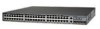
Chapter 1 Product Overview Figure 1-1 Catalyst 2900 Series XL Switches Version Number Description WS-C2912-LRE-XL 4 fixed autosensing 10/100 ports INPUT OUTPUT PWR PWR RESET TEMP FAN 9X 10X 11X 12X 12 LRE ports Cisco RPS 300 WS-C2924-LRE-XL 4 fixed autosensing 10/100 ports 24 LRE ports INPUT OUTPUT PWR PWR... RESET TEMP FAN 9X 10X 11X 12X Cisco RPS 300 WS-C2912-XL 12 fixed autosensing 10/100 ports MODE 1X 2X 3X 4X 5X 6X 7X 8X 9X 10X 10BaseT/100BASE-TX 11X 12X Catalyst 2900 SERIES XL WS-C2924C-XL 22 fixed autosensing 10/100 ports...
Chapter 1 Product Overview Figure 1-1 Catalyst 2900 Series XL Switches Version Number Description WS-C2912-LRE-XL 4 fixed autosensing 10/100 ports INPUT OUTPUT PWR PWR RESET TEMP FAN 9X 10X 11X 12X 12 LRE ports Cisco RPS 300 WS-C2924-LRE-XL 4 fixed autosensing 10/100 ports 24 LRE ports INPUT OUTPUT PWR PWR... RESET TEMP FAN 9X 10X 11X 12X Cisco RPS 300 WS-C2912-XL 12 fixed autosensing 10/100 ports MODE 1X 2X 3X 4X 5X 6X 7X 8X 9X 10X 10BaseT/100BASE-TX 11X 12X Catalyst 2900 SERIES XL WS-C2924C-XL 22 fixed autosensing 10/100 ports...

Hardware Installation Guide
Page 24
...Simple network management protocol (SNMP)-SNMP provides a means to the Catalyst 2900 Series XL and Catalyst 3500 Series XL Software Configuration Guide. and port-level settings. • Command-line Interface (CLI)-The switch IOS CLI software is a graphical user interface that can be ...-FX ports (See Figure 1-3), two module slots (see Figure 1-3), and up to twenty-four Long-Reach Ethernet ports (See Figure 1-4). You can manage switch configuration settings, performance, security, and collect statistics by using SNMP management applications such as Netscape Communicator or Microsoft...
...Simple network management protocol (SNMP)-SNMP provides a means to the Catalyst 2900 Series XL and Catalyst 3500 Series XL Software Configuration Guide. and port-level settings. • Command-line Interface (CLI)-The switch IOS CLI software is a graphical user interface that can be ...-FX ports (See Figure 1-3), two module slots (see Figure 1-3), and up to twenty-four Long-Reach Ethernet ports (See Figure 1-4). You can manage switch configuration settings, performance, security, and collect statistics by using SNMP management applications such as Netscape Communicator or Microsoft...

Hardware Installation Guide
Page 26
... connectors and Category 3, 4, or 5 cabling • 100BASE-TX-compatible devices, such as high-speed workstations, Cisco IP Phones, servers, hubs, routers, and other switches through , twisted-pair cable. The 10/100 ports on the Catalyst 3524-PWR XL switch, refer to switches or hubs, use Category 3 and 4 cables. Cisco IP Phones-connected to the 10/100 port...
... connectors and Category 3, 4, or 5 cabling • 100BASE-TX-compatible devices, such as high-speed workstations, Cisco IP Phones, servers, hubs, routers, and other switches through , twisted-pair cable. The 10/100 ports on the Catalyst 3524-PWR XL switch, refer to switches or hubs, use Category 3 and 4 cables. Cisco IP Phones-connected to the 10/100 port...

Hardware Installation Guide
Page 27
... be used. Long-Reach Ethernet Ports The Long-Reach Ethernet (LRE) ports (Figure 1-4) use one RJ-21 connector to connect up to 6562 feet (2 kilometers). For information about the Cisco LRE CPE devices, refer to the Catalyst 2900 Series XL and Catalyst 3500 Series XL Software Configuration Guide. If the other switch ports. For more information...
... be used. Long-Reach Ethernet Ports The Long-Reach Ethernet (LRE) ports (Figure 1-4) use one RJ-21 connector to connect up to 6562 feet (2 kilometers). For information about the Cisco LRE CPE devices, refer to the Catalyst 2900 Series XL and Catalyst 3500 Series XL Software Configuration Guide. If the other switch ports. For more information...

Hardware Installation Guide
Page 28
...to the patch panel. Each module port is internally switched to other switch ports and is not needed, and the switch can connect directly to share lines with LRE signals. Note Cisco Long-Reach Ethernet (LRE) products are for the Cisco LRE 48 POTS Splitter. For more information about homologated...XL WS-X2922-XL-V WS-X2924-XL-V Catalyst 2900 Series XL Hardware Installation Guide 1-8 78-6461-04 Due to the proprietary nature of digital PBX switches, some digital PBX switch services use the 0 to the Installation Notes for the Catalyst 2900 XL hot-swappable modules. Front-Panel ...
...to the patch panel. Each module port is internally switched to other switch ports and is not needed, and the switch can connect directly to share lines with LRE signals. Note Cisco Long-Reach Ethernet (LRE) products are for the Cisco LRE 48 POTS Splitter. For more information about homologated...XL WS-X2922-XL-V WS-X2924-XL-V Catalyst 2900 Series XL Hardware Installation Guide 1-8 78-6461-04 Due to the proprietary nature of digital PBX switches, some digital PBX switch services use the 0 to the Installation Notes for the Catalyst 2900 XL hot-swappable modules. Front-Panel ...

Hardware Installation Guide
Page 29
... ATM Modules Installation and Configuration Guide for detailed information on self-test (POST) verifies that switch. The Ethernet Gigabit module supports several Gigabit Interface Converter (GBIC) devices. A power-on expansion modules for the Catalyst 2900 Series XL and Catalyst 3500 Series XL Switches. For a complete list and the minimum software release required, refer to select a port mode...
... ATM Modules Installation and Configuration Guide for detailed information on self-test (POST) verifies that switch. The Ethernet Gigabit module supports several Gigabit Interface Converter (GBIC) devices. A power-on expansion modules for the Catalyst 2900 Series XL and Catalyst 3500 Series XL Switches. For a complete list and the minimum software release required, refer to select a port mode...

Hardware Installation Guide
Page 30
...Mode RPS button LED 47288 1-10 Catalyst 2900 Series XL Hardware Installation Guide 78-6461-04 The Catalyst 2900 Series XL and Catalyst 3500 Series XL Software Configuration Guide describes how to use CMS to manage standalone or individual switches and how to use cluster management ...software to manage switch clusters]. Front-Panel Description Chapter 1 Product...
...Mode RPS button LED 47288 1-10 Catalyst 2900 Series XL Hardware Installation Guide 78-6461-04 The Catalyst 2900 Series XL and Catalyst 3500 Series XL Software Configuration Guide describes how to use CMS to manage standalone or individual switches and how to use cluster management ...software to manage switch clusters]. Front-Panel Description Chapter 1 Product...

Hardware Installation Guide
Page 32
...LED colors and their meanings. For information on the System LED colors during POST, see the "Powering On the Switch and Running POST" section on page 2-24. 1-12 Catalyst 2900 Series XL Hardware Installation Guide 78-6461-04 System is not functioning properly. System is receiving power but is... operating normally. Front-Panel Description Figure 1-7 Catalyst 2912 LRE XL and 2924 LRE XL LEDs 10/100 port LEDs Chapter 1 Product Overview SYSTEM RPS MODE LRE STAT DUPLX SPEED ...
...LED colors and their meanings. For information on the System LED colors during POST, see the "Powering On the Switch and Running POST" section on page 2-24. 1-12 Catalyst 2900 Series XL Hardware Installation Guide 78-6461-04 System is not functioning properly. System is receiving power but is... operating normally. Front-Panel Description Figure 1-7 Catalyst 2912 LRE XL and 2924 LRE XL LEDs 10/100 port LEDs Chapter 1 Product Overview SYSTEM RPS MODE LRE STAT DUPLX SPEED ...

Hardware Installation Guide
Page 33
... mode. Table 1-2 and Table 1-3 list the RPS LED colors and their meanings. All other Catalyst 2900 XL and Catalyst 3500 XL switches use the Cisco RPS 300 (model PWR300-AC-RPS-N1). Pressing the Mode button on the Catalyst 2912 XL, 2924C XL, 2924 XL, 2924MF XL, 2924M XL, and 2924M XL DC... is off or not properly connected. The RPS and the switch AC power supply are both powered up power, if required. Chapter 1 Product Overview Front-Panel Description RPS LED The Catalyst 2912 LRE XL and Catalyst 2924 LRE XL switches use the Cisco RPS 600 (model PWR600-AC-RPS). Refer to provide back...
... mode. Table 1-2 and Table 1-3 list the RPS LED colors and their meanings. All other Catalyst 2900 XL and Catalyst 3500 XL switches use the Cisco RPS 300 (model PWR300-AC-RPS-N1). Pressing the Mode button on the Catalyst 2912 XL, 2924C XL, 2924 XL, 2924MF XL, 2924M XL, and 2924M XL DC... is off or not properly connected. The RPS and the switch AC power supply are both powered up power, if required. Chapter 1 Product Overview Front-Panel Description RPS LED The Catalyst 2912 LRE XL and Catalyst 2924 LRE XL switches use the Cisco RPS 600 (model PWR600-AC-RPS). Refer to provide back...

Hardware Installation Guide
Page 34
Contact Cisco Systems. The internal power supply in a switch has failed, and the RPS is the default mode. Port ...switch. (See Figure 1-8.) The port duplex mode: full duplex or half duplex, and default modes: • 10/100 ports: auto • 100BaseFX ports: auto • Gigabit ports: auto The port operating speed: 10 or 100 Mbps. 1-14 Catalyst... 1-6 and Table 1-7 list the port LED colors. Press the Standby/Active button on the Catalyst 2912 LRE XL and 2924 LRE XL Switches (continued) Color Solid amber Blinking amber RPS Status The RPS is highlighted. Front-Panel Description ...
Contact Cisco Systems. The internal power supply in a switch has failed, and the RPS is the default mode. Port ...switch. (See Figure 1-8.) The port duplex mode: full duplex or half duplex, and default modes: • 10/100 ports: auto • 100BaseFX ports: auto • Gigabit ports: auto The port operating speed: 10 or 100 Mbps. 1-14 Catalyst... 1-6 and Table 1-7 list the port LED colors. Press the Standby/Active button on the Catalyst 2912 LRE XL and 2924 LRE XL Switches (continued) Color Solid amber Blinking amber RPS Status The RPS is highlighted. Front-Panel Description ...

Hardware Installation Guide
Page 35
... Catalyst 2900 XL and Catalyst 3500 XL switches except the Catalyst 2912 LRE XL and Catalyst 2924 LRE XL switches. The port duplex mode: full duplex or half duplex. The default setting is active, the 10/100 switch ports on the Catalyst 2912 LRE XL and Catalyst 2924 LRE XL continue to show Ethernet .... Note When the LRE mode is half duplex. The default setting is auto. 78-6461-04 Catalyst 2900 Series XL Hardware Installation Guide 1-15 Default mode on these switches only. Ethernet link status of the LRE ports on the remote CPE. Chapter 1 Product Overview Front-Panel Description ...
... Catalyst 2900 XL and Catalyst 3500 XL switches except the Catalyst 2912 LRE XL and Catalyst 2924 LRE XL switches. The port duplex mode: full duplex or half duplex. The default setting is active, the 10/100 switch ports on the Catalyst 2912 LRE XL and Catalyst 2924 LRE XL continue to show Ethernet .... Note When the LRE mode is half duplex. The default setting is auto. 78-6461-04 Catalyst 2900 Series XL Hardware Installation Guide 1-15 Default mode on these switches only. Ethernet link status of the LRE ports on the remote CPE. Chapter 1 Product Overview Front-Panel Description ...


