Getting Started Guide
Page 4
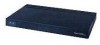
... Null modem serial cable (DB-9 -> RJ-45) to console connection Cisco WCS software, web user interface 10/100/1000BASE-T MDI cable Network Distribution system connection LAN link for management software connections WAN or LAN connection to Cisco 2500 Series Wireless Controllers are not currently ...of your network and have a working knowledge of access points to main office 10/100/1000BASE-T MDI cables Access point connections 282297 Cisco Access Points 4 To best use straight-through or crossover cables. Figure 1 shows a 2504 controller network topology and network connections,...
... Null modem serial cable (DB-9 -> RJ-45) to console connection Cisco WCS software, web user interface 10/100/1000BASE-T MDI cable Network Distribution system connection LAN link for management software connections WAN or LAN connection to Cisco 2500 Series Wireless Controllers are not currently ...of your network and have a working knowledge of access points to main office 10/100/1000BASE-T MDI cables Access point connections 282297 Cisco Access Points 4 To best use straight-through or crossover cables. Figure 1 shows a 2504 controller network topology and network connections,...
Getting Started Guide
Page 5
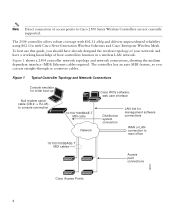
... the controller configures the RS-232 port as a console port with default settings of the front panel. Figure 2 Front Panel and LEDs 282249 CONSOLE CONSOLE CISCO 2500 Series WIRELESS CONTROLLER RESET Model 2504 1 2 3 4 PWR SYS ALM RESET 1 2 3-4 POE PWR ALM SYS Table 1 Callout WLC2504 Front Panel Component Descriptions Port and LEDs..., 57600, and 115200. Figure 2 shows the front panel and location of the allowed values before setting the baud rate. however the bootloader ensures that supports a RJ-45 connector.
... the controller configures the RS-232 port as a console port with default settings of the front panel. Figure 2 Front Panel and LEDs 282249 CONSOLE CONSOLE CISCO 2500 Series WIRELESS CONTROLLER RESET Model 2504 1 2 3 4 PWR SYS ALM RESET 1 2 3-4 POE PWR ALM SYS Table 1 Callout WLC2504 Front Panel Component Descriptions Port and LEDs..., 57600, and 115200. Figure 2 shows the front panel and location of the allowed values before setting the baud rate. however the bootloader ensures that supports a RJ-45 connector.

Getting Started Guide
Page 6
... The Gigabit POE ports are PoE only ports; This port is designed so that 1500 VAC rms isolation (per the 802.3 specification) is an RJ-45 connector form-factor. LED description: • Green or Blinking Green-Link activity • Off-No link 3 & 4 POE GigE Power-over... configured to these ports. They provide a I2C communications channel between chassis ground and any 48V/Ethernet signal. The POE controller reset is an RJ-45 connector form-factor. LED description: • Green or Blinking Green-Link activity • Off-No link 2 GigE port and LED The...
... The Gigabit POE ports are PoE only ports; This port is designed so that 1500 VAC rms isolation (per the 802.3 specification) is an RJ-45 connector form-factor. LED description: • Green or Blinking Green-Link activity • Off-No link 3 & 4 POE GigE Power-over... configured to these ports. They provide a I2C communications channel between chassis ground and any 48V/Ethernet signal. The POE controller reset is an RJ-45 connector form-factor. LED description: • Green or Blinking Green-Link activity • Off-No link 2 GigE port and LED The...
Getting Started Guide
Page 21
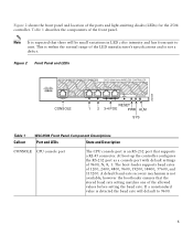
...emulation program for basic operations, you need to connect it falls and prevents the connector from being sheared off at the plug pins. Note The Cisco 2106 power adapter is pulled or if the power adapter falls. To secure the power adapter cable and plug, follow these steps: 21 To ... Console Port Caution Do not connect a Power over Ethernet (PoE) cable to the controller console port, follow these steps: Step 1 Step 2 Step 3 Plug the RJ-45 connector on a null-modem serial cable into the controller console port and the other end of the cable into the serial port of the PC.
...emulation program for basic operations, you need to connect it falls and prevents the connector from being sheared off at the plug pins. Note The Cisco 2106 power adapter is pulled or if the power adapter falls. To secure the power adapter cable and plug, follow these steps: 21 To ... Console Port Caution Do not connect a Power over Ethernet (PoE) cable to the controller console port, follow these steps: Step 1 Step 2 Step 3 Plug the RJ-45 connector on a null-modem serial cable into the controller console port and the other end of the cable into the serial port of the PC.
Getting Started Guide
Page 34
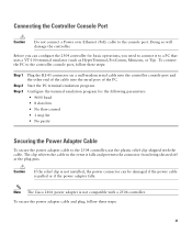
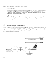
...without saving any alphanumeric string up to the controller. Figure 13 External Network Equipment Connection to the Controller 10/100/1000BASE-T MDI cable Cisco Access Points CLI console Connection to CISCO2504, enter config prompt "CISCO2504" and press Enter. You can set the automatic logout from ...prompt: #(system prompt)> The system prompt can be any changes after 5 minutes of inactivity. The connection uses 10/100/1000BASE-T Ethernet (RJ-45 physical port, UTP, Category-5 or higher cable). Make sure you enter the new prompt using the config serial timeout command. 6 Connecting ...
...without saving any alphanumeric string up to the controller. Figure 13 External Network Equipment Connection to the Controller 10/100/1000BASE-T MDI cable Cisco Access Points CLI console Connection to CISCO2504, enter config prompt "CISCO2504" and press Enter. You can set the automatic logout from ...prompt: #(system prompt)> The system prompt can be any changes after 5 minutes of inactivity. The connection uses 10/100/1000BASE-T Ethernet (RJ-45 physical port, UTP, Category-5 or higher cable). Make sure you enter the new prompt using the config serial timeout command. 6 Connecting ...
