

Hardware Installation Guide
Page 2
...in accordance with the specifications in part 15 of Class B devices: The equipment described in this manual generates and may cause harmful interference to the Human Network are trademarks of Cisco Systems, Inc.; and/or its peripheral devices. All other trademarks mentioned in this document or ... INCLUDING, WITHOUT LIMITATION, LOST PROFITS OR LOSS OR DAMAGE TO DATA ARISING OUT OF THE USE OR INABILITY TO USE THIS MANUAL, EVEN IF CISCO OR ITS SUPPLIERS HAVE BEEN ADVISED OF THE POSSIBILITY OF SUCH DAMAGES. These specifications are registered trademarks of the UNIX operating system...
...in accordance with the specifications in part 15 of Class B devices: The equipment described in this manual generates and may cause harmful interference to the Human Network are trademarks of Cisco Systems, Inc.; and/or its peripheral devices. All other trademarks mentioned in this document or ... INCLUDING, WITHOUT LIMITATION, LOST PROFITS OR LOSS OR DAMAGE TO DATA ARISING OUT OF THE USE OR INABILITY TO USE THIS MANUAL, EVEN IF CISCO OR ITS SUPPLIERS HAVE BEEN ADVISED OF THE POSSIBILITY OF SUCH DAMAGES. These specifications are registered trademarks of the UNIX operating system...
Hardware Installation Guide
Page 6
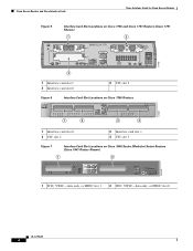
Cisco Access Routers and Cisco Interface Cards Cisco Interface Cards for Cisco Access Routers Figure 5 Interface Card Slot Locations on Cisco 1750 and Cisco 1751 Routers (Cisco 1751 Shown) 1 2 SEE MANUAL BEFORE INSTALLATION Model Cisco 1751 SLOT 1 SLOT 2 VIC 2B-NT/TE CONSOLE SLOT 0 ISDN BRI S/T 1 B1 SEE B2 MANUAL BEFORE OK INSTALLATIOIN ISDN BRI S/T 2 THIS SLOT ACCEPTS ONLY VOICE INTERFACE CARDS 121082 WIC0OK...
Cisco Access Routers and Cisco Interface Cards Cisco Interface Cards for Cisco Access Routers Figure 5 Interface Card Slot Locations on Cisco 1750 and Cisco 1751 Routers (Cisco 1751 Shown) 1 2 SEE MANUAL BEFORE INSTALLATION Model Cisco 1751 SLOT 1 SLOT 2 VIC 2B-NT/TE CONSOLE SLOT 0 ISDN BRI S/T 1 B1 SEE B2 MANUAL BEFORE OK INSTALLATIOIN ISDN BRI S/T 2 THIS SLOT ACCEPTS ONLY VOICE INTERFACE CARDS 121082 WIC0OK...
Hardware Installation Guide
Page 62
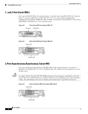
...LED 41210 CONN SERIAL Figure 33 2-Port Serial WIC Front Panel (WIC-2T) Serial ports SERIAL 1 CONN SERIAL 0 WIC CONN 2T SEE MANUAL BEFORE INSTALLATION 41213 CONN LEDs 2-Port Asynchronous/Synchronous Serial WIC The 2-port asynchronous/synchronous (A/S) WIC (WIC-2A/S), shown in Figure 33, provide...data communications equipment (DTE/DCE), EIA-530 DTE, or nonreturn to zero/nonreturn to zero inverted (NRZ/NRZI) serial interface to a Cisco modular router. The intrabuilding cable must be shielded and the shield must be grounded at both ends. and 2-Port Serial WICs The 1-port serial ...
...LED 41210 CONN SERIAL Figure 33 2-Port Serial WIC Front Panel (WIC-2T) Serial ports SERIAL 1 CONN SERIAL 0 WIC CONN 2T SEE MANUAL BEFORE INSTALLATION 41213 CONN LEDs 2-Port Asynchronous/Synchronous Serial WIC The 2-port asynchronous/synchronous (A/S) WIC (WIC-2A/S), shown in Figure 33, provide...data communications equipment (DTE/DCE), EIA-530 DTE, or nonreturn to zero/nonreturn to zero inverted (NRZ/NRZI) serial interface to a Cisco modular router. The intrabuilding cable must be shielded and the shield must be grounded at both ends. and 2-Port Serial WICs The 1-port serial ...
Hardware Installation Guide
Page 65
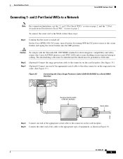
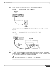
...the connector on the surge protector cable. (See Figure 35.) Figure 35 Connecting the Cisco Surge Protector Cable (CAB-SS-SURGE) to a Serial WAN Interface SERIAL 1 CONN SERIAL 0 WIC CONN 2T SEE MANUAL BEFORE INSTALLATION Surge protection cable (CAB-SS-SURGE) Serial cable 95969 Step 4 Connect ... faceplate. (See Figure 35.) (Optional) Connect one end of equipment, as shown in Figure 36. OL-12843-01 5 On the Cisco MWR 1941-DC router, turn off . Caution To comply with the Telcordia GR-1089 NEBS standard for electromagnetic compatibility and safety, connect the 2-port A/S WAN ...
...the connector on the surge protector cable. (See Figure 35.) Figure 35 Connecting the Cisco Surge Protector Cable (CAB-SS-SURGE) to a Serial WAN Interface SERIAL 1 CONN SERIAL 0 WIC CONN 2T SEE MANUAL BEFORE INSTALLATION Surge protection cable (CAB-SS-SURGE) Serial cable 95969 Step 4 Connect ... faceplate. (See Figure 35.) (Optional) Connect one end of equipment, as shown in Figure 36. OL-12843-01 5 On the Cisco MWR 1941-DC router, turn off . Caution To comply with the Telcordia GR-1089 NEBS standard for electromagnetic compatibility and safety, connect the 2-port A/S WAN ...
Hardware Installation Guide
Page 76
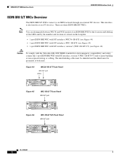
...wiring or cabling. Figure 44 WIC36-1B-S/T Front Panel BRI S/T port LEDs 41225 B1 B2 SEE MANUAL BEFORE INSTALLATION BRI S/T Figure 45 WIC-1B-S/T Front Panel BRI S/T port B1 B2 OK 41221 SEE MANUAL BEFORE INSTALLATION BRI S/T Figure 46 WIC-1B-S/T-V3 Front Panel BRI S/T port WIC 1B-S/T V3... SEE MANUAL BEFORE INSTALLATION B1 B2 ISDN BRI S/T OK 95120 OL-12844-01 2 The intrabuilding cable must ...
...wiring or cabling. Figure 44 WIC36-1B-S/T Front Panel BRI S/T port LEDs 41225 B1 B2 SEE MANUAL BEFORE INSTALLATION BRI S/T Figure 45 WIC-1B-S/T Front Panel BRI S/T port B1 B2 OK 41221 SEE MANUAL BEFORE INSTALLATION BRI S/T Figure 46 WIC-1B-S/T-V3 Front Panel BRI S/T port WIC 1B-S/T V3... SEE MANUAL BEFORE INSTALLATION B1 B2 ISDN BRI S/T OK 95120 OL-12844-01 2 The intrabuilding cable must ...
Hardware Installation Guide
Page 79
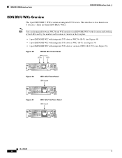
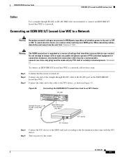
... ISDN BRI S/T WIC to an NT1 Device Straight-through RJ-48C-to-RJ-48C cable to the router. ISDN BRI U WAN Interface Cards This section describes how to connect ISDN BRI U WICs to a..., as shown in Figure 48. Connect the other end of a straight-through RJ-48C-to-RJ-48C cable SEE MANUAL BEFORE INSTALLATION BRI S/T BRI S/T port (RJ-48C) B1 B2 OK 41193 NT1 device Step 4 Step 5 Step ... power to the RJ-48C port on , which indicates that came with the NT1 device. Check that the router is turned off. Step 2 Step 3 Connect one end of the cable to intra-building or non-exposed wiring...
... ISDN BRI S/T WIC to an NT1 Device Straight-through RJ-48C-to-RJ-48C cable to the router. ISDN BRI U WAN Interface Cards This section describes how to connect ISDN BRI U WICs to a..., as shown in Figure 48. Connect the other end of a straight-through RJ-48C-to-RJ-48C cable SEE MANUAL BEFORE INSTALLATION BRI S/T BRI S/T port (RJ-48C) B1 B2 OK 41193 NT1 device Step 4 Step 5 Step ... power to the RJ-48C port on , which indicates that came with the NT1 device. Check that the router is turned off. Step 2 Step 3 Connect one end of the cable to intra-building or non-exposed wiring...
Hardware Installation Guide
Page 80
... integrated NT1 device, version 2(WIC-1B-U-V2) (see Figure 51) Figure 49 WIC36-1B-U Front Panel BRI U port LEDs LED NT1 41226 B1 B2 SEE MANUAL BEFORE INSTALLATION BRI U Figure 50 WIC-1B-U Front Panel BRI U port B1 B2 NT1 41223 SEE...
... integrated NT1 device, version 2(WIC-1B-U-V2) (see Figure 51) Figure 49 WIC36-1B-U Front Panel BRI U port LEDs LED NT1 41226 B1 B2 SEE MANUAL BEFORE INSTALLATION BRI U Figure 50 WIC-1B-U Front Panel BRI U port B1 B2 NT1 41223 SEE...
Hardware Installation Guide
Page 83
The intra-building port(s) of a straight-through RJ-48C-to the router. Step 2 Step 3 Connect one end of the equipment or subassembly must ...cabling. Figure 53 Connecting an ISDN BRI U WIC to an ISDN Wall Jack BRI U port (RJ-48C) SEE MANUAL BEFORE INSTALLATION BRI U Straight-through RJ-48C-to-RJ-48C cable to the RJ-48C port on power to -... ISDN BRI U WIC to a Network OL-12844-01 9 Check that the OK LED goes on, which indicates that the router is not sufficient protection in order to connect these steps: Step 1 Confirm that the ISDN port has established a connection with...
The intra-building port(s) of a straight-through RJ-48C-to the router. Step 2 Step 3 Connect one end of the equipment or subassembly must ...cabling. Figure 53 Connecting an ISDN BRI U WIC to an ISDN Wall Jack BRI U port (RJ-48C) SEE MANUAL BEFORE INSTALLATION BRI U Straight-through RJ-48C-to-RJ-48C cable to the RJ-48C port on power to -... ISDN BRI U WIC to a Network OL-12844-01 9 Check that the OK LED goes on, which indicates that the router is not sufficient protection in order to connect these steps: Step 1 Confirm that the ISDN port has established a connection with...
Hardware Installation Guide
Page 84
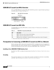
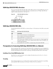
... This section describes the preparation necessary before connecting an ISDN BRI U WIC to the instructions in Installing Cisco Interface Cards in Cisco Access Routers. Installing a Cisco ISDN BRI S/T WAN Interface Card Install the Cisco WIC according to the network. B21 ISDN connection on B1 channel when blinking. For instructions on B1 only...-line mode at 64-kbps. (See Figure 54.) Figure 54 WIC-1B-S/T-LL Front Panel ISDN BRI port 41216 BRI S/T LL SEE MANUAL BEFORE INSTALLATION B1 LED B2 LED OK LED ISDN BRI S/T Leased-Line WIC LEDs The ISDN BRI S/T leased-line WIC LEDs are described...
... This section describes the preparation necessary before connecting an ISDN BRI U WIC to the instructions in Installing Cisco Interface Cards in Cisco Access Routers. Installing a Cisco ISDN BRI S/T WAN Interface Card Install the Cisco WIC according to the network. B21 ISDN connection on B1 channel when blinking. For instructions on B1 only...-line mode at 64-kbps. (See Figure 54.) Figure 54 WIC-1B-S/T-LL Front Panel ISDN BRI port 41216 BRI S/T LL SEE MANUAL BEFORE INSTALLATION B1 LED B2 LED OK LED ISDN BRI S/T Leased-Line WIC LEDs The ISDN BRI S/T leased-line WIC LEDs are described...
Hardware Installation Guide
Page 85
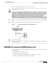
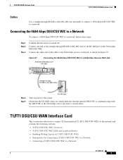
...-line WIC. ISDN BRI WAN Interface Cards ISDN BRI S/T Leased-Line WAN Interface Card Cables Use a straight-through RJ-48C-to-RJ-48C cable SEE MANUAL BEFORE INSTALLATION BRI S/T LL ISDN BRI leased line interface (RJ-48C) 41191 S/T interface NT1 device Step 4 Step 5 Connect the NT1 device to the ...ISDN wall jack according to the documentation that the router is turned off. OL-12844-01 11 Any hardwired connection (other end of whether power to the unit is OFF or ON. Connecting an ISDN...
...-line WIC. ISDN BRI WAN Interface Cards ISDN BRI S/T Leased-Line WAN Interface Card Cables Use a straight-through RJ-48C-to-RJ-48C cable SEE MANUAL BEFORE INSTALLATION BRI S/T LL ISDN BRI leased line interface (RJ-48C) 41191 S/T interface NT1 device Step 4 Step 5 Connect the NT1 device to the ...ISDN wall jack according to the documentation that the router is turned off. OL-12844-01 11 Any hardwired connection (other end of whether power to the unit is OFF or ON. Connecting an ISDN...
Hardware Installation Guide
Page 90
...to the DTE interface. For instructions on grounding your serial WIC, refer to the instructions in Installing Cisco Interface Cards in the WIC is off during normal operation. RD Data is being received from the...Figure 56. or 64-kbps port LEDs LED TD RD LP AL CD 41224 SEE MANUAL BEFORE INSTALLATION DSU 56K 56/64-kbps DSU/CSU WIC LEDs The 56/64-kbps DSU/CSU ...an integral DSU/CSU and can be configured to the network. Grounding Ensure that the WIC is in Cisco Access Routers. This WIC also supports 64-kbps dedicated lines. (See Figure 56.) Figure 56 WIC-1DSU-56K4 ...
...to the DTE interface. For instructions on grounding your serial WIC, refer to the instructions in Installing Cisco Interface Cards in the WIC is off during normal operation. RD Data is being received from the...Figure 56. or 64-kbps port LEDs LED TD RD LP AL CD 41224 SEE MANUAL BEFORE INSTALLATION DSU 56K 56/64-kbps DSU/CSU WIC LEDs The 56/64-kbps DSU/CSU ...an integral DSU/CSU and can be configured to the network. Grounding Ensure that the WIC is in Cisco Access Routers. This WIC also supports 64-kbps dedicated lines. (See Figure 56.) Figure 56 WIC-1DSU-56K4 ...
Hardware Installation Guide
Page 91
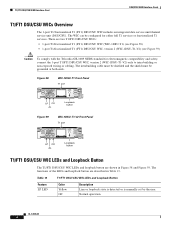
...-through RJ-48S-to-RJ-48S cable to the RJ-48S port on , which indicates that the router is communicating with the DSU/CSU at the 56/64-kbps service provider's central office. T1/FT1 ... • T1/FT1 DSU/CSU WIC LEDs and Loopback Button • Enabling Wetting Current on power to the router. Connect one end of the cable to the 56/64-kbps services wall jack, as shown in Figure 57....-kbps DSU/CSU WIC to a 56/64-kbps Services Wall Jack Switched 56/64-kbps port (RJ-48S) SEE MANUAL BEFORE INSTALLATION DSU 56K Straight-through RJ-48S-to-RJ-48S cable (not included) to connect a 56/64-kbps...
...-through RJ-48S-to-RJ-48S cable to the RJ-48S port on , which indicates that the router is communicating with the DSU/CSU at the 56/64-kbps service provider's central office. T1/FT1 ... • T1/FT1 DSU/CSU WIC LEDs and Loopback Button • Enabling Wetting Current on power to the router. Connect one end of the cable to the 56/64-kbps services wall jack, as shown in Figure 57....-kbps DSU/CSU WIC to a 56/64-kbps Services Wall Jack Switched 56/64-kbps port (RJ-48S) SEE MANUAL BEFORE INSTALLATION DSU 56K Straight-through RJ-48S-to-RJ-48S cable (not included) to connect a 56/64-kbps...
Hardware Installation Guide
Page 92
... 13 Feature LP LED T1/FT1 DSU/CSU WIC LEDs and Loopback Button Color Yellow Off Description Line or loopback state is detected or is manually set by the user. Normal operation. OL-12845-01 4 Figure 58 WIC-1DSU-T1 Front Panel T1 port 41215 SEE... LOOP BACK T1 DSU/CSU DSU CSU T1 LP CD AL Loopback button Figure 59 WIC-1DSU-T1-V2 Front Panel T1 port 88109 SEE MANUAL BEFORE INSTALLATION LP AL CD T1 DSU/CSU LOOP BACK WIC 1DSU-T1 V2 LP CD AL Loopback button T1/FT1 DSU/CSU WIC LEDs...
... 13 Feature LP LED T1/FT1 DSU/CSU WIC LEDs and Loopback Button Color Yellow Off Description Line or loopback state is detected or is manually set by the user. Normal operation. OL-12845-01 4 Figure 58 WIC-1DSU-T1 Front Panel T1 port 41215 SEE... LOOP BACK T1 DSU/CSU DSU CSU T1 LP CD AL Loopback button Figure 59 WIC-1DSU-T1-V2 Front Panel T1 port 88109 SEE MANUAL BEFORE INSTALLATION LP AL CD T1 DSU/CSU LOOP BACK WIC 1DSU-T1 V2 LP CD AL Loopback button T1/FT1 DSU/CSU WIC LEDs...
Hardware Installation Guide
Page 95
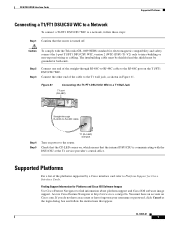
... WIC to a T1 Wall Jack T1 port (RJ-48C) SEE MANUAL BEFORE INSTALLATION LP AL CD LOOP BACK T1 DSU/CSU DSU CSU T1 Straight-through RJ-48C-to-RJ-48C cable to the RJ-48C port on Cisco.com. Access Cisco Feature Navigator at both ends. Caution To comply with the DSU... username or password, click Cancel at the T1 service provider's central office. Check that the CD LED comes on power to the router. You must be grounded at http://www.cisco.com/go/fn. DSU/CSU WAN Interface Cards Supported Platforms Connecting a T1/FT1 DSU/CSU WIC to a Network To connect a T1...
... WIC to a T1 Wall Jack T1 port (RJ-48C) SEE MANUAL BEFORE INSTALLATION LP AL CD LOOP BACK T1 DSU/CSU DSU CSU T1 Straight-through RJ-48C-to-RJ-48C cable to the RJ-48C port on Cisco.com. Access Cisco Feature Navigator at both ends. Caution To comply with the DSU... username or password, click Cancel at the T1 service provider's central office. Check that the CD LED comes on power to the router. You must be grounded at http://www.cisco.com/go/fn. DSU/CSU WAN Interface Cards Supported Platforms Connecting a T1/FT1 DSU/CSU WIC to a Network To connect a T1...
Hardware Installation Guide
Page 98
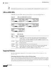
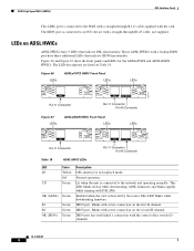
... Platforms For a list of the platforms supported by the router. Figure 62 ADSL and G.SHDSL WIC Front Panels ADASDLSL SEE MANUAL BEFORE INSTALLATION CD LP OK WIC 1ADSL SHDSL SEE MANUAL BEFORE INSTALLATION CD LP OK WIC 1SHDSL ADSL SEE MANUAL BEFORE INSTALLATION WIC 1ADSL IDG CD LP OK ADSL SEE...refers to power status as defined in loopback mode. Yellow when the T1E1 framer detects an alarm. Finding Support Information for Cisco Interface Cards. LEDs on Cisco.com. Enabled when the card is connected to the WIC-1SHDSL-V2 or WIC-1SHDSL-V3 interface cards. You must ...
... Platforms For a list of the platforms supported by the router. Figure 62 ADSL and G.SHDSL WIC Front Panels ADASDLSL SEE MANUAL BEFORE INSTALLATION CD LP OK WIC 1ADSL SHDSL SEE MANUAL BEFORE INSTALLATION CD LP OK WIC 1SHDSL ADSL SEE MANUAL BEFORE INSTALLATION WIC 1ADSL IDG CD LP OK ADSL SEE...refers to power status as defined in loopback mode. Yellow when the T1E1 framer detects an alarm. Finding Support Information for Cisco Interface Cards. LEDs on Cisco.com. Enabled when the card is connected to the WIC-1SHDSL-V2 or WIC-1SHDSL-V3 interface cards. You must ...
Hardware Installation Guide
Page 99
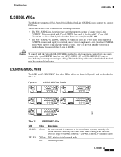
.... Figure 63 G.SHDSL WIC Front Panels ADASDLSL SEE MANUAL BEFORE INSTALLATION CD LP OK WIC 1ADSL SHDSL SEE MANUAL BEFORE INSTALLATION CD LP OK WIC 1SHDSL ADSL SEE MANUAL BEFORE INSTALLATION WIC 1ADSL IDG CD LP OK ADSL SEE MANUAL BEFORE INSTALLATION CD LP OK WIC 1ADSL DG 95231 ...WIC 1SHDSL V2 SHDSL SEE MANUAL BEFORE INSTALLATION LINK LP OK Table 15 G.SHDSL WIC LEDs LED CD LED LP LED Color Green Yellow Off Description Lit when the unit is compatible with Cisco G.SHDSL line cards in the Cisco 6015, Cisco 6130, Cisco 6160, or Cisco 6260 digital subscriber line access ...
.... Figure 63 G.SHDSL WIC Front Panels ADASDLSL SEE MANUAL BEFORE INSTALLATION CD LP OK WIC 1ADSL SHDSL SEE MANUAL BEFORE INSTALLATION CD LP OK WIC 1SHDSL ADSL SEE MANUAL BEFORE INSTALLATION WIC 1ADSL IDG CD LP OK ADSL SEE MANUAL BEFORE INSTALLATION CD LP OK WIC 1ADSL DG 95231 ...WIC 1SHDSL V2 SHDSL SEE MANUAL BEFORE INSTALLATION LINK LP OK Table 15 G.SHDSL WIC LEDs LED CD LED LP LED Color Green Yellow Off Description Lit when the unit is compatible with Cisco G.SHDSL line cards in the Cisco 6015, Cisco 6130, Cisco 6160, or Cisco 6260 digital subscriber line access ...
Hardware Installation Guide
Page 102
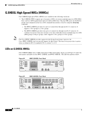
...of DSL: two inverse multiplexing over ATM (IMA) groups or M-pair groups, and it supports 1-Pair groups or 2-Pair groups. Note The Cisco HWIC-2SHDSL provides support for the HWIC-2SHDSL and HWIC-4SHDSL. LEDs on G.SHDSL HWICs The G.SHDSL HWICs have 4 LEDs that indicate DSL ... (SAR) lines. however, the Cisco HWIC-4SHDSL does not provide support for this feature. Figure 64 HWIC-2SHDSL Front Panel HWIC 2SHDSL SHDSL SEE MANUAL BEFORE INSTALLATION EN L0 L1 155562 Figure 65 HWIC-4SHDSL Front Panel HWIC 4SHDSL EN SHDSL SEE MANUAL BEFORE INSTALLATION RJ45 CONNECTOR ONLY L0 ...
...of DSL: two inverse multiplexing over ATM (IMA) groups or M-pair groups, and it supports 1-Pair groups or 2-Pair groups. Note The Cisco HWIC-2SHDSL provides support for the HWIC-2SHDSL and HWIC-4SHDSL. LEDs on G.SHDSL HWICs The G.SHDSL HWICs have 4 LEDs that indicate DSL ... (SAR) lines. however, the Cisco HWIC-4SHDSL does not provide support for this feature. Figure 64 HWIC-2SHDSL Front Panel HWIC 2SHDSL SHDSL SEE MANUAL BEFORE INSTALLATION EN L0 L1 155562 Figure 65 HWIC-4SHDSL Front Panel HWIC 4SHDSL EN SHDSL SEE MANUAL BEFORE INSTALLATION RJ45 CONNECTOR ONLY L0 ...
Hardware Installation Guide
Page 104
... ADSLoISDN HWICs. Figure 66 LEDs ADSLoPOTS HWIC Front Panel LEDs LEDs 127117 LP CD OK ADSL RJ-11 Connector SEE MANUAL BEFORE INSTALLATION LP B1 CD B2 SEE MANUAL OK OK BEFORE INSTALLATION ADSL ISDN BRI S/T RJ-11 Connector RJ-45 Connector Figure 67 LEDs ADSLoISDN HWIC Front Panel... is connected to an NT1 device with a straight-through RJ-11 cable supplied with the card. Lit when the unit is detected by the router. Blinks with active connection on the second B channel. This LED blinks slowly while downloading ADSL firmware, and blinks rapidly while training with DSLAMs....
... ADSLoISDN HWICs. Figure 66 LEDs ADSLoPOTS HWIC Front Panel LEDs LEDs 127117 LP CD OK ADSL RJ-11 Connector SEE MANUAL BEFORE INSTALLATION LP B1 CD B2 SEE MANUAL OK OK BEFORE INSTALLATION ADSL ISDN BRI S/T RJ-11 Connector RJ-45 Connector Figure 67 LEDs ADSLoISDN HWIC Front Panel... is connected to an NT1 device with a straight-through RJ-11 cable supplied with the card. Lit when the unit is detected by the router. Blinks with active connection on the second B channel. This LED blinks slowly while downloading ADSL firmware, and blinks rapidly while training with DSLAMs....
Hardware Installation Guide
Page 107
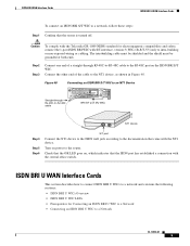
Enter the no shutdown state. Figure 68 Connecting an ADSL Card to the Wall Jack ADSL port (RJ-11) ADSL SEE MANUAL BEFORE INSTALLATION CD LP OK RJ-11 twisted-pair cable 37701 RJ-11 wall jack Alternately, when connecting a G.SHDSL card to a 4-wire patch panel, use a Y-... connect the card to the network, you must configure the DSL interface card in the router configuration. Figure 69 Connecting a G.SHDSL Card to a Patch Panel With a Y-Cable SHDSL port (RJ-11) WIC 1SHDSL V2 SHDSL SEE MANUAL BEFORE INSTALLATION CD LP OK Patch panel RJ-11 twisted-pair cables 10 11 12...
Enter the no shutdown state. Figure 68 Connecting an ADSL Card to the Wall Jack ADSL port (RJ-11) ADSL SEE MANUAL BEFORE INSTALLATION CD LP OK RJ-11 twisted-pair cable 37701 RJ-11 wall jack Alternately, when connecting a G.SHDSL card to a 4-wire patch panel, use a Y-... connect the card to the network, you must configure the DSL interface card in the router configuration. Figure 69 Connecting a G.SHDSL Card to a Patch Panel With a Y-Cable SHDSL port (RJ-11) WIC 1SHDSL V2 SHDSL SEE MANUAL BEFORE INSTALLATION CD LP OK Patch panel RJ-11 twisted-pair cables 10 11 12...
Hardware Installation Guide
Page 108
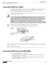
...to the OSP or its wiring. The intra-building port(s) of a straight-through RJ-45-to-RJ-45 cable to the online document Cisco Modular Access Router Cable Specifications for electromagnetic compatibility and safety, connect the HWIC-ADSL-B/ST or HWIC-ADSLI-B/ST ISDN BRI S/T port only to an ISDN ...11 straight-through cable to establish connection between the HWIC and a network device. • Cisco HWIC-4SHDSL-Use a standard RJ-45 straight-through RJ-45-to-RJ-45 cable LP CD B1 OK B2 SEE MANUAL OK BEFORE ADSL ISDN BRI S/T INSTALLATION BRI S/T port (RJ-45) 127428 NT1 device Step...
...to the OSP or its wiring. The intra-building port(s) of a straight-through RJ-45-to-RJ-45 cable to the online document Cisco Modular Access Router Cable Specifications for electromagnetic compatibility and safety, connect the HWIC-ADSL-B/ST or HWIC-ADSLI-B/ST ISDN BRI S/T port only to an ISDN ...11 straight-through cable to establish connection between the HWIC and a network device. • Cisco HWIC-4SHDSL-Use a standard RJ-45 straight-through RJ-45-to-RJ-45 cable LP CD B1 OK B2 SEE MANUAL OK BEFORE ADSL ISDN BRI S/T INSTALLATION BRI S/T port (RJ-45) 127428 NT1 device Step...

