
Hardware Installation Guide
Page 20
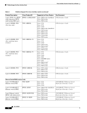
... power 9-port 10/100BASE-T Ethernet switch HWIC HWIC-4ESW-POE HWIC-D-9ESW Supported on Cisco Routers Cisco 1800 series (modular) Cisco 2800 series Cisco 3800 series Cisco 1721 Cisco 1751 Cisco 1760 Cisco 1800 series (modular) Cisco 2600 series Cisco 2800 series Cisco 3600 series Cisco 3700 series Cisco 3800 series Cisco 1721 Cisco 1751 Cisco 1760 Cisco 2600 series Cisco 2800 series2 Cisco 3700 series Cisco 3800 series Cisco 1721 Cisco 1751 Cisco 1760 Cisco...
... power 9-port 10/100BASE-T Ethernet switch HWIC HWIC-4ESW-POE HWIC-D-9ESW Supported on Cisco Routers Cisco 1800 series (modular) Cisco 2800 series Cisco 3800 series Cisco 1721 Cisco 1751 Cisco 1760 Cisco 1800 series (modular) Cisco 2600 series Cisco 2800 series Cisco 3600 series Cisco 3700 series Cisco 3800 series Cisco 1721 Cisco 1751 Cisco 1760 Cisco 2600 series Cisco 2800 series2 Cisco 3700 series Cisco 3800 series Cisco 1721 Cisco 1751 Cisco 1760 Cisco...
Hardware Installation Guide
Page 21
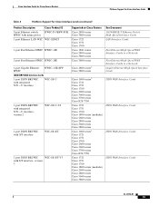
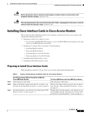
Cisco Interface Cards for Cisco Access Routers Platform Support for Cisco Interface Cards Table 4 Platform Support for Cisco Interface Cards (continued) Product Description Cisco Product ID 9-port Ethernet switch HWIC-D-9ESW-POE HWIC with inline power 1-port Ethernet LAN WIC WIC-1ENET 1-port Fast Ethernet HWIC HWIC-1FE 2-port Fast Ethernet HWIC HWIC-2FE 1-port Gigabit Ethernet HWIC...
Cisco Interface Cards for Cisco Access Routers Platform Support for Cisco Interface Cards Table 4 Platform Support for Cisco Interface Cards (continued) Product Description Cisco Product ID 9-port Ethernet switch HWIC-D-9ESW-POE HWIC with inline power 1-port Ethernet LAN WIC WIC-1ENET 1-port Fast Ethernet HWIC HWIC-1FE 2-port Fast Ethernet HWIC HWIC-2FE 1-port Gigabit Ethernet HWIC...
Hardware Installation Guide
Page 34
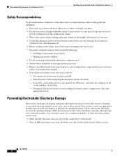
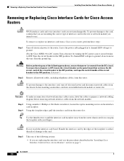
... action. Otherwise, determine the condition of the victim and then call for Cisco Interface Cards Installing Cisco Interface Cards in Cisco Access Routers Safety Recommendations To prevent hazardous conditions, follow these safety recommendations while working with your eyes. • Locate the emergency power-off switch in the room before doing the following electrostatic discharge damage...
... action. Otherwise, determine the condition of the victim and then call for Cisco Interface Cards Installing Cisco Interface Cards in Cisco Access Routers Safety Recommendations To prevent hazardous conditions, follow these safety recommendations while working with your eyes. • Locate the emergency power-off switch in the room before doing the following electrostatic discharge damage...
Hardware Installation Guide
Page 35
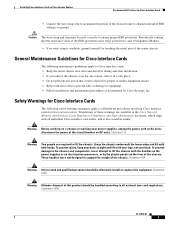
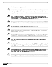
... national laws and regulations. Statement 1030 Warning Ultimate disposal of the chassis. Installing Cisco Interface Cards in Cisco Access Routers Recommended Practices for Cisco Interface Cards • Connect the wrist strap clip to an unpainted portion of the router chassis. disconnect the power at the circuit breaker on DC units. Statement 1040 OL-12842-01 3 These...
... national laws and regulations. Statement 1030 Warning Ultimate disposal of the chassis. Installing Cisco Interface Cards in Cisco Access Routers Recommended Practices for Cisco Interface Cards • Connect the wrist strap clip to an unpainted portion of the router chassis. disconnect the power at the circuit breaker on DC units. Statement 1040 OL-12842-01 3 These...
Hardware Installation Guide
Page 36
... activity. To avoid electric shock, use RJ-45 connectors. Recommended Practices for Cisco Interface Cards Installing Cisco Interface Cards in Cisco Access Routers The following warnings apply in a hazardous situation. For systems with a power switch, line voltages are present within the power supply when the power cord is connected to telephone-network voltage (TNV) circuits. Metal objects...
... activity. To avoid electric shock, use RJ-45 connectors. Recommended Practices for Cisco Interface Cards Installing Cisco Interface Cards in Cisco Access Routers The following warnings apply in a hazardous situation. For systems with a power switch, line voltages are present within the power supply when the power cord is connected to telephone-network voltage (TNV) circuits. Metal objects...
Hardware Installation Guide
Page 37
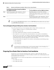
... card. (See the "Installing Single-Wide Interface Cards" section on Cisco access routers, and contains the following tasks: Table 5 Interface Card Hardware Installation Tasks for Cisco Access Routers Step 1 Step 2 Step 3 For All Cisco Access Routers Except Cisco 2800 and Cisco 3800 Series Routers Turn off power to the router. Removing Interface Card Slot Dividers • Installing Single-Wide Interface Cards...
... card. (See the "Installing Single-Wide Interface Cards" section on Cisco access routers, and contains the following tasks: Table 5 Interface Card Hardware Installation Tasks for Cisco Access Routers Step 1 Step 2 Step 3 For All Cisco Access Routers Except Cisco 2800 and Cisco 3800 Series Routers Turn off power to the router. Removing Interface Card Slot Dividers • Installing Single-Wide Interface Cards...
Hardware Installation Guide
Page 38
... power) Tape to secure DC circuit breaker handle • (For certain Cisco access routers) Voice network module for voice interface card installation On some Cisco access routers, voice interface cards must be installed in voice network modules before being installed in the router. Preparing Cisco Router Slots for Cisco Access Routers Step 4 For All Cisco Access Routers Except Cisco 2800 and Cisco 3800 Series Routers...
... power) Tape to secure DC circuit breaker handle • (For certain Cisco access routers) Voice network module for voice interface card installation On some Cisco access routers, voice interface cards must be installed in voice network modules before being installed in the router. Preparing Cisco Router Slots for Cisco Access Routers Step 4 For All Cisco Access Routers Except Cisco 2800 and Cisco 3800 Series Routers...
Hardware Installation Guide
Page 47
... plugged in to channel ESD voltages to ground. (For the Cisco MWR 1941-DC router) Turn off electrical power and disconnect network cables from the DC circuit. Step 3 Remove blank faceplates installed over the slot you are not interchangeable. Step 4 Step 5 (For certain Cisco routers) Prepare the slot for the interface card form factor you...
... plugged in to channel ESD voltages to ground. (For the Cisco MWR 1941-DC router) Turn off electrical power and disconnect network cables from the DC circuit. Step 3 Remove blank faceplates installed over the slot you are not interchangeable. Step 4 Step 5 (For certain Cisco routers) Prepare the slot for the interface card form factor you...
Hardware Installation Guide
Page 48
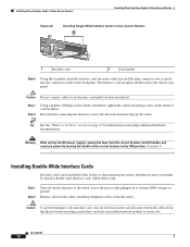
... card faceplate. OL-12842-01 16 The interface card faceplate should contact the chassis rear panel. Leave the power cable plugged in Cisco Access Routers 2 121080 1 Interface card 2 Card guides Step 6 Using the faceplate, push the interface card into place... interface card, follow these steps: Step 1 Step 2 Turn off electrical power and disconnect network cables from the router. Installing Cisco Interface Cards in Cisco Access Routers Installing Cisco Interface Cards in Cisco Access Routers Figure 25 1 Installing Single-Wide Interface Cards in to channel ESD voltages to...
... card faceplate. OL-12842-01 16 The interface card faceplate should contact the chassis rear panel. Leave the power cable plugged in Cisco Access Routers 2 121080 1 Interface card 2 Card guides Step 6 Using the faceplate, push the interface card into place... interface card, follow these steps: Step 1 Step 2 Turn off electrical power and disconnect network cables from the router. Installing Cisco Interface Cards in Cisco Access Routers Installing Cisco Interface Cards in Cisco Access Routers Figure 25 1 Installing Single-Wide Interface Cards in to channel ESD voltages to...
Hardware Installation Guide
Page 49
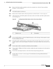
... to Go Next" section on page 27 for future use. Installing Cisco Interface Cards in Cisco Access Routers Installing Cisco Interface Cards in Cisco Access Routers 1 2 121079 1 Interface card 2 Card guides Caution Do not ...touch the interface card board. Step 4 Remove the slot divider. (See the "Removing Interface Card Slot Dividers" section on the interface card faceplate. Caution Do not connect cables to the network and powering...
... to Go Next" section on page 27 for future use. Installing Cisco Interface Cards in Cisco Access Routers Installing Cisco Interface Cards in Cisco Access Routers 1 2 121079 1 Interface card 2 Card guides Caution Do not ...touch the interface card board. Step 4 Remove the slot divider. (See the "Removing Interface Card Slot Dividers" section on the interface card faceplate. Caution Do not connect cables to the network and powering...
Hardware Installation Guide
Page 50
... are supported in to channel ESD voltages to ground. (For the Cisco MWR 1941-DC router) Turn off electrical power to OFF. Leave the power cable plugged in your network module, see the Cisco Network Modules Hardware Installation Guide. Some Cisco network modules have B-channel LEDs that use supports the kind of the circuit breaker in...
... are supported in to channel ESD voltages to ground. (For the Cisco MWR 1941-DC router) Turn off electrical power to OFF. Leave the power cable plugged in your network module, see the Cisco Network Modules Hardware Installation Guide. Some Cisco network modules have B-channel LEDs that use supports the kind of the circuit breaker in...
Hardware Installation Guide
Page 51
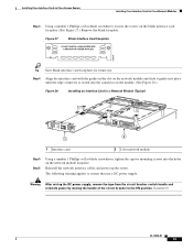
...the ON position. Reinstall the network interface cables and power up the router. Installing Cisco Interface Cards in Cisco Access Routers Installing Cisco Interface Cards in a Network Module (Typical) 2E 2W W1 H7219 B1 B2 BRI S/T 1 ETH 1 ACT LNK ACT LNK WO ETHERNET 0 AUI EN 2 1 Interface card 2 2-slot network module ...interface card faceplates for future use a DC power supply: Warning After wiring the DC power supply, remove the tape from the circuit breaker switch handle and reinstate power by moving the handle of the circuit breaker to routers that use . Step 4 Align the ...
...the ON position. Reinstall the network interface cables and power up the router. Installing Cisco Interface Cards in Cisco Access Routers Installing Cisco Interface Cards in a Network Module (Typical) 2E 2W W1 H7219 B1 B2 BRI S/T 1 ETH 1 ACT LNK ACT LNK WO ETHERNET 0 AUI EN 2 1 Interface card 2 2-slot network module ...interface card faceplates for future use a DC power supply: Warning After wiring the DC power supply, remove the tape from the circuit breaker switch handle and reinstate power by moving the handle of the circuit breaker to routers that use . Step 4 Align the ...
Hardware Installation Guide
Page 52
... the OFF position. Tape the circuit breaker in to channel ESD voltages to ground. (For the Cisco MWR 1941-DC router) Turn off electrical power to pull the interface card faceplate away from the DC circuit. To ensure that services the DC circuit... card from the router. Statement 7 Step 2 Remove all power is removed from the router chassis until you can grip the faceplate with your fingers. Removing or Replacing Cisco Interface Cards for Cisco Access Routers Installing Cisco Interface Cards in Cisco Access Routers Removing or Replacing Cisco Interface Cards for ...
... the OFF position. Tape the circuit breaker in to channel ESD voltages to ground. (For the Cisco MWR 1941-DC router) Turn off electrical power to pull the interface card faceplate away from the DC circuit. To ensure that services the DC circuit... card from the router. Statement 7 Step 2 Remove all power is removed from the router chassis until you can grip the faceplate with your fingers. Removing or Replacing Cisco Interface Cards for Cisco Access Routers Installing Cisco Interface Cards in Cisco Access Routers Removing or Replacing Cisco Interface Cards for ...
Hardware Installation Guide
Page 53
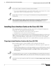
... to provide more information about these cards, see a list of the circuit breaker to the ON position. Installing Cisco Interface Cards in Cisco Access Routers Installing Cisco Interface Cards on the Cisco ICS 7750 Caution Do not connect cables to an interface card until you have installed it. • If you...Where to Go Next" section on page 27 for information on the MRP or ASI 81 card, or the Cisco ICS 7750 will require additional digital signal processors (DSPs). For more processing power. The MRP has two interface card slots (slot 0, slot 1) and the ASI 81 has one interface ...
... to provide more information about these cards, see a list of the circuit breaker to the ON position. Installing Cisco Interface Cards in Cisco Access Routers Installing Cisco Interface Cards on the Cisco ICS 7750 Caution Do not connect cables to an interface card until you have installed it. • If you...Where to Go Next" section on page 27 for information on the MRP or ASI 81 card, or the Cisco ICS 7750 will require additional digital signal processors (DSPs). For more processing power. The MRP has two interface card slots (slot 0, slot 1) and the ASI 81 has one interface ...
Hardware Installation Guide
Page 54
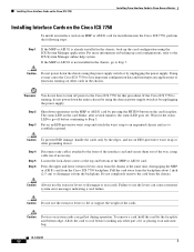
...and secure them out of it or placing it from the chassis. Do not completely remove the card from the backplane. Caution Do not power down operations on the MRP or ASI 81 card by pressing the SHTDN button on other part of the way, using the ICS System ...cards in the chassis. Caution Do not use the levers can get hot during operation. Installing Cisco Interface Cards on the Cisco ICS 7750 Installing Cisco Interface Cards in Cisco Access Routers Installing Interface Cards on the Cisco ICS 7750 To install an interface card on an MRP or ASI 81 card for installation into...
...and secure them out of it or placing it from the chassis. Do not completely remove the card from the backplane. Caution Do not power down operations on the MRP or ASI 81 card by pressing the SHTDN button on other part of the way, using the ICS System ...cards in the chassis. Caution Do not use the levers can get hot during operation. Installing Cisco Interface Cards on the Cisco ICS 7750 Installing Cisco Interface Cards in Cisco Access Routers Installing Interface Cards on the Cisco ICS 7750 To install an interface card on an MRP or ASI 81 card for installation into...
Hardware Installation Guide
Page 56
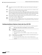
... 7750 Description Shows the status of the MRP or ASI 81: • Blinks green while the card is booting up. • Green after the power-on self-test (POST) is complete, and the card is steady green, and then verify that the interface card installation. This step firmly seats the ... inward at the same time until the LED is operating correctly. Wait until they lock into the chassis. Installing Cisco Interface Cards on the Cisco ICS 7750 Installing Cisco Interface Cards in Cisco Access Routers Tip If an interface card slot on the ASI 81 or MRP is installed in the slot, or that you...
... 7750 Description Shows the status of the MRP or ASI 81: • Blinks green while the card is booting up. • Green after the power-on self-test (POST) is complete, and the card is steady green, and then verify that the interface card installation. This step firmly seats the ... inward at the same time until the LED is operating correctly. Wait until they lock into the chassis. Installing Cisco Interface Cards on the Cisco ICS 7750 Installing Cisco Interface Cards in Cisco Access Routers Tip If an interface card slot on the ASI 81 or MRP is installed in the slot, or that you...
Hardware Installation Guide
Page 65
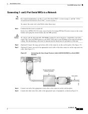
... on page 2, and the "2-Port Asynchronous/Synchronous Serial WIC" section on the surge protector cable. (See Figure 35.) Figure 35 Connecting the Cisco Surge Protector Cable (CAB-SS-SURGE) to a Serial WAN Interface SERIAL 1 CONN SERIAL 0 WIC CONN 2T SEE MANUAL BEFORE INSTALLATION Surge protection...limitations, see the "1- and 2-Port Serial WICs to the WAN, follow these steps: Step 1 Confirm that the router is turned off power by turning OFF the DC power source at both ends. Caution To comply with the Telcordia GR-1089 NEBS standard for electromagnetic compatibility and safety, ...
... on page 2, and the "2-Port Asynchronous/Synchronous Serial WIC" section on the surge protector cable. (See Figure 35.) Figure 35 Connecting the Cisco Surge Protector Cable (CAB-SS-SURGE) to a Serial WAN Interface SERIAL 1 CONN SERIAL 0 WIC CONN 2T SEE MANUAL BEFORE INSTALLATION Surge protection...limitations, see the "1- and 2-Port Serial WICs to the WAN, follow these steps: Step 1 Confirm that the router is turned off power by turning OFF the DC power source at both ends. Caution To comply with the Telcordia GR-1089 NEBS standard for electromagnetic compatibility and safety, ...
Hardware Installation Guide
Page 66
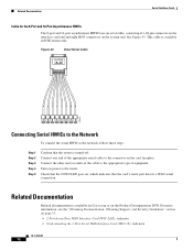
... page 9 • Prerequisites for Connecting Serial HWICs to the Network, page 9 • Connecting Serial HWICs to a network. Protocols supported are five Cisco serial high speed WICs (HWICs). This section describes the HWICs and tells how to connect them to the Network, page 12 4-Port Multiprotocol High Speed...35, X.21, or EIA-530 connector Turn on , which indicates that the CONN LED goes on power to the router by turning ON the DC power source at the circuit breaker. On the Cisco MWR 1941-DC router, turn on power to the router by pressing the power switch to the ON ( | ) position.
... page 9 • Prerequisites for Connecting Serial HWICs to the Network, page 9 • Connecting Serial HWICs to a network. Protocols supported are five Cisco serial high speed WICs (HWICs). This section describes the HWICs and tells how to connect them to the Network, page 12 4-Port Multiprotocol High Speed...35, X.21, or EIA-530 connector Turn on , which indicates that the CONN LED goes on power to the router by turning ON the DC power source at the circuit breaker. On the Cisco MWR 1941-DC router, turn on power to the router by pressing the power switch to the ON ( | ) position.
Hardware Installation Guide
Page 72
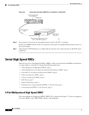
...For more information, see the "Obtaining Documentation, Obtaining Support, and Security Guidelines" section on , which indicates that the router is available in DTE format only. Connect the other end (or ends) of the cable to the network, follow ...Turn on the card faceplate. Connect one end of the appropriate serial cable to the connector on power to the router. Figure 43 Octal Serial Cable 127422 Connecting Serial HWICs to the Network To connect the serial HWIC ...Product Documentation DVD. Related Documentation Related documentation is available on Cisco.com or on the system end.
...For more information, see the "Obtaining Documentation, Obtaining Support, and Security Guidelines" section on , which indicates that the router is available in DTE format only. Connect the other end (or ends) of the cable to the network, follow ...Turn on the card faceplate. Connect one end of the appropriate serial cable to the connector on power to the router. Figure 43 Octal Serial Cable 127422 Connecting Serial HWICs to the Network To connect the serial HWIC ...Product Documentation DVD. Related Documentation Related documentation is available on Cisco.com or on the system end.
Hardware Installation Guide
Page 78
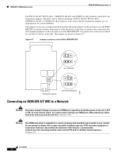
... in Figure 47. When detaching cables, detach the end away from the unit first. The jumpers are factory-configured in WAN ports regardless of whether power to -point connection or as a source of a passive-bus connection. Set the termination jumpers to the A position to a Network H8586 Warning Hazardous network voltages are...
... in Figure 47. When detaching cables, detach the end away from the unit first. The jumpers are factory-configured in WAN ports regardless of whether power to -point connection or as a source of a passive-bus connection. Set the termination jumpers to the A position to a Network H8586 Warning Hazardous network voltages are...


