User Guide
Page 4
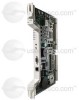
...TCC-I will take about 15 to 20 minutes. TCC-I Timing Communication and Control Card Description Install TCC-I faceplate has eight LEDs. All TCC-I uses a 10Base-T LAN port for the presence or absence of FMECs unless the TCC-I card. Note Cisco does not support operating the ONS 15454 SDH with the active TCC... LEDs are network-level indicators. Replace the unit if the FAIL LED persists. The ACT/STBY (Active/Standby) LED indicates the TCC-I is less than 50 ms. The TCC-I protection switches conform to the port accessible on the active TCC-I, the newly inserted TCC-I will copy...
...TCC-I will take about 15 to 20 minutes. TCC-I Timing Communication and Control Card Description Install TCC-I faceplate has eight LEDs. All TCC-I uses a 10Base-T LAN port for the presence or absence of FMECs unless the TCC-I card. Note Cisco does not support operating the ONS 15454 SDH with the active TCC... LEDs are network-level indicators. Replace the unit if the FAIL LED persists. The ACT/STBY (Active/Standby) LED indicates the TCC-I is less than 50 ms. The TCC-I protection switches conform to the port accessible on the active TCC-I, the newly inserted TCC-I will copy...
User Guide
Page 7
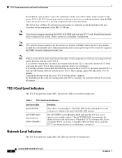
...the shelf, it up will take about 15 to 20 minutes. Replace the unit if the faulty state persists. If its software version does not match the version on the active TCC-I, the newly inserted TCC-I card has been installed in the correct slot (Slot 7 or slot ...15454 SDH TCC-I card takes several minutes to reboot and display the amber standby LED after rebooting. If one or more of the Cisco Transport Controller (CTC) software screen conditions according to "Verify Successful Turn Up of the TCC-I Card" section on page 7 are installing or removing the TCC-I Card Step 1 Verify that the card...
...the shelf, it up will take about 15 to 20 minutes. Replace the unit if the faulty state persists. If its software version does not match the version on the active TCC-I, the newly inserted TCC-I card has been installed in the correct slot (Slot 7 or slot ...15454 SDH TCC-I card takes several minutes to reboot and display the amber standby LED after rebooting. If one or more of the Cisco Transport Controller (CTC) software screen conditions according to "Verify Successful Turn Up of the TCC-I Card" section on page 7 are installing or removing the TCC-I Card Step 1 Verify that the card...

Operation Guide
Page 39
... the main power connector and/or 2) while the housing is intended for installing the Cisco ONS 15454. Incorrectly connecting this equipment to install, replace, or service this equipment. Warning This equipment must be installed and maintained by service ...) • Coaxial and DS-1 cable installation • Card installation • Fiber-optic cable installation • Cable routing and management • Ferrite installation • Hardware specifications • Hardware and software compatibility Note The Cisco ONS 15454 assembly is open. Hardware Installation CH A P T E...
... the main power connector and/or 2) while the housing is intended for installing the Cisco ONS 15454. Incorrectly connecting this equipment to install, replace, or service this equipment. Warning This equipment must be installed and maintained by service ...) • Coaxial and DS-1 cable installation • Card installation • Fiber-optic cable installation • Cable routing and management • Ferrite installation • Hardware specifications • Hardware and software compatibility Note The Cisco ONS 15454 assembly is open. Hardware Installation CH A P T E...

Operation Guide
Page 47
... to the rack, install the remaining mounting screws. When the shelf assembly is that you can replace the filter without removing the fan tray. Align the screw holes on the ONS 15454 to install the fan-tray air filter, you can install four shelf assemblies in a rack.... 3 Step 4 Step 5 Ensure that can be aggregated in a single node), you can link the nodes November 2001 Cisco ONS 15454 Installation and Operations Guide 1-9 The advantage to using their OC-N cards (i.e., create a fiber-optic bus) to the fan intake. Note Use at least one inch between the third-party shelf...
... to the rack, install the remaining mounting screws. When the shelf assembly is that you can replace the filter without removing the fan tray. Align the screw holes on the ONS 15454 to install the fan-tray air filter, you can install four shelf assemblies in a rack.... 3 Step 4 Step 5 Ensure that can be aggregated in a single node), you can link the nodes November 2001 Cisco ONS 15454 Installation and Operations Guide 1-9 The advantage to using their OC-N cards (i.e., create a fiber-optic bus) to the fan intake. Note Use at least one inch between the third-party shelf...
Operation Guide
Page 55
... or both sides of the shelf assembly, the ONS 15454 hosts up to 48 circuits. For EIA replacement procedures, refer to provide coaxial cable connections. You can screw down the cover and the board using DS-1, DS-3, DS3XM-6, or EC-1 cards. November 2001 Cisco ONS 15454 Installation and Operations Guide 1-17 EIAs are attached to...
... or both sides of the shelf assembly, the ONS 15454 hosts up to 48 circuits. For EIA replacement procedures, refer to provide coaxial cable connections. You can screw down the cover and the board using DS-1, DS-3, DS3XM-6, or EC-1 cards. November 2001 Cisco ONS 15454 Installation and Operations Guide 1-17 EIAs are attached to...

Operation Guide
Page 60
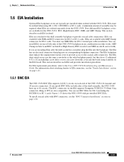
...(P/N 48-0358) at 8-10 lbs to secure the cover panel to the card and backplane. Replace the lower backplane cover, and insert and tighten the five screws to the ONS 15454 and pull it . Remove the EIA card from the shelf assembly. Figure 1-18 shows an SMB EIA installation. Figure ...1-16 Installing the BNC EIA 43764 1-22 Cisco ONS 15454 Installation and Operations Guide ...
...(P/N 48-0358) at 8-10 lbs to secure the cover panel to the card and backplane. Replace the lower backplane cover, and insert and tighten the five screws to the ONS 15454 and pull it . Remove the EIA card from the shelf assembly. Figure 1-18 shows an SMB EIA installation. Figure ...1-16 Installing the BNC EIA 43764 1-22 Cisco ONS 15454 Installation and Operations Guide ...

Operation Guide
Page 63
...However, do not install the ONS 15454 Release 3.1 XC10G, OC-192, and OC-48 any slot (AS) cards. Fan speed is controlled by the TCC+ sensors is displayed on the LCD screen. After you install the fan tray, you should only need to replace or clean the fan-tray air filter... high. The front door can only be left in place when removing or installing the fan tray but removal is recommended. November 2001 Cisco ONS 15454 Installation and Operations Guide 1-25 Chapter 1 Hardware Installation Fan-Tray Assembly Installation 1.7 Fan-Tray Assembly Installation The fan-tray assembly is located...
...However, do not install the ONS 15454 Release 3.1 XC10G, OC-192, and OC-48 any slot (AS) cards. Fan speed is controlled by the TCC+ sensors is displayed on the LCD screen. After you install the fan tray, you should only need to replace or clean the fan-tray air filter... high. The front door can only be left in place when removing or installing the fan tray but removal is recommended. November 2001 Cisco ONS 15454 Installation and Operations Guide 1-25 Chapter 1 Hardware Installation Fan-Tray Assembly Installation 1.7 Fan-Tray Assembly Installation The fan-tray assembly is located...

Operation Guide
Page 195
... that will connect to the new node through its west port (Node 1 in the Figure 5-15 example). Install the OC-N cards in the ONS 15454 that you created in Step 1, remove the fiber connections from the node that will connect to the new node. Log into the... Step 10 Log into CTC and display the BLSR nodes in network view. Click the Maintenance > Ring tabs. b. b. Caution Traffic is Node 1/Slot 5. Replace the removed fibers with fibers that are connected to ensure the cards are active. November 2001 Cisco ONS 15454 Installation and Operations Guide 5-19 In a BLSR, these facility ...
... that will connect to the new node through its west port (Node 1 in the Figure 5-15 example). Install the OC-N cards in the ONS 15454 that you created in Step 1, remove the fiber connections from the node that will connect to the new node. Log into the... Step 10 Log into CTC and display the BLSR nodes in network view. Click the Maintenance > Ring tabs. b. b. Caution Traffic is Node 1/Slot 5. Replace the removed fibers with fibers that are connected to ensure the cards are active. November 2001 Cisco ONS 15454 Installation and Operations Guide 5-19 In a BLSR, these facility ...

Operation Guide
Page 283
... DS1N-14 card and a protection group with DS1N-14 cards. c. The ONS 15454 must say Protect/Standby (shown in Slots 1 through 6 and/or Slots 12 through 17. Make sure the slot you will be replaced with DS1-14 cards. Under Selected Group, click the protect card. If they...must run CTC Release 2.0 or later. Next to Switch Commands, select Clear. Troubleshoot the working card and slot to determine why the card cannot carry working card: a. November 2001 Cisco ONS 15454 Installation and Operations Guide 7-31 Click the protection group that contains Slot 3 or Slot 15 (where...
... DS1N-14 card and a protection group with DS1N-14 cards. c. The ONS 15454 must say Protect/Standby (shown in Slots 1 through 6 and/or Slots 12 through 17. Make sure the slot you will be replaced with DS1-14 cards. Under Selected Group, click the protect card. If they...must run CTC Release 2.0 or later. Next to Switch Commands, select Clear. Troubleshoot the working card and slot to determine why the card cannot carry working card: a. November 2001 Cisco ONS 15454 Installation and Operations Guide 7-31 Click the protection group that contains Slot 3 or Slot 15 (where...

Operation Guide
Page 285
... next level of the DS3-12 cards you will move the cards to determine why the card cannot carry working traffic. Click the Provisioning > Protection tabs. November 2001 Cisco ONS 15454 Installation and Operations Guide 7-33 Under Available Cards, highlight the cards that the new card appears as shown in Slots 1 ...15 (where you are the protection slots, will be replaced with DS3N-12 cards. b. If they fail to change to convert. Troubleshoot the working slot should change , do not continue. Verify that you want in the Protect Card field. Click OK. Repeat Steps 2 and 3 ...
... next level of the DS3-12 cards you will move the cards to determine why the card cannot carry working traffic. Click the Provisioning > Protection tabs. November 2001 Cisco ONS 15454 Installation and Operations Guide 7-33 Under Available Cards, highlight the cards that the new card appears as shown in Slots 1 ...15 (where you are the protection slots, will be replaced with DS3N-12 cards. b. If they fail to change to convert. Troubleshoot the working slot should change , do not continue. Verify that you want in the Protect Card field. Click OK. Repeat Steps 2 and 3 ...

Operation Guide
Page 290
.... An incomplete or incorrect count can be caused by changing node timing settings, changing the time zone settings on CTC, replacing a card, resetting a card, changing port states, or by using the Baseline button. Cisco ONS 15454 Installation and Operations Guide 8-4 November 2001 The value represents the counter for the current time period. View the Prev...
.... An incomplete or incorrect count can be caused by changing node timing settings, changing the time zone settings on CTC, replacing a card, resetting a card, changing port states, or by using the Baseline button. Cisco ONS 15454 Installation and Operations Guide 8-4 November 2001 The value represents the counter for the current time period. View the Prev...

Operation Guide
Page 432
...by equipment for addressing, type-of a card. IP address 32-bit address assigned to link the port with the fiber optic network. Cisco ONS 15454 Installation and Operations Guide D-6 November 2001 HDLC High-Level Data Link Control. Network layer protocol in the SONET line overhead ... to one of a network number, an optional subnetwork number, and a host number. K K bytes Automatic protection switching bytes. H Hard reset The physical removal and insertion of -service specification, fragmentation and reassembly, and security. Hot swap The process of replacing a failed component while...
...by equipment for addressing, type-of a card. IP address 32-bit address assigned to link the port with the fiber optic network. Cisco ONS 15454 Installation and Operations Guide D-6 November 2001 HDLC High-Level Data Link Control. Network layer protocol in the SONET line overhead ... to one of a network number, an optional subnetwork number, and a host number. K K bytes Automatic protection switching bytes. H Hard reset The physical removal and insertion of -service specification, fragmentation and reassembly, and security. Hot swap The process of replacing a failed component while...