
User Guide
Page 1
..., installation procedures, removal instructions, and technical specifications. Use this document in conjunction with the Cisco ONS 15454 SDH Installation and Operations Guide and the Cisco ONS 15454 SDH Troubleshooting and Reference Guide when working with TCC-I cards. Cisco Systems, Inc. Corporate Headquarters: Cisco Systems, Inc., 170 West Tasman Drive, San Jose, CA 95134-1706 USA Copyright © 2002...
..., installation procedures, removal instructions, and technical specifications. Use this document in conjunction with the Cisco ONS 15454 SDH Installation and Operations Guide and the Cisco ONS 15454 SDH Troubleshooting and Reference Guide when working with TCC-I cards. Cisco Systems, Inc. Corporate Headquarters: Cisco Systems, Inc., 170 West Tasman Drive, San Jose, CA 95134-1706 USA Copyright © 2002...

User Guide
Page 2
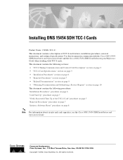
... MIN REM SYNC ACO ACO ASYNC LAN 61207 Installing ONS 15454 SDH TCC-I faceplate and Figure 2 shows a block diagram of the card. TCC-I Timing Communication and Control Card Description TCC-I Timing Communication and Control Card Description The TCC-I also ensures that the system maintains Stratum 3 E (G.813) timing requirements. The TCC-I performs system initialization, provisioning, alarm reporting, maintenance, diagnostics, IP...
... MIN REM SYNC ACO ACO ASYNC LAN 61207 Installing ONS 15454 SDH TCC-I faceplate and Figure 2 shows a block diagram of the card. TCC-I Timing Communication and Control Card Description TCC-I Timing Communication and Control Card Description The TCC-I also ensures that the system maintains Stratum 3 E (G.813) timing requirements. The TCC-I performs system initialization, provisioning, alarm reporting, maintenance, diagnostics, IP...

User Guide
Page 3
...Installing ONS 15454 SDH TCC-I selects a recovered clock, a BITS or an internal Stratum 3 E reference as primary or secondary timing sources. The TCC-I Cards 3 You can be routed over the module. Peer-to ten DCCs can provision any two cards in ...DCC. TCC-I Timing Communication and Control Card Description Figure 2 TCC-I block diagram RAM Flash DCC Processor 10BaseT Modem Timing Controller RAM Flash Framer/ LIU Control Processor Message Router TDM Crossconnect TDM/SCC Mux Ethernet Hub B a 10BaseT c k Craft p l a n e 61208 TCC-I Functionality The TCC-I ...
...Installing ONS 15454 SDH TCC-I selects a recovered clock, a BITS or an internal Stratum 3 E reference as primary or secondary timing sources. The TCC-I Cards 3 You can be routed over the module. Peer-to ten DCCs can provision any two cards in ...DCC. TCC-I Timing Communication and Control Card Description Figure 2 TCC-I block diagram RAM Flash DCC Processor 10BaseT Modem Timing Controller RAM Flash Framer/ LIU Control Processor Message Router TDM Crossconnect TDM/SCC Mux Ethernet Hub B a 10BaseT c k Craft p l a n e 61208 TCC-I Functionality The TCC-I ...
User Guide
Page 4
... protection switching standards when the BER counts are network-level indicators. The ACT/STBY (Active/Standby) LED indicates the TCC-I is lit during Reset. Note When a second TCC-I card is less than 50 ms. The TCC-I uses a 10Base-T LAN port for user ...TCC-I, the newly inserted TCC-I will take about 40 minutes. TCC-I Timing Communication and Control Card Description Install TCC-I cards in Slots 7 and 11 for the presence or absence of FMECs unless the TCC-I(s) card has reached the active/standby state. Note Cisco does not support operating the ONS 15454 SDH with the active TCC...
... protection switching standards when the BER counts are network-level indicators. The ACT/STBY (Active/Standby) LED indicates the TCC-I is lit during Reset. Note When a second TCC-I card is less than 50 ms. The TCC-I uses a 10Base-T LAN port for user ...TCC-I, the newly inserted TCC-I will take about 40 minutes. TCC-I Timing Communication and Control Card Description Install TCC-I cards in Slots 7 and 11 for the presence or absence of FMECs unless the TCC-I(s) card has reached the active/standby state. Note Cisco does not support operating the ONS 15454 SDH with the active TCC...

User Guide
Page 5
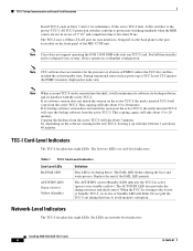
Table 2 TCC-I System-Level Indicators System-Level LEDs Red CRIT LED Red MAJ LED Yellow MIN LED Red REM LED Green SYNC LED Green ACO LED Definition Used to indicate major alarms in the network at the local terminal. Provides first-level alarm ...to indicate that node timing is present in the network at the local terminal. Stratum 3 E, per ITU-T G.813 - Access: on the backplane. After pressing the alarm cutoff (ACO) button, the green ACO LED illuminates. TCC-I Timing Communication and Control Card Description . TCC-I Card Specifications • CTC Software - Holdover Stability:...
Table 2 TCC-I System-Level Indicators System-Level LEDs Red CRIT LED Red MAJ LED Yellow MIN LED Red REM LED Green SYNC LED Green ACO LED Definition Used to indicate major alarms in the network at the local terminal. Provides first-level alarm ...to indicate that node timing is present in the network at the local terminal. Stratum 3 E, per ITU-T G.813 - Access: on the backplane. After pressing the alarm cutoff (ACO) button, the green ACO LED illuminates. TCC-I Timing Communication and Control Card Description . TCC-I Card Specifications • CTC Software - Holdover Stability:...

User Guide
Page 6
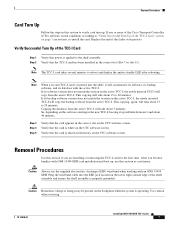
... is operating. Figure 3 Installing cards in an ONS 15454 SDH 61239 FAN FAIL CRIT MAJ MIN Ejector Guide rail Installing ONS 15454 SDH TCC-I card has to be present on the back plane by closing the ejectors. Step 1 Step 2 Step 3 Open the card ejectors. Caution Always use the supplied... electrostatic discharge (ESD) wristband when working with ONS 15454 SDH card installation and boot up, use...
... is operating. Figure 3 Installing cards in an ONS 15454 SDH 61239 FAN FAIL CRIT MAJ MIN Ejector Guide rail Installing ONS 15454 SDH TCC-I card has to be present on the back plane by closing the ejectors. Step 1 Step 2 Step 3 Open the card ejectors. Caution Always use the supplied... electrostatic discharge (ESD) wristband when working with ONS 15454 SDH card installation and boot up, use...
User Guide
Page 7
... the system is properly grounded. Use caution when servicing. 78-14610-01 Installing ONS 15454 SDH TCC-I . Verify Successful Turn Up of the Cisco Transport Controller (CTC) software screen conditions according to reboot and display the amber standby LED... after rebooting. If its software version does not match the version on the active TCC-I, the newly inserted TCC-I card has been installed in the correct slot (Slot 7 or slot 11). If its database with an ONS 15454...
... the system is properly grounded. Use caution when servicing. 78-14610-01 Installing ONS 15454 SDH TCC-I . Verify Successful Turn Up of the Cisco Transport Controller (CTC) software screen conditions according to reboot and display the amber standby LED... after rebooting. If its software version does not match the version on the active TCC-I, the newly inserted TCC-I card has been installed in the correct slot (Slot 7 or slot 11). If its database with an ONS 15454...

User Guide
Page 8
...the "Lost connection to node, changing to perform a card pull on an active TCC-I card, initiate a software reset on the active TCC-I card first. (See the "Initiate a Software Reset" section on the TCC-I Cards 8 78-14610-01 Figure 4 Resetting from the ...shelf. Removal Procedures Note To determine whether the TCC-I card is in active mode or standby mode, view it in the CTC software and position the cursor over the TCC-I card pull-down menu. Installing ONS 15454 SDH TCC-I card. Step 1 Step 2 Step 3 If you need to Network...
...the "Lost connection to node, changing to perform a card pull on an active TCC-I card, initiate a software reset on the active TCC-I card first. (See the "Initiate a Software Reset" section on the TCC-I Cards 8 78-14610-01 Figure 4 Resetting from the ...shelf. Removal Procedures Note To determine whether the TCC-I card is in active mode or standby mode, view it in the CTC software and position the cursor over the TCC-I card pull-down menu. Installing ONS 15454 SDH TCC-I card. Step 1 Step 2 Step 3 If you need to Network...

User Guide
Page 9
Related Documentation Related Documentation • DOC-7813038= Cisco ONS 15454 SDH Installation and Operations Guide • DOC-7813037= Cisco ONS 15454 SDH Troubleshooting and Reference Guide 78-14610-01 Installing ONS 15454 SDH TCC-I Cards 9
Related Documentation Related Documentation • DOC-7813038= Cisco ONS 15454 SDH Installation and Operations Guide • DOC-7813037= Cisco ONS 15454 SDH Troubleshooting and Reference Guide 78-14610-01 Installing ONS 15454 SDH TCC-I Cards 9

User Guide
Page 10
..., iQuick Study, LightStream, Linksys, MeetingPlace, MGX, Networkers, Networking Academy, Network Registrar, PIX, ProConnect, ScriptShare, SMARTnet, StackWise, The Fastest Way to the Human Network are registered trademarks of Cisco Systems, Inc.; CCVP, the Cisco logo, and Welcome to Increase Your Internet Quotient, and... service and Cisco currently supports RSS version 2.0. The use of the word partner does not imply a partnership relationship between Cisco and any other countries. This document is a service mark of their respective owners. Installing ONS 15454 SDH TCC-I Cards 10 78-...
..., iQuick Study, LightStream, Linksys, MeetingPlace, MGX, Networkers, Networking Academy, Network Registrar, PIX, ProConnect, ScriptShare, SMARTnet, StackWise, The Fastest Way to the Human Network are registered trademarks of Cisco Systems, Inc.; CCVP, the Cisco logo, and Welcome to Increase Your Internet Quotient, and... service and Cisco currently supports RSS version 2.0. The use of the word partner does not imply a partnership relationship between Cisco and any other countries. This document is a service mark of their respective owners. Installing ONS 15454 SDH TCC-I Cards 10 78-...

Operation Guide
Page 5
...Cables on the AMP Champ EIA 1-43 1.12 Card Installation 1-44 1.12.1 Slot Requirements 1-45 Procedure: Install the TCC+ and XC/XCVT/XC10G Cards 1-47 Procedure: Install Optical, Electrical, and Ethernet Cards 1-48 Procedure: Install the AIC Card 1-49 1.12.2 Gigabit Interface Converter 1-50 Procedure... 1-61 Procedure: Attach Ferrites to Wire-Wrap Pin Fields 1-63 1.16 ONS 15454 Assembly Specifications 1-64 1.16.1 Bandwidth 1-64 1.16.2 Slot Assignments 1-64 1.16.3 Cards 1-64 1.16.4 Configurations 1-65 1.16.5 Cisco Transport Controller 1-65 1.16.6 External LAN Interface 1-65 1.16.7 TL1 Craft Interface...
...Cables on the AMP Champ EIA 1-43 1.12 Card Installation 1-44 1.12.1 Slot Requirements 1-45 Procedure: Install the TCC+ and XC/XCVT/XC10G Cards 1-47 Procedure: Install Optical, Electrical, and Ethernet Cards 1-48 Procedure: Install the AIC Card 1-49 1.12.2 Gigabit Interface Converter 1-50 Procedure... 1-61 Procedure: Attach Ferrites to Wire-Wrap Pin Fields 1-63 1.16 ONS 15454 Assembly Specifications 1-64 1.16.1 Bandwidth 1-64 1.16.2 Slot Assignments 1-64 1.16.3 Cards 1-64 1.16.4 Configurations 1-65 1.16.5 Cisco Transport Controller 1-65 1.16.6 External LAN Interface 1-65 1.16.7 TL1 Craft Interface...

Operation Guide
Page 6
... Port on CTC 2-13 2.6 Working with the CTC Window 2-13 2.6.1 Node View 2-14 2.6.1.1 CTC Card Colors 2-14 2.6.1.2 Node View Card Shortcuts 2-15 2.6.1.3 Node View Tabs 2-15 2.6.2 Network View 2-15 2.6.2.1 CTC Node Colors 2-16 2.6.2.2 Network View Tasks 2-16 2.6.2.3 Creating Domains 2-17 2.6.2.4 Changing the Network View Background Color 2-19 Cisco ONS 15454 Installation and Operations Guide vi November 2001
... Port on CTC 2-13 2.6 Working with the CTC Window 2-13 2.6.1 Node View 2-14 2.6.1.1 CTC Card Colors 2-14 2.6.1.2 Node View Card Shortcuts 2-15 2.6.1.3 Node View Tabs 2-15 2.6.2 Network View 2-15 2.6.2.1 CTC Node Colors 2-16 2.6.2.2 Network View Tasks 2-16 2.6.2.3 Creating Domains 2-17 2.6.2.4 Changing the Network View Background Color 2-19 Cisco ONS 15454 Installation and Operations Guide vi November 2001

Operation Guide
Page 7
...R November 2001 Procedure: Modify the Network or Domain Background Color 2-19 2.6.2.5 Changing the Network View Background Image 2-19 Procedure: Change the Network View Background Image 2-20 Procedure: Add a Node to the Current Session 2-21 2.6.3 Card View 2-21 2.7 CTC Navigation 2-...15454 Timing 3-12 3.6.1 Network Timing Example 3-13 3.6.2 Synchronization Status Messaging 3-14 Procedure: Set up ONS 15454 Timing 3-14 Procedure: Set Up Internal Timing 3-17 3.7 Viewing ONS 15454 Inventory 3-18 3.8 Viewing CTC Software Versions 3-19 IP Networking 4-1 4.1 IP Networking Overview 4-1 Cisco ONS 15454...
...R November 2001 Procedure: Modify the Network or Domain Background Color 2-19 2.6.2.5 Changing the Network View Background Image 2-19 Procedure: Change the Network View Background Image 2-20 Procedure: Add a Node to the Current Session 2-21 2.6.3 Card View 2-21 2.7 CTC Navigation 2-...15454 Timing 3-12 3.6.1 Network Timing Example 3-13 3.6.2 Synchronization Status Messaging 3-14 Procedure: Set up ONS 15454 Timing 3-14 Procedure: Set Up Internal Timing 3-17 3.7 Viewing ONS 15454 Inventory 3-18 3.8 Viewing CTC Software Versions 3-19 IP Networking 4-1 4.1 IP Networking Overview 4-1 Cisco ONS 15454...

Operation Guide
Page 8
...Static Route 4-8 4.2.6 Scenario 6: Static Route for Multiple CTCs 4-9 4.2.7 Scenario 7: Using OSPF 4-10 Procedure: Set up OSPF 4-12 4.3 Viewing the ONS 15454 Routing Table 4-15 SONET Topologies 5-1 5.1 Before You Begin 5-1 5.2 Bidirectional Line Switched Rings 5-1 5.2.1 Two-Fiber BLSRs 5-2 5.2.2 Four-Fiber BLSRs 5-4 5.2.3 ...Procedure: Install the UPSR Trunk Cards 5-30 Procedure: Configure the UPSR DCC Terminations 5-31 Procedure: Enable the UPSR Ports 5-32 5.3.3 Adding and Removing UPSR Nodes 5-32 Procedure: Switch UPSR Traffic 5-32 Cisco ONS 15454 Installation and Operations Guide viii ...
...Static Route 4-8 4.2.6 Scenario 6: Static Route for Multiple CTCs 4-9 4.2.7 Scenario 7: Using OSPF 4-10 Procedure: Set up OSPF 4-12 4.3 Viewing the ONS 15454 Routing Table 4-15 SONET Topologies 5-1 5.1 Before You Begin 5-1 5.2 Bidirectional Line Switched Rings 5-1 5.2.1 Two-Fiber BLSRs 5-2 5.2.2 Four-Fiber BLSRs 5-4 5.2.3 ...Procedure: Install the UPSR Trunk Cards 5-30 Procedure: Configure the UPSR DCC Terminations 5-31 Procedure: Enable the UPSR Ports 5-32 5.3.3 Adding and Removing UPSR Nodes 5-32 Procedure: Switch UPSR Traffic 5-32 Cisco ONS 15454 Installation and Operations Guide viii ...

Operation Guide
Page 9
... a Linear ADM to UPSR 5-42 Procedure: Convert a Linear ADM to a BLSR 5-47 5.6 Path-Protected Mesh Networks 5-50 Circuits and Tunnels 6-1 6.1 Circuits Overview 6-1 6.2 Creating Circuits and VT Tunnels 6-2 Procedure: Create an Automatically...Card Capacities 6-15 6.8.1 VT1.5 Cross-Connects 6-16 6.8.2 VT Tunnels 6-19 6.9 Creating DCC Tunnels 6-21 Procedure: Provision a DCC Tunnel 6-22 Card Provisioning 7-1 7.1 Performance Monitoring Thresholds 7-1 7.2 Provisioning Electrical Cards 7-2 7.2.1 DS-1 Card Parameters 7-3 Procedure: Modify Line and Threshold Settings for the DS-1 Card 7-3 Cisco ONS 15454...
... a Linear ADM to UPSR 5-42 Procedure: Convert a Linear ADM to a BLSR 5-47 5.6 Path-Protected Mesh Networks 5-50 Circuits and Tunnels 6-1 6.1 Circuits Overview 6-1 6.2 Creating Circuits and VT Tunnels 6-2 Procedure: Create an Automatically...Card Capacities 6-15 6.8.1 VT1.5 Cross-Connects 6-16 6.8.2 VT Tunnels 6-19 6.9 Creating DCC Tunnels 6-21 Procedure: Provision a DCC Tunnel 6-22 Card Provisioning 7-1 7.1 Performance Monitoring Thresholds 7-1 7.2 Provisioning Electrical Cards 7-2 7.2.1 DS-1 Card Parameters 7-3 Procedure: Modify Line and Threshold Settings for the DS-1 Card 7-3 Cisco ONS 15454...

Operation Guide
Page 10
...Orderwire 7-29 Procedure: Provision AIC Orderwire 7-29 7.5.3 Using the AIC Orderwire 7-30 7.6 Converting DS-1 and DS-3 Cards From 1:1 to 1:N Protection 7-30 Procedure: Convert DS1-14 Cards From 1:1 to 1:N Protection 7-31 Procedure: Convert DS3-12 Cards From 1:1 to 1:N Protection 7-33 Performance Monitoring 8-1 8.1 Using the Performance Monitoring Screen 8-1 8.1.1 Viewing PMs 8-2...the Performance Monitoring Screen 8-5 8.1.4 Using the Signal-Type Menu 8-6 Procedure: Select Signal-Type Menus on the Performance Monitoring Screen 8-6 Cisco ONS 15454 Installation and Operations Guide x November 2001
...Orderwire 7-29 Procedure: Provision AIC Orderwire 7-29 7.5.3 Using the AIC Orderwire 7-30 7.6 Converting DS-1 and DS-3 Cards From 1:1 to 1:N Protection 7-30 Procedure: Convert DS1-14 Cards From 1:1 to 1:N Protection 7-31 Procedure: Convert DS3-12 Cards From 1:1 to 1:N Protection 7-33 Performance Monitoring 8-1 8.1 Using the Performance Monitoring Screen 8-1 8.1.1 Viewing PMs 8-2...the Performance Monitoring Screen 8-5 8.1.4 Using the Signal-Type Menu 8-6 Procedure: Select Signal-Type Menus on the Performance Monitoring Screen 8-6 Cisco ONS 15454 Installation and Operations Guide x November 2001

Operation Guide
Page 11
... Ring 9-10 9.3.3 Hub and Spoke Ethernet Circuit Provisioning 9-14 Procedure: Provision a Hub and Spoke Ethernet Circuit 9-14 9.3.4 Ethernet Manual Cross-Connects 9-16 Procedure: Provision a Single-card EtherSwitch Manual Cross-Connect 9-17 Procedure: Provision a Multicard EtherSwitch Manual Cross-Connect 9-19 9.4 VLAN Support 9-21 Cisco ONS 15454 Installation and Operations Guide xi
... Ring 9-10 9.3.3 Hub and Spoke Ethernet Circuit Provisioning 9-14 Procedure: Provision a Hub and Spoke Ethernet Circuit 9-14 9.3.4 Ethernet Manual Cross-Connects 9-16 Procedure: Provision a Single-card EtherSwitch Manual Cross-Connect 9-17 Procedure: Provision a Multicard EtherSwitch Manual Cross-Connect 9-19 9.4 VLAN Support 9-21 Cisco ONS 15454 Installation and Operations Guide xi

Operation Guide
Page 13
... D I X November 2001 10.3.1.4 Row Display Options 10-11 10.3.2 Applying Alarm Profiles 10-11 Procedure: Apply an Alarm Profile at the Card View 10-13 Procedure: Apply an Alarm Profile at the Node View 10-13 10.4 Suppressing Alarms 10-14 Procedure: Suppressing Alarms 10-14...Information Bases 11-5 11.5 SNMP Traps 11-6 11.6 SNMP Community Names 11-8 11.7 SNMP Remote Network Monitoring 11-8 11.7.1 Ethernet Statistics Group 11-9 11.7.2 History Control Group 11-9 11.7.3 Ethernet ... DC Power Disconnection Warning B-4 DC Power Connection Warning B-5 Cisco ONS 15454 Installation and Operations Guide xiii
... D I X November 2001 10.3.1.4 Row Display Options 10-11 10.3.2 Applying Alarm Profiles 10-11 Procedure: Apply an Alarm Profile at the Card View 10-13 Procedure: Apply an Alarm Profile at the Node View 10-13 10.4 Suppressing Alarms 10-14 Procedure: Suppressing Alarms 10-14...Information Bases 11-5 11.5 SNMP Traps 11-6 11.6 SNMP Community Names 11-8 11.7 SNMP Remote Network Monitoring 11-8 11.7.1 Ethernet Statistics Group 11-9 11.7.2 History Control Group 11-9 11.7.3 Ethernet ... DC Power Disconnection Warning B-4 DC Power Connection Warning B-5 Cisco ONS 15454 Installation and Operations Guide xiii

Operation Guide
Page 15
...1-28 Figure 1-29 Figure 1-30 Figure 1-31 FIGURES Cisco ONS 15454 dimensions 1-6 Reversing the mounting brackets (23-inch position to 19-inch position) 1-7 Mounting an ONS 15454 in a rack 1-8 A four-shelf node configuration 1-10 A four-shelf ONS 15454 Bay Assembly 1-11 The front-door erasable label 1-12... connectors 1-39 DS-1 electrical interface adapter (balun) 1-40 A backplane with SMB EIA for DS-1 cables 1-41 Installing cards in the ONS 15454 1-45 Installing a GBIC on an E1000-2 card 1-51 Installing fiber-optic cables 1-53 November 2001 Cisco ONS 15454 Installation and Operations Guide xv
...1-28 Figure 1-29 Figure 1-30 Figure 1-31 FIGURES Cisco ONS 15454 dimensions 1-6 Reversing the mounting brackets (23-inch position to 19-inch position) 1-7 Mounting an ONS 15454 in a rack 1-8 A four-shelf node configuration 1-10 A four-shelf ONS 15454 Bay Assembly 1-11 The front-door erasable label 1-12... connectors 1-39 DS-1 electrical interface adapter (balun) 1-40 A backplane with SMB EIA for DS-1 cables 1-41 Installing cards in the ONS 15454 1-45 Installing a GBIC on an E1000-2 card 1-51 Installing fiber-optic cables 1-53 November 2001 Cisco ONS 15454 Installation and Operations Guide xv

Operation Guide
Page 16
... Figure 3-5 Figure 3-6 Attaching a fiber boot 1-54 Managing cables on the front panel 1-55 Routing fiber-optic cables on the optical-card faceplate 1-56 Fold-down front door of the cable-management tray (displaying the cable routing channel) 1-57 Routing coaxial cable through the ... CTC data for export 2-28 Setting up general network information 3-4 Selecting the IP address option 3-5 Changing the IP address 3-5 Selecting the Save Configuration option 3-5 Saving and rebooting the TCC+ 3-5 Creating a 1+1 protection group 3-10 Cisco ONS 15454 Installation and Operations Guide xvi November 2001
... Figure 3-5 Figure 3-6 Attaching a fiber boot 1-54 Managing cables on the front panel 1-55 Routing fiber-optic cables on the optical-card faceplate 1-56 Fold-down front door of the cable-management tray (displaying the cable routing channel) 1-57 Routing coaxial cable through the ... CTC data for export 2-28 Setting up general network information 3-4 Selecting the IP address option 3-5 Changing the IP address 3-5 Selecting the Save Configuration option 3-5 Saving and rebooting the TCC+ 3-5 Creating a 1+1 protection group 3-10 Cisco ONS 15454 Installation and Operations Guide xvi November 2001